differential TOYOTA RAV4 2006 Service Repair Manual
[x] Cancel search | Manufacturer: TOYOTA, Model Year: 2006, Model line: RAV4, Model: TOYOTA RAV4 2006Pages: 2000, PDF Size: 45.84 MB
Page 133 of 2000

CHASSIS - 4WD SYSTEM CH-66
4WD SYSTEM
DESCRIPTION
The 4WD system of the ’06 RAV4 uses an active torque control 4WD system.
It is a compact, lightweight, and high performance 4WD system that optimally controls the torque
distribution to the front and rear wheels through the electric control coupling in the rear differential.
ACTIVE TORQUE CONTROL 4WD SYSTEM
1. General
Based on information provided by various sensors, the 4WD ECU controls the amperage that is applied
to the electric control coupling, in order to transmit drive torque to the rear wheels when needed, and in
the amount needed. The following describes the features of the active torque control 4WD system.
Traction performance
Realizes stable start-off and acceleration performance
Driving stability performanceRealizes stable cornering performance
Fuel economyRealizes better fuel economy by transmitting drive torque to the rear
wheels when needed, in the amount needed.
A four-wheel drive lock switch has been provided. This enables the driver to select between the AUTO
and LOCK modes by operating the switch. The system optimally controls the torque distribution to the
front and rear wheels in the respective modes.
Mode
Four-wheel Drive
Lock Switch and
Indicator Light
Outline
AUTOOFF
Optimally distributes drive torque to the front and rear wheels.
Ensures optimal start-off performance during a start-off, based on
information provided by various sensors.
Suppresses the tight corner braking phenomenon* during low-speed
cornering.
Reduces the amount of torque distribution to the rear wheels and
improves fuel economy when the system judges that the vehicle is
traveling steadily.
Disengages the 4WD during braking deceleration.
LOCKON
Distributes the maximum torque limit to the rear wheels.
Distributes the maximum torque limit to the rear wheels during
start-off.
Distributes optimal torque during low-speed cornering.
Disengages the 4WD during braking deceleration.
Disengages the LOCK mode and transfers to the AUTO mode when
the vehicle speed exceeds 40 km / h (25 mph).
*: Tight corner braking phenomenon: a condition in which the brakes are applied due to a rotational difference
between the front and rear wheels, such as during low-speed cornering in the 4WD mode.
The 4WD ECU effects cooperative control with the skid control ECU, in order to control the drive torque
distribution to the front and rear wheels in accordance with information received from the skid control
ECU. These controls ensure a smooth acceleration and driving stability.
Page 179 of 2000

SERVICE SPECIFICATIONS – U151E AUTOMATIC TRANSMISSIONSS–47
SS
TORQUE SPECIFICATIONS
Automatic Transaxle Assembly
Part Tightened N*m kgf*cm ft*lbf
Park/neutral position switch Nut 6.9 70 61 in.*lbf
Bolt 5.4 55 48 in.*lbf
Control shaft lever x Control shaft 13 133 10
Shift control cable x Control shaft lever 15 153 11
Transaxle housing x Engine block Upper side bolt 64 653 47
Lower side bolt
A37 377 27
Lower side bolt
B46 470 34
Torque converter clutch x Drive plate 41 418 30
Flywheel housing under cover x Automatic transaxle 7.8 80 69 in.*lbf
Front engine mounting bracket x Transaxle 64 653 47
Rear engine mounting bracket x Transaxle 45 459 33
Engine mounting bracket LH x Transaxle 64 653 47
Oil filler tube x Transaxle
Oil filler tube x Front engine mounting bracket5.5 56 49 in.*lbf
Control cable bracket No. 1 x Transaxle 12 122 9
Control cable bracket No. 2 x Transaxle 12 122 9
Oil cooler inlet elbow x Transaxle 27 276 20
Oil cooler outlet elbow x Transaxle 27 276 20
Starter x Transaxle37 377 27
Starter wire x Starter9.8 100 88 in.*lbf
Speed sensor (NC) x Transaxle 11 112 8
Speed sensor (NT) x Transaxle 11 112 8
Drain plug x Oil pan47 479 35
Transmission wire x Transaxle 5.4 55 48 in.*lbf
ATF temperature sensor x Valve body 6.6 67 58 in.*lbf
Oil pan x Transaxle7.8 80 69 in.*lbf
Solenoid valve x Valve body SL2, DSL, S4 11 110 8
SL1, SL3 6.6 67 58 in.*lbf
Valve body x Transaxle11 11 2 8
Oil strainer x Valve body11 11 2 8
Floor shift assembly x Body12 122 9
Control cable clamp x Engine mounting insulator 12 122 9
Differential gear lube apply tube x Transaxle housing 9.8 100 87 in.*lbf
Front planetary gear lock nut 280 3,355 207
Brake apply tube clamp x Transaxle case 5.4 55 48 in.*lbf
Transaxle case No. 1 plug x Transaxle rear cover 7.4 75 65 in.*lbf
Transaxle rear cover x Transaxle case Bolt A 19 194 14
Other bolt 25 255 18
Parking lock pawl shaft x Transaxle case 9.8 100 87 in.*lbf
Oil pump assembly x Transaxle case 22 226 16
Transaxle housing x Transaxle case Bolt A 22 254 16
Bolt B 29 295 21
Bolt C 29 295 21
Bolt D 22 254 16
Automatic transmission case plug x Transaxle housing 7.4 75 65 in.*lbf
Automatic transmission case plug x Transaxle case 7.4 75 65 in.*lbf
Page 180 of 2000
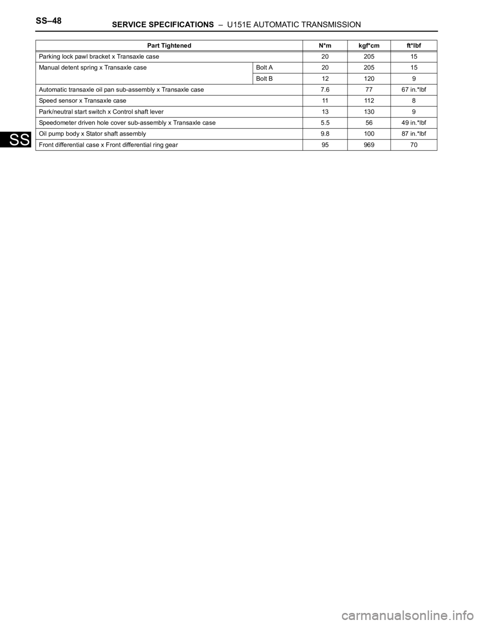
SS–48SERVICE SPECIFICATIONS – U151E AUTOMATIC TRANSMISSION
SS
Parking lock pawl bracket x Transaxle case 20 205 15
Manual detent spring x Transaxle case Bolt A 20 205 15
Bolt B 12 120 9
Automatic transaxle oil pan sub-assembly x Transaxle case 7.6 77 67 in.*lbf
Speed sensor x Transaxle case 11 112 8
Park/neutral start switch x Control shaft lever 13 130 9
Speedometer driven hole cover sub-assembly x Transaxle case 5.5 56 49 in.*lbf
Oil pump body x Stator shaft assembly 9.8 100 87 in.*lbf
Front differential case x Front differential ring gear 95 969 70Part Tightened N*m kgf*cm ft*lbf
Page 181 of 2000

SERVICE SPECIFICATIONS – DIFFERENTIALSS–75
SS
TORQUE SPECIFICATIONS
Differential
Part Tightened N*m kgf*cm ft.*lbf
Rear differential No. 2 support x
Rear suspension member86 877 63
Rear differential support x Rear
suspension member140 1,428 103
Rear differential No. 2 support x
Rear differential
Rear differential No. 1 support x
Rear differential55 561 41
Rear differential support x Rear
differential98 999 72
Drain plug x Differential carrier
Filler plug x Differential carrier39 398 29
Electromagnetic coupling x Stud
bolt8.0 82 71 in.*lbf
Electromagnetic coupling x
Differential carrier19.6 200 14
Yoke x Differential carrier 5.0 51 44 in.*lbf
Drive pinion nut x Differential
drive pinion245 or less 2,498 or less 181 or less
Differential side bearing retainer x
Differential carrier34.3 350 25
Differential carrier x Differential
breather plug oil deflector5.0 51 44 in.*lbf
Differential ring gear x Differential
case90 918 66
Page 221 of 2000

INTRODUCTION – TERMSIN–49
IN
IAT Intake Air Temperature Intake or Inlet Air Temperature
ICM Ignition Control Module -
IFI Indirect Fuel Injection Indirect Injection (IDL)
IFS Inertia Fuel-Shutoff -
ISC Idle Speed Control -
KS Knock Sensor Knock Sensor
MAF Mass Airflow Air Flow Meter
MAP Manifold Absolute Pressure Manifold Pressure Intake Vacuum
MC Mixture ControlElectric Bleed Air Control Valve (EBCV)
Mixture Control Valve (MCV)
Electric Air Control Valve (EACV)
MDP Manifold Differential Pressure -
MFI Multiport Fuel Injection Electronic Fuel Injection (EFI)
MIL Malfunction Indicator Lamp Check Engine Lamp
MST Manifold Surface Temperature -
MVZ Manifold Vacuum Zone -
NVRAM Non-Volatile Random Access Memory -
O2S Oxygen Sensor Oxygen Sensor, O2 Sensor (O2S)
OBD On-Board Diagnostic On-Board Diagnostic System (OBD)
OC Oxidation Catalytic Converter Oxidation Catalyst Converter (OC), CCo
OL Open Loop Open Loop
PAIR Pulsed Secondary Air Injection Air Suction (AS)
PCM Powertrain Control Module -
PNP Park/Neutral Position -
PROM Programmable Read Only Memory -
PSP Power Steering Pressure -
PTOX Periodic Trap OxidizerDiesel Particulate Filter (DPF)
Diesel Particulate Trap (DPT)
RAM Random Access Memory Random Access Memory (RAM)
RM Relay Module -
ROM Read Only Memory Read Only Memory (ROM)
RPM Engine Speed Engine Speed
SC Supercharger Supercharger
SCB Supercharger Bypass E-ABV
SFI Sequential Multiport Fuel Injection Electronic Fuel Injection (EFI), Sequential Injection
SPL Smoke Puff Limiter -
SRI Service Reminder Indicator -
SRT System Readiness Test -
ST Scan Tool -
TB Throttle Body Throttle Body
TBI Throttle Body Fuel InjectionSingle Point Injection
Central Fuel Injection (Ci)
TC Turbocharger Turbocharger
TCC Torque Converter Clutch Torque Converter
TCM Transmission Control Module Transmission ECU, ECT ECU
TP Throttle Position Throttle Position
TR Transmission Range -
TVV Thermal Vacuum ValveBimetallic Vacuum Switching Valve (BVSV)
Thermostatic Vacuum Switching Valve (TVSV) SAE
ABBREVIATIONSSAE TERMS TOYOTA TERMS ( )-ABBREVIATIONS
Page 364 of 2000
AX–288U151F AUTOMATIC TRANSAXLE – DIFFERENTIAL CASE
AX
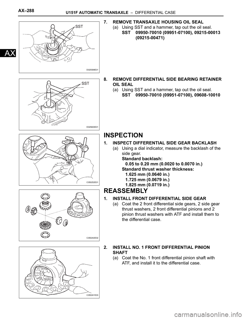
7. REMOVE TRANSAXLE HOUSING OIL SEAL
(a) Using SST and a hammer, tap out the oil seal.
SST 09950-70010 (09951-07100), 09215-00013
(09215-00471)
8. REMOVE DIFFERENTIAL SIDE BEARING RETAINER
OIL SEAL
(a) Using SST and a hammer, tap out the oil seal.
SST 09950-70010 (09951-07100), 09608-10010
INSPECTION
1. INSPECT DIFFERENTIAL SIDE GEAR BACKLASH
(a) Using a dial indicator, measure the backlash of the
side gear.
Standard backlash:
0.05 to 0.20 mm (0.0020 to 0.0070 in.)
Standard thrust washer thickness:
1.625 mm (0.0640 in.)
1.725 mm (0.0679 in.)
1.825 mm (0.0719 in.)
REASSEMBLY
1. INSTALL FRONT DIFFERENTIAL SIDE GEAR
(a) Coat the 2 front differential side gears, 2 side gear
thrust washers, 2 front differential pinions and 2
pinion thrust washers with ATF and install them to
the differential case.
2. INSTALL NO. 1 FRONT DIFFERENTIAL PINION
SHAFT
(a) Coat the No. 1 front differential pinion shaft with
ATF, and install it to the differential case.
D025599E01
D025600E01
C050252E01
C050242E02
C050241E03
Page 365 of 2000
U151F AUTOMATIC TRANSAXLE – DIFFERENTIAL CASEAX–289
AX
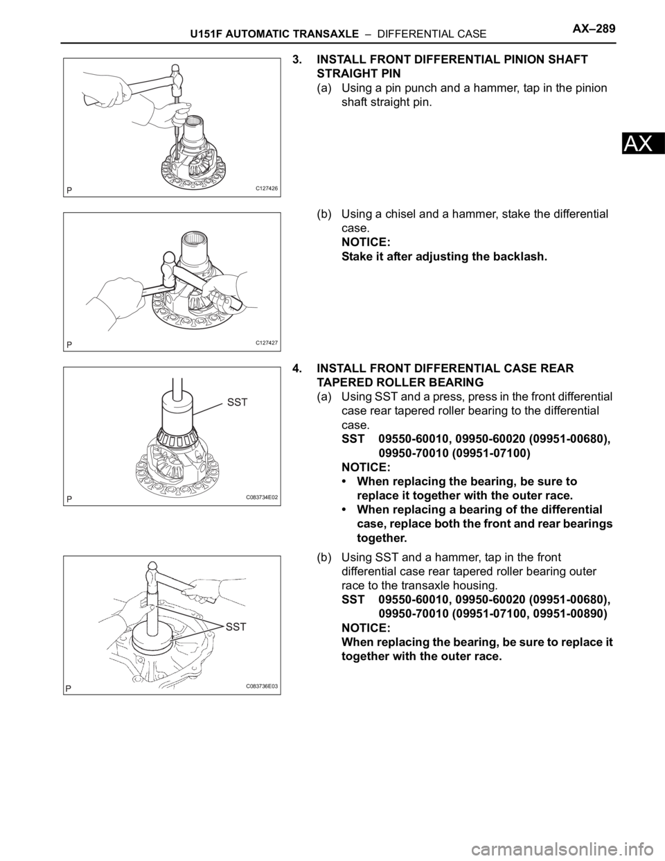
3. INSTALL FRONT DIFFERENTIAL PINION SHAFT
STRAIGHT PIN
(a) Using a pin punch and a hammer, tap in the pinion
shaft straight pin.
(b) Using a chisel and a hammer, stake the differential
case.
NOTICE:
Stake it after adjusting the backlash.
4. INSTALL FRONT DIFFERENTIAL CASE REAR
TAPERED ROLLER BEARING
(a) Using SST and a press, press in the front differential
case rear tapered roller bearing to the differential
case.
SST 09550-60010, 09950-60020 (09951-00680),
09950-70010 (09951-07100)
NOTICE:
• When replacing the bearing, be sure to
replace it together with the outer race.
• When replacing a bearing of the differential
case, replace both the front and rear bearings
together.
(b) Using SST and a hammer, tap in the front
differential case rear tapered roller bearing outer
race to the transaxle housing.
SST 09550-60010, 09950-60020 (09951-00680),
09950-70010 (09951-07100, 09951-00890)
NOTICE:
When replacing the bearing, be sure to replace it
together with the outer race.
C127426
C127427
C083734E02
C083736E03
Page 366 of 2000
AX–290U151F AUTOMATIC TRANSAXLE – DIFFERENTIAL CASE
AX
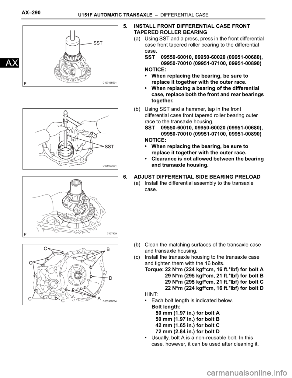
5. INSTALL FRONT DIFFERENTIAL CASE FRONT
TAPERED ROLLER BEARING
(a) U si ng SST and a pres s, pr es s in the f ron t di fferent ial
case front tapered roller bearing to the differential
case.
SST 09550-60010, 09950-60020 (09951-00680),
09950-70010 (09951-07100, 09951-00890)
NOTICE:
• When replacing the bearing, be sure to
replace it together with the outer race.
• When replacing a bearing of the differential
case, replace both the front and rear bearings
together.
(b) Using SST and a hammer, tap in the front
differential case front tapered roller bearing outer
race to the transaxle housing.
SST 09550-60010, 09950-60020 (09951-00680),
09950-70010 (09951-07100, 09951-00890)
NOTICE:
• When replacing the bearing, be sure to
replace it together with the outer race.
• Clearance is not allowed between the bearing
and transaxle housing.
6. ADJUST DIFFERENTIAL SIDE BEARING PRELOAD
(a) Install the differential assembly to the transaxle
case.
(b) Clean the matching surfaces of the transaxle case
and transaxle housing.
(c) Install the transaxle housing to the transaxle case
and tighten them with the 16 bolts.
Torque: 22 N*m (224 kgf*cm, 16 ft.*lbf) for bolt A
29 N*m (295 kgf*cm, 21 ft.*lbf) for bolt B
29 N*m (295 kgf*cm, 21 ft.*lbf) for bolt C
22 N*m (224 kgf*cm, 16 ft.*lbf) for bolt D
HINT:
• Each bolt length is indicated below.
Bolt length:
50 mm (1.97 in.) for bolt A
50 mm (1.97 in.) for bolt B
42 mm (1.65 in.) for bolt C
72 mm (2.84 in.) for bolt D
• Usually, bolt A is a non-reusable bolt. In this
case, however, it can be used after cleaning it.
C127428E01
D025603E01
C127429
D003568E04
Page 367 of 2000
U151F AUTOMATIC TRANSAXLE – DIFFERENTIAL CASEAX–291
AX
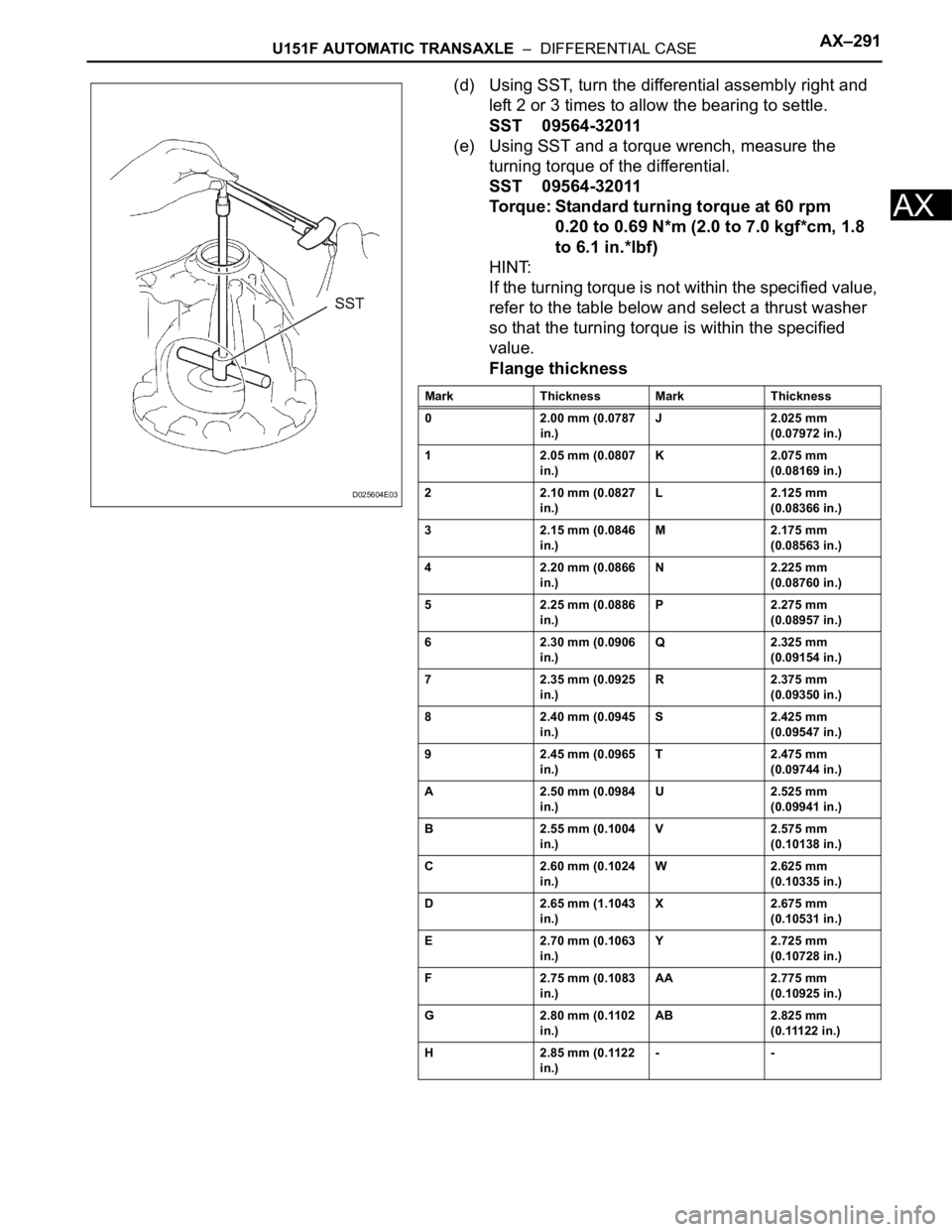
(d) Using SST, turn the differential assembly right and
left 2 or 3 times to allow the bearing to settle.
SST 09564-32011
(e) Using SST and a torque wrench, measure the
turning torque of the differential.
SST 09564-32011
Torque: Standard turning torque at 60 rpm
0.20 to 0.69 N*m (2.0 to 7.0 kgf*cm, 1.8
to 6.1 in.*lbf)
HINT:
If the turning torque is not within the specified value,
refer to the table below and select a thrust washer
so that the turning torque is within the specified
value.
Flange thickness
D025604E03
Mark Thickness Mark Thickness
0 2.00 mm (0.0787
in.)J 2.025 mm
(0.07972 in.)
1 2.05 mm (0.0807
in.)K 2.075 mm
(0.08169 in.)
2 2.10 mm (0.0827
in.)L 2.125 mm
(0.08366 in.)
3 2.15 mm (0.0846
in.)M 2.175 mm
(0.08563 in.)
4 2.20 mm (0.0866
in.)N 2.225 mm
(0.08760 in.)
5 2.25 mm (0.0886
in.)P 2.275 mm
(0.08957 in.)
6 2.30 mm (0.0906
in.)Q 2.325 mm
(0.09154 in.)
7 2.35 mm (0.0925
in.)R 2.375 mm
(0.09350 in.)
8 2.40 mm (0.0945
in.)S 2.425 mm
(0.09547 in.)
9 2.45 mm (0.0965
in.)T 2.475 mm
(0.09744 in.)
A 2.50 mm (0.0984
in.)U 2.525 mm
(0.09941 in.)
B 2.55 mm (0.1004
in.)V 2.575 mm
(0.10138 in.)
C 2.60 mm (0.1024
in.)W 2.625 mm
(0.10335 in.)
D 2.65 mm (1.1043
in.)X 2.675 mm
(0.10531 in.)
E 2.70 mm (0.1063
in.)Y 2.725 mm
(0.10728 in.)
F 2.75 mm (0.1083
in.)AA 2.775 mm
(0.10925 in.)
G 2.80 mm (0.1102
in.)AB 2.825 mm
(0.11122 in.)
H 2.85 mm (0.1122
in.)--
Page 368 of 2000
AX–292U151F AUTOMATIC TRANSAXLE – DIFFERENTIAL CASE
AX
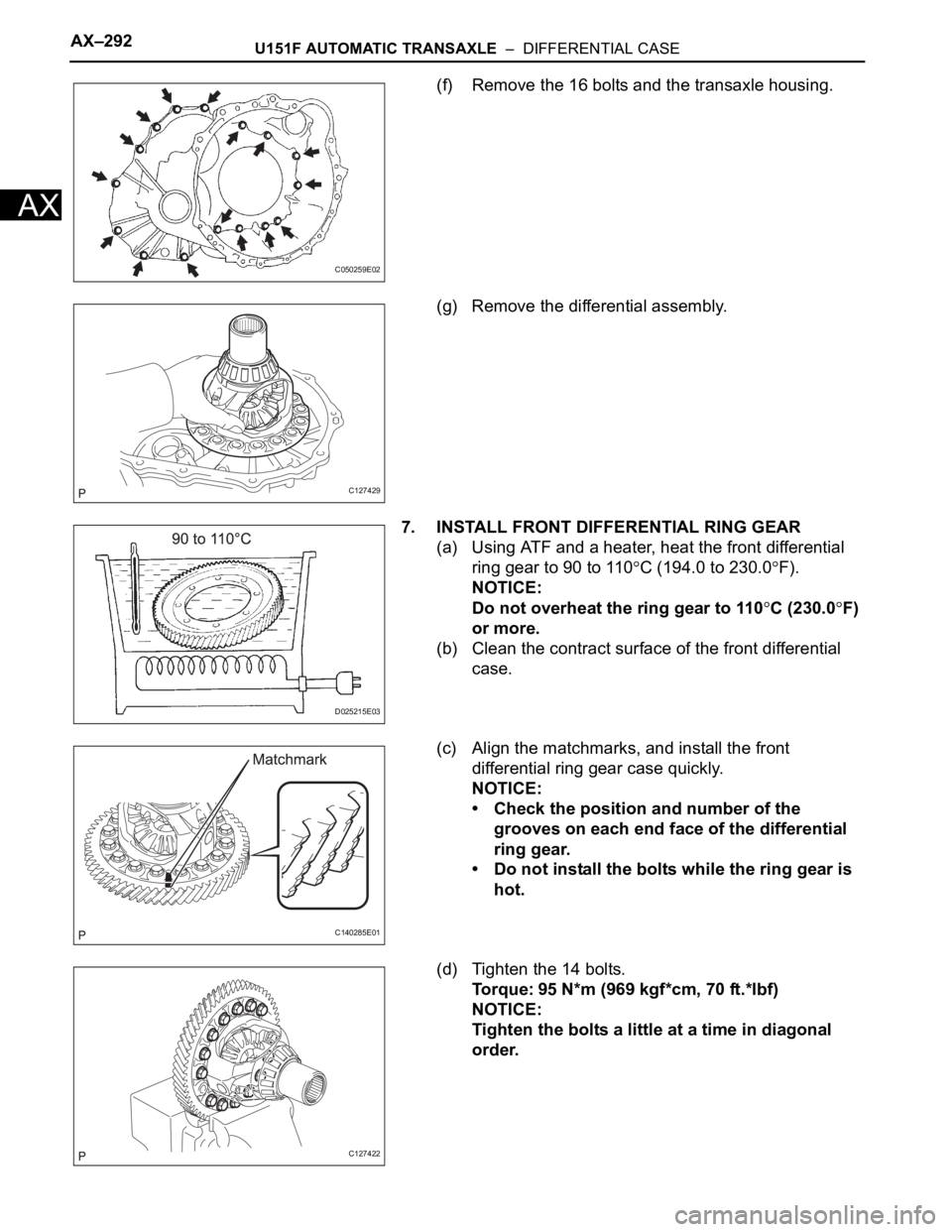
(f) Remove the 16 bolts and the transaxle housing.
(g) Remove the differential assembly.
7. INSTALL FRONT DIFFERENTIAL RING GEAR
(a) Using ATF and a heater, heat the front differential
ring gear to 90 to 110
C (194.0 to 230.0F).
NOTICE:
Do not overheat the ring gear to 110
C (230.0F)
or more.
(b) Clean the contract surface of the front differential
case.
(c) Align the matchmarks, and install the front
differential ring gear case quickly.
NOTICE:
• Check the position and number of the
grooves on each end face of the differential
ring gear.
• Do not install the bolts while the ring gear is
hot.
(d) Tighten the 14 bolts.
Torque: 95 N*m (969 kgf*cm, 70 ft.*lbf)
NOTICE:
Tighten the bolts a little at a time in diagonal
order.
C050259E02
C127429
D025215E03
C140285E01
C127422