check oil TOYOTA RAV4 2006 Service Repair Manual
[x] Cancel search | Manufacturer: TOYOTA, Model Year: 2006, Model line: RAV4, Model: TOYOTA RAV4 2006Pages: 2000, PDF Size: 45.84 MB
Page 12 of 2000

ENGINE - 2AZ-FE ENGINE
01NEG34Y
Oil Jets
Check
Va l v e
Oil
Bottom Side View Oil Jet Cross SectionEG-15
Oil Capacity
Liters (US qts, Imp. qts)
Dry
5.0 (5.3, 4.4)
with Oil Filter4.3 (4.5, 3.8)
without Oil Filter4.1 (3.8, 3.1)
2. Oil Jet
Piston oil jets for cooling and lubricating the pistons are used in the cylinder block.
These oil jets contain a check valve to prevent oil from being fed when the oil pressure is low. This prevents
the overall oil pressure in the engine from dropping.
Page 79 of 2000

ENGINE - 2GR-FE ENGINE
285EG21
Timing Chain Cover
Wa t e r P u m p G a s k e t
Wa t e r P u m pWater Pump Swirl
Chamber
Oil Pump
Housing
Oil Pump RotorsTiming Chain
Cover
Oil Pump Chamber
View from Front Side View from Back Side
285EG22
Oil
Passage
Check Ball
Check Ball
Spring
Plunger SpringPlunger
Roller Rocker ArmCam
Oil
Passage
Hydraulic
Lash Adjuster
Service Tip
Valve clearance adjustment is not necessary because a hydraulic lash adjuster is used in this model.
EG-83
4. Timing Chain Cover
The timing chain cover has an integrated construction consisting of the cooling system (water pump and
water passage) and the lubrication system (oil pump and oil passage). Thus, the number of parts has been
reduced to reduce weight.
5. Hydraulic Lash Adjuster
The hydraulic lash adjuster, which is located at the fulcrum of the roller rocker arm, consists primarily of
a plunger, plunger spring, check ball, and check ball spring.
The engine oil that is supplied by the cylinder head and the built-in spring actuates the hydraulic lash
adjuster. The oil pressure and the spring force that act on the plunger push the roller rocker arm against
the cam, in order to adjust the valve clearance that is created during the opening and closing of the valve.
As a result, engine noise is reduced.
Page 82 of 2000
ENGINE - 2GR-FE ENGINE
285EG24
Timing Chain Cover
Oil Pump
Housing
Oil Pump Rotors
(Cycloid Rotor)Crankshaft
To Cylinder
Block
From Oil
Filter
To
Oil FilterFrom
Oil Strainer
Oil passage in the oil pump
285EG25
Oil Jet Cross Section
Oil JetsCheck
Va l v eEngine Oil EG-86
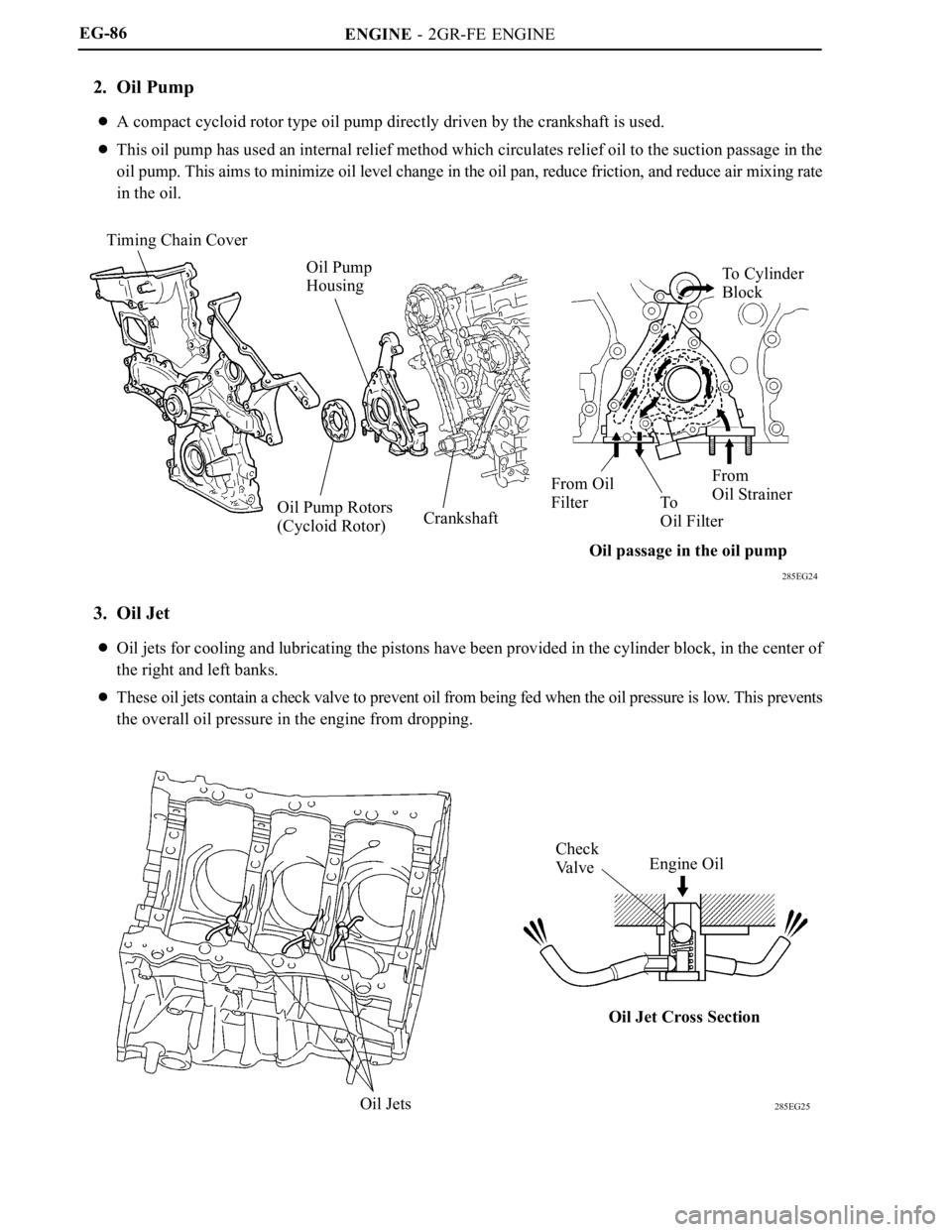
2. Oil Pump
A compact cycloid rotor type oil pump directly driven by the crankshaft is used.
This oil pump has used an internal relief method which circulates relief oil to the suction passage in the
oil pump. This aims to minimize oil level change in the oil pan, reduce friction, and reduce air mixing rate
in the oil.
3. Oil Jet
Oil jets for cooling and lubricating the pistons have been provided in the cylinder block, in the center of
the right and left banks.
These oil jets contain a check valve to prevent oil from being fed when the oil pressure is low. This prevents
the overall oil pressure in the engine from dropping.
Page 182 of 2000

MAINTENANCE – UNDER HOODMA–7
MA
GENERAL MAINTENANCE
(2006/01- )
1. GENERAL NOTES
• Maintenance requirements vary depending on the
country.
• Check the maintenance schedule in the owner's
manual supplement.
• Following the maintenance schedule is mandatory.
• Determine the appropriate time to service the vehicle
using either miles driven or time elapsed, whichever
reaches the specification first.
• Maintain similar intervals between periodic
maintenance, unless otherwise noted.
• Failing to check each vehicle part could lead to poor
engine performance and increase exhaust emissions.
2. WINDSHIELD WASHER FLUID
(a) Check that there is sufficient fluid in the tank.
3. ENGINE COOLANT LEVEL
(a) Check that the coolant level is between the "FULL"
and "LOW" lines on the see-through reservoir.
4. RADIATOR AND HOSES
(a) Check that the front of the radiator is clean and not
blocked by leaves, dirt or bugs.
(b) Check the hoses for cracks, kinks, rot or loose
connections.
5. BATTERY ELECTROLYTE LEVEL
(a) Check that the electrolyte level of all the battery
cells is between the upper and lower level lines on
the case.
HINT:
If the electrolyte level is difficult to see, lightly shake
the vehicle.
6. BRAKE FLUID LEVEL
(a) Check that the brake fluid levels are near the upper
level lines on the see-through reservoirs.
7. ENGINE DRIVE BELT
(a) Check the drive belt for fraying, cracks, wear or
oiliness.
8. ENGINE OIL LEVEL
(a) Check the level on the dipstick with the engine
stopped.
9. AUTOMATIC TRANSAXLE FLUID LEVEL
10. EXHAUST SYSTEM
(a) Check for unusual exhaust sounds or abnormal
exhaust fumes. Inspect the cause and repair it.
Type See procedures
U151E See page AX-126
U151F See page AX-126
Page 227 of 2000
2AZ-FE EMISSION CONTROL – EMISSION CONTROL SYSTEMEC–7
EC
ON-VEHICLE INSPECTION
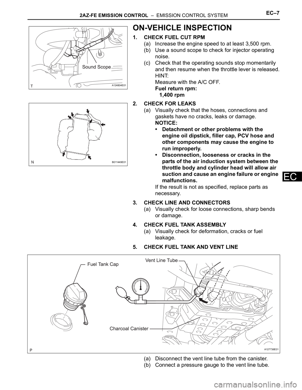
1. CHECK FUEL CUT RPM
(a) Increase the engine speed to at least 3,500 rpm.
(b) Use a sound scope to check for injector operating
noise.
(c) Check that the operating sounds stop momentarily
and then resume when the throttle lever is released.
HINT:
Measure with the A/C OFF.
Fuel return rpm:
1,400 rpm
2. CHECK FOR LEAKS
(a) Visually check that the hoses, connections and
gaskets have no cracks, leaks or damage.
NOTICE:
• Detachment or other problems with the
engine oil dipstick, filler cap, PCV hose and
other components may cause the engine to
run improperly.
• Disconnection, looseness or cracks in the
parts of the air induction system between the
throttle body and cylinder head will allow air
suction and cause an engine failure or engine
malfunctions.
If the result is not as specified, replace parts as
necessary.
3. CHECK LINE AND CONNECTORS
(a) Visually check for loose connections, sharp bends
or damage.
4. CHECK FUEL TANK ASSEMBLY
(a) Visually check for deformation, cracks or fuel
leakage.
5. CHECK FUEL TANK AND VENT LINE
(a) Disconnect the vent line tube from the canister.
(b) Connect a pressure gauge to the vent line tube.
A124804E01
B011449E01
A127736E01
Page 245 of 2000
2AZ-FE LUBRICATION – OIL PUMPLU–13
LU
INSPECTION
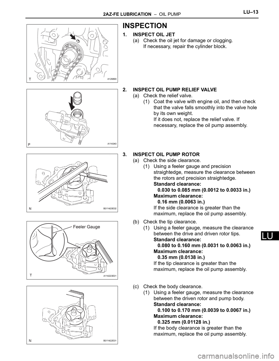
1. INSPECT OIL JET
(a) Check the oil jet for damage or clogging.
If necessary, repair the cylinder block.
2. INSPECT OIL PUMP RELIEF VALVE
(a) Check the relief valve.
(1) Coat the valve with engine oil, and then check
that the valve falls smoothly into the valve hole
by its own weight.
If it does not, replace the relief valve. If
necessary, replace the oil pump assembly.
3. INSPECT OIL PUMP ROTOR
(a) Check the side clearance.
(1) Using a feeler gauge and precision
straightedge, measure the clearance between
the rotors and precision straightedge.
Standard clearance:
0.030 to 0.085 mm (0.0012 to 0.0033 in.)
Maximum clearance:
0.16 mm (0.0063 in.)
If the side clearance is greater than the
maximum, replace the oil pump assembly.
(b) Check the tip clearance.
(1) Using a feeler gauge, measure the clearance
between the drive and driven rotor tips.
Standard clearance:
0.080 to 0.160 mm (0.0031 to 0.0063 in.)
Maximum clearance:
0.35 mm (0.0138 in.)
If the tip clearance is greater than the
maximum, replace the oil pump assembly.
(c) Check the body clearance.
(1) Using a feeler gauge, measure the clearance
between the driven rotor and pump body.
Standard clearance:
0.100 to 0.170 mm (0.0039 to 0.0067 in.)
Maximum clearance:
0.325 mm (0.01128 in.)
If the body clearance is greater than the
maximum, replace the oil pump assembly.
A126890
A114340
B011420E02
A114223E01
B011422E01
Page 248 of 2000
2GR-FE LUBRICATION – OIL PUMPLU–13
LU
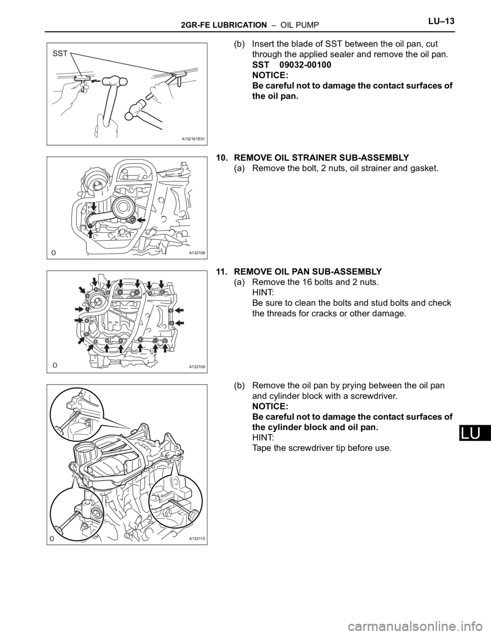
(b) Insert the blade of SST between the oil pan, cut
through the applied sealer and remove the oil pan.
SST 09032-00100
NOTICE:
Be careful not to damage the contact surfaces of
the oil pan.
10. REMOVE OIL STRAINER SUB-ASSEMBLY
(a) Remove the bolt, 2 nuts, oil strainer and gasket.
11. REMOVE OIL PAN SUB-ASSEMBLY
(a) Remove the 16 bolts and 2 nuts.
HINT:
Be sure to clean the bolts and stud bolts and check
the threads for cracks or other damage.
(b) Remove the oil pan by prying between the oil pan
and cylinder block with a screwdriver.
NOTICE:
Be careful not to damage the contact surfaces of
the cylinder block and oil pan.
HINT:
Tape the screwdriver tip before use.
A132161E01
A132108
A132109
A132110
Page 376 of 2000
AX–248U241E AUTOMATIC TRANSAXLE – UNDERDRIVE CLUTCH
AX
INSPECTION
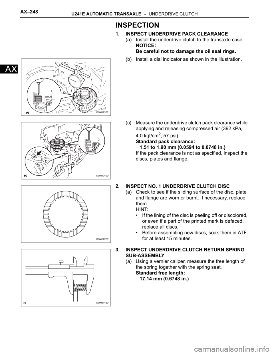
1. INSPECT UNDERDRIVE PACK CLEARANCE
(a) Install the underdrive clutch to the transaxle case.
NOTICE:
Be careful not to damage the oil seal rings.
(b) Install a dial indicator as shown in the illustration.
(c) Measure the underdrive clutch pack clearance while
applying and releasing compressed air (392 kPa,
4.0 kgf/cm
2, 57 psi).
Standard pack clearance:
1.51 to 1.90 mm (0.0594 to 0.0748 in.)
If the pack clearance is not as specified, inspect the
discs, plates and flange.
2. INSPECT NO. 1 UNDERDRIVE CLUTCH DISC
(a) Check to see if the sliding surface of the disc, plate
and flange are worn or burnt. If necessary, replace
them.
HINT:
• If the lining of the disc is peeling off or discolored,
or even if a part of the printed mark is defaced,
replace all discs.
• Before assembling new discs, soak them in ATF
for at least 15 minutes.
3. INSPECT UNDERDRIVE CLUTCH RETURN SPRING
SUB-ASSEMBLY
(a) Using a vernier caliper, measure the free length of
the spring together with the spring seat.
Standard free length:
17.14 mm (0.6748 in.)
D008123E01
D008124E01
D004077E01
D009214E01
Page 378 of 2000
AX–250U241E AUTOMATIC TRANSAXLE – UNDERDRIVE CLUTCH
AX
• This prevents the spring sheet from being
deformed.
• Do not expand the snap ring excessively.
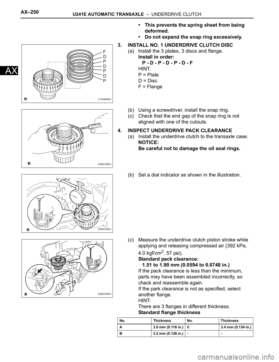
3. INSTALL NO. 1 UNDERDRIVE CLUTCH DISC
(a) Install the 3 plates, 3 discs and flange.
Install in order:
P - D - P - D - P - D - F
HINT:
P = Plate
D = Disc
F = Flange
(b) Using a screwdriver, install the snap ring.
(c) Check that the end gap of the snap ring is not
aligned with one of the cutouts.
4. INSPECT UNDERDRIVE PACK CLEARANCE
(a) Install the underdrive clutch to the transaxle case.
NOTICE:
Be careful not to damage the oil seal rings.
(b) Set a dial indicator as shown in the illustration.
(c) Measure the underdrive clutch piston stroke while
applying and releasing compressed air (392 kPa,
4.0 kgf/cm
2, 57 psi).
Standard pack clearance:
1.51 to 1.90 mm (0.0594 to 0.0748 in.)
If the pack clearance is less than the minimum,
parts may have been assembled incorrectly, so
check and reassemble again.
If the park clearance is not as specified, select
another flange.
HINT:
There are 3 flanges in different thickness.
Standard flange thickness
C129394E01
D008125E01
D008123E01
D008124E01
No. Thickness No. Thickness
A 3.0 mm (0.118 in.) C 3.4 mm (0.134 in.)
B 3.2 mm (0.126 in.) - -
Page 382 of 2000
GF1A TRANSFER – TRANSFER SYSTEMTF–3
TF
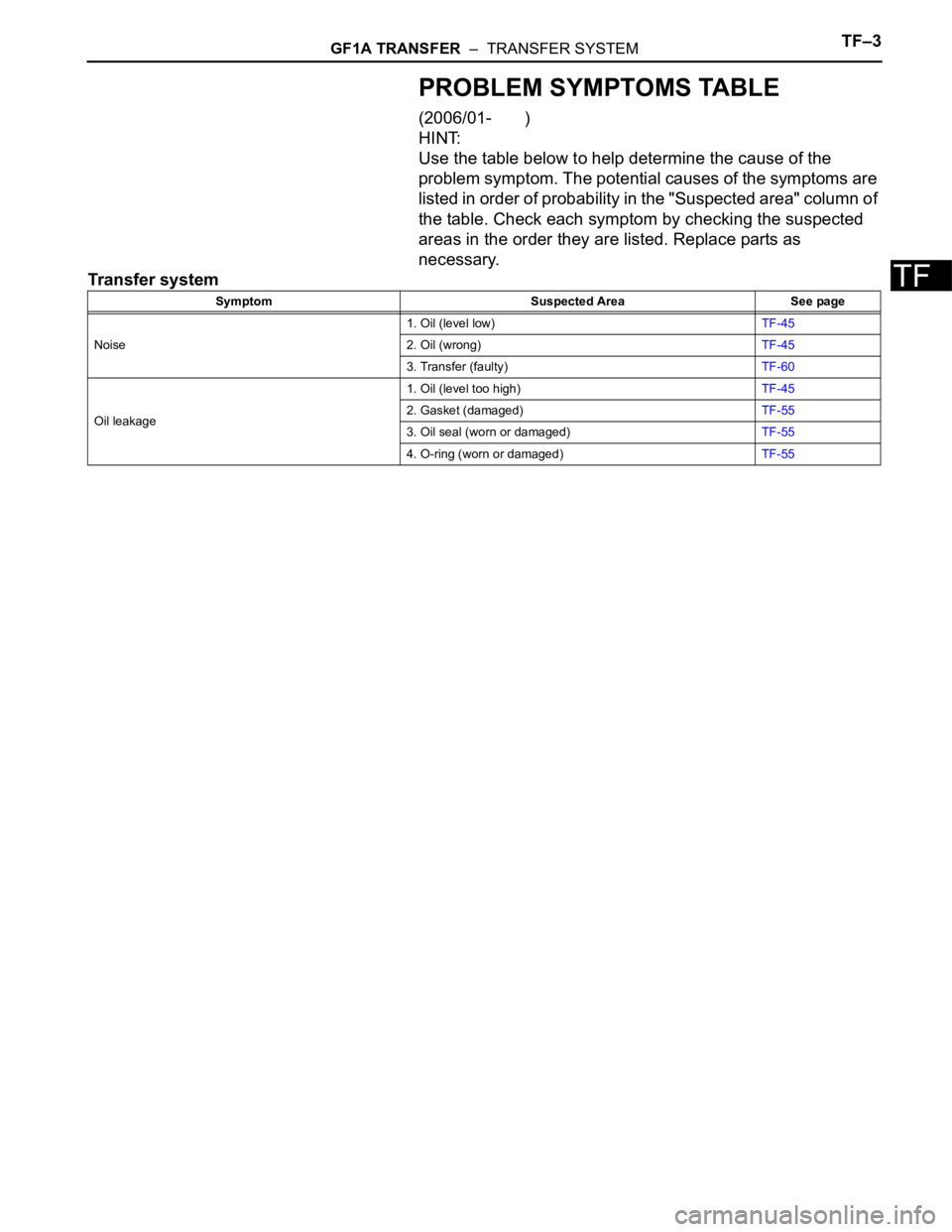
PROBLEM SYMPTOMS TABLE
(2006/01- )
HINT:
Use the table below to help determine the cause of the
problem symptom. The potential causes of the symptoms are
listed in order of probability in the "Suspected area" column of
the table. Check each symptom by checking the suspected
areas in the order they are listed. Replace parts as
necessary.
Transfer system
Symptom Suspected Area See page
Noise1. Oil (level low)TF-45
2. Oil (wrong)TF-45
3. Transfer (faulty)TF-60
Oil leakage1. Oil (level too high)TF-45
2. Gasket (damaged)TF-55
3. Oil seal (worn or damaged)TF-55
4. O-ring (worn or damaged)TF-55