key battery TOYOTA RAV4 2006 Service Repair Manual
[x] Cancel search | Manufacturer: TOYOTA, Model Year: 2006, Model line: RAV4, Model: TOYOTA RAV4 2006Pages: 2000, PDF Size: 45.84 MB
Page 30 of 2000

ENGINE - 2AZ-FE ENGINE
01MEG05Y
DEFGGER SWITCH
TA I L L I G H T S W I T C H
STOP LIGHT SWITCH
CURRENT SENSOR
CANISTER PUMP MODULE
CANISTER PRESSURE
SENSOR
TRANSPONDER KEY ECU*
AIRBAG SENSOR ASSEMBLY
EPS ECU
AIR CONDITIONING ECU
SKID CONTROL ECU
DLC3
BATTERYELS1
ELS3
STP
ST1-
THB
VCIB
PPMP
IMI
IMO
CANH,
CANL
TC
TA C H
BATTECMFA N H
FA N L
MPMP
VPMP
PRG
RLO
DF
MREL
+B
WCOOLING FAN CONTROL
COOLING FAN RELAY No.1
COOLING FAN RELAY No.2
COOLING FAN RELAY No.3
EVAPORATIVE EMISSION
CONTROL
CANISTER PUMP MODULE
LEAK DETECTION PUMP
VENT VALVE
GENERATOR
MAIN RELAY
COMBINATION METER
MIL
PURGE VSV
: CANEG-33
*: Models with Engine Immobilizer System
Page 100 of 2000

ENGINE - 2GR-FE ENGINE
01MEG06Y
COMBINATION METER
Vehicle Speed Signal
AIR-FUEL RATIO SENSOR
Bank 1, Sensor 1
Bank 2, Sensor 1
HEATED OXYGEN SENSOR
Bank 1, Sensor 2
Bank 2, Sensor 2
CANISTER PUMP MODULE
CANISTER PRESSURE
SENSOR
PARK / NEUTRAL POSITION
SWITCH
TRANSMISSION CONTROL
SWITCH
TRANSPONDER KEY ECU
GENERATOR
BATTERY CURRENT SENSOR
(BUILT-IN BATTERY
TEMPERATURE SENSOR)
WIPER CONTROL SWITCHSPD
A1A
A2A
OX1B
OX2B
PPMP
STA
P, R, N, D
4, L
IMI
IMO
DF
THB VCIB
INHECMACIS
AICV
FC
FPR
HA1A
HA2A
HT1B
HT2B
RLOACIS
ACIS ACTUATOR
AIR INTAKE CONTROL
SYSTEM
VSV
FUEL PUMP CONTROL
CIRCUIT OPENING RELAY
FUEL PUMP RELAY
AIR-FUEL RATIO SENSOR
HEATER CONTROL
AIR-FUEL RATIO SENSOR
HEATER
Bank 1, Sensor 1
Bank 2, Sensor 1
HEATED OXYGEN SENSOR
HEATER CONTROL
HEATED OXYGEN SENSOR
HEATER
Bank 1, Sensor 2
Bank 2, Sensor 2
CHARGING CONTROL
GENERATOR EG-104
(Continued)
Page 453 of 2000

LI–126LIGHTING – IGNITION KEY CYLINDER LIGHT
LI
INSTALLATION
1. INSTALL TRANSPONDER KEY AMPLIFIER (See page
SR-18)
2. INSTALL STEERING COLUMN COVER (See page SR-
20)
3. INSTALL STEERING WHEEL ASSEMBLY (See page
SR-21)
4. PLACE FRONT WHEELS FACING STRAIGHT AHEAD
5. INSPECT STEERING WHEEL CENTER POINT
6. INSTALL STEERING PAD ASSEMBLY (See page RS-
336)
7. CONNECT CABLE TO NEGATIVE BATTERY
TERMINAL
8. INSPECT STEERING PAD ASSEMBLY (See page RS-
337)
9. CHECK SRS WARNING LIGHT
(a) Check the SRS warning light (see page RS-337).
Page 908 of 2000

2AZ-FE STARTING – IGNITION SWITCHST–19
ST
If the result is not as specified, replace the switch
assembly.
INSTALLATION
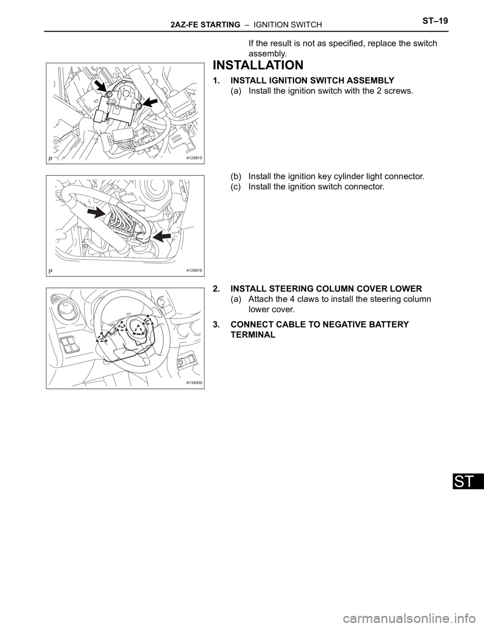
1. INSTALL IGNITION SWITCH ASSEMBLY
(a) Install the ignition switch with the 2 screws.
(b) Install the ignition key cylinder light connector.
(c) Install the ignition switch connector.
2. INSTALL STEERING COLUMN COVER LOWER
(a) Attach the 4 claws to install the steering column
lower cover.
3. CONNECT CABLE TO NEGATIVE BATTERY
TERMINAL
A124915
A124916
A134309
Page 919 of 2000

2GR-FE STARTING – IGNITION SWITCHST–19
ST
INSTALLATION
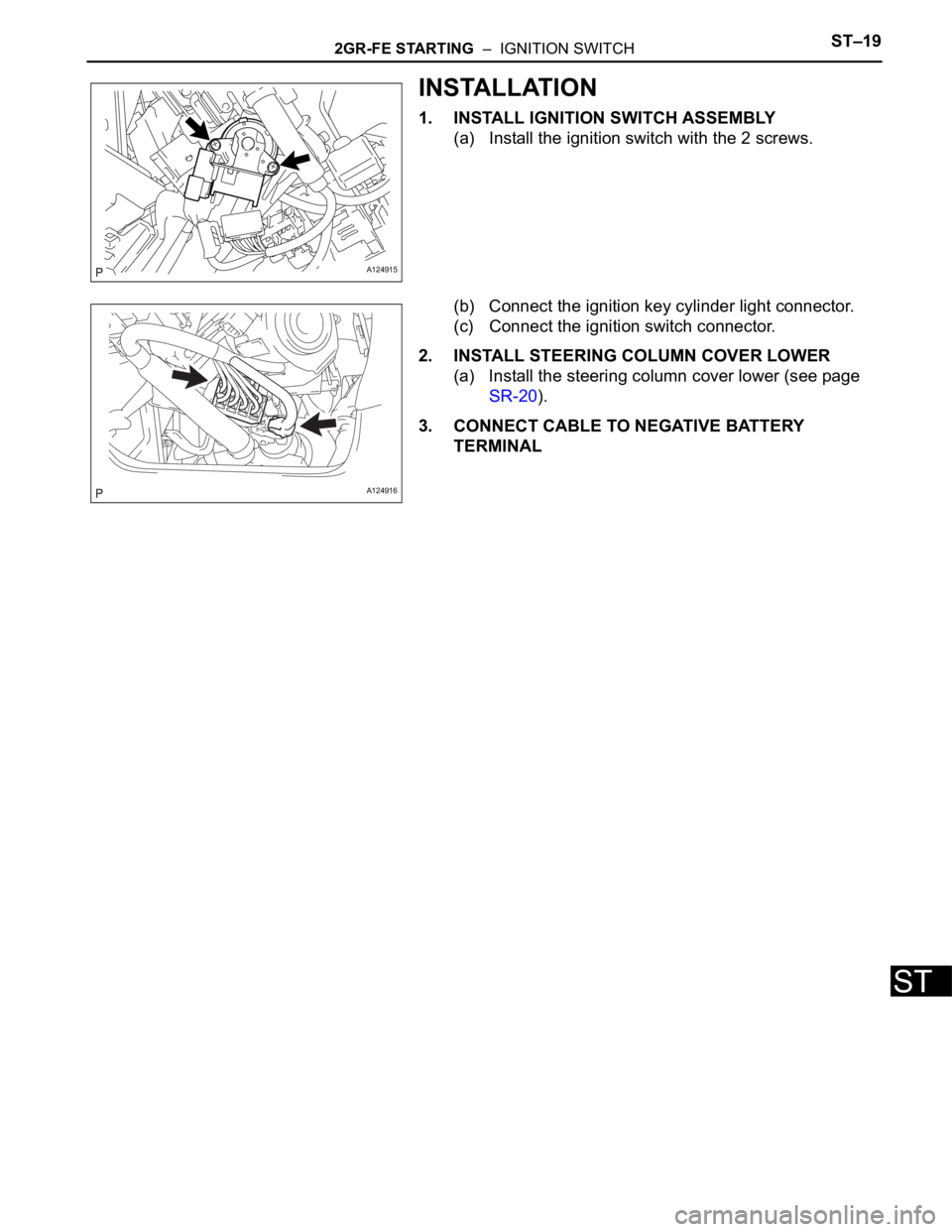
1. INSTALL IGNITION SWITCH ASSEMBLY
(a) Install the ignition switch with the 2 screws.
(b) Connect the ignition key cylinder light connector.
(c) Connect the ignition switch connector.
2. INSTALL STEERING COLUMN COVER LOWER
(a) Install the steering column cover lower (see page
SR-20).
3. CONNECT CABLE TO NEGATIVE BATTERY
TERMINAL
A124915
A124916
Page 1778 of 2000

ENGINE IMMOBILISER – ENGINE IMMOBILISER SYSTEMEI–7
EI
HINT:
• In this mode, a maximum of 3 key codes for 2
master keys and 1 sub-key can be registered.
The master keys and sub-key can be registered
in any order because the transponder key ECU
can distinguish between different types of keys.
• New key codes must be registered with the
battery connected. The ignition switch can be
either ON or OFF.
• When a new transponder key ECU is installed,
key codes must be registered in the transponder
key ECU.
HINT:
• The new key code registration mode can be
deliberately ended by following procedure A or B
below when the battery is connected, and at
least 1 key code for the master key has been
registered.
(a) Insert the key into the ignition key cylinder and
turn the intelligent tester on.
(b) Follow the instructions on the intelligent tester
screen to end the new key code registration
mode.
(c) New key code registration mode ends.
• When the engine immobiliser system is operating
normally and the key is pulled out, the security
indicator light blinks continuously.
• If the new key code registration fails, code 2-1 is
output by the security indicator light. Trying to re-
register an already registered key causes code
2-2 to be output when the key is inserted. If the
number of registered key codes exceeds the
limit, code 2-3 is output by the security indicator
light. The output details are shown below.
Procedure Security Indicator Light Condition
1. START-
HINT:
Until first key is inserted
2. Insert key into the ignition key cylinder BLINKING
3. Select following items on the tester:
(1) IMMOBILISER
(2) ID UTILITY
(3) IMMOB CODE REG
HINT:
After above operation, proceed to next step in accordance with
prompts on tester screenON
HINT:
Within 2 minutes
OFF for 1 second and then ON
4. Remove the key and then push NEXT button on tester ON
5. Insert master key or sub-key to be registered OFF for 1 second and then ON
6. Remove key and then push NEXT button on tester ON
7. Insert a master key or sub-key to be registeredOFF for 1 second and then ON
OFF
HINT:
0.5 seconds after turning ON
8. Remove key BLINKING
9. END
Page 1780 of 2000

ENGINE IMMOBILISER – ENGINE IMMOBILISER SYSTEMEI–9
EI
3. REGISTRATION OF ADDITIONAL KEY (PROCEDURE
"A")
HINT:
• A maximum of 5 master key codes and 3 sub-key
codes can be registered.
• Additional key code registration mode ends if each
step is not completed within the specified time.
• When proceeding to the next step while the timer is
running, the timer is reset and begins the countdown
for the next step.
• When the ignition key cylinder or the ignition key
cylinder set is replaced, remove the transmitter
module from the original master key. Then install this
transmitter module to a new key and use the new key
as the master key. If necessary, use this master key to
register other keys.
NOTICE:
When the ignition key cylinder has been replaced,
locking and unlocking doors are possible with the
new master key once the transmitter module from
the original master key has been transferred to it.
However, the new master key will not be able to lock
and unlock doors through the door key cylinder.
Keep the original master key. If the new master key's
transmitter module battery fails, the original master
key can be used to lock and unlock doors through
the door key cylinder.
(a) Additional key code registration
Condition:
At least one key code must be registered in the
transponder key ECU.
ProcedureTime
(Operation completion time)Security Indicator Light Condition
1. START -BLINKING
HINT:
Until first key is inserted
2. Insert previously registered master key into
ignition key cylinder, turn ignition switch to ON
position, and turn intelligent tester on
-OFF
3. Select the following items on the tester:
(1) IMMOBILISER
(2) ID UTILITY
(3) IMMOB CODE REGON
4. Remove master key and then push NEXT
button on tester. Immediately after above
operation, insert previously registered master
key into ignition key cylinder, turn ignition
switch to ON position, and then push NEXT
button on tester.Within 120 seconds BLINKING
ON
5. Remove master key and then push NEXT
button on testerWithin 20 seconds
HINT:
After the tester instruction.ON
6. Insert key to be registered into ignition key
cylinderWithin 10 seconds. BLINKING
Page 1782 of 2000

ENGINE IMMOBILISER – ENGINE IMMOBILISER SYSTEMEI–11
EI
HINT:
• To cancel erasure mode after the erasure
request is sent from the tester to the ECU, leave
the master key inserted until the timer times out.
• A brief outline of the procedures for key code
erasure is shown above. For more detailed
information, refer to the intelligent tester screen's
instructions.
• When the engine immobiliser system is operating
normally and the key is pulled out, the security
indicator light blinks continuously.
5. ECU - ECM COMMUNICATION ID REGISTRATION
(PROCEDURE "C")
NOTICE:
• The ECU communication ID should be registered
when the transponder key ECU and / or ECM is
replaced in order to match the ECU - ECM
communication ID.
• The engine cannot be started unless the ECU -
ECM communication ID matches.
• Do not disconnect the battery while the ECU -
ECM communication ID is being set.
• Do not turn the ignition switch from ON to OFF 20
times or more before setting the ECU - ECM
communication ID. If this operation is likely to be
performed 20 times or more, disconnect the
negative battery terminal cable in order to avoid
engine start disablement. Failure to do so will
result in the engine not starting unless the
transponder key ECU is replaced with a new one.
(a) After replacing the transponder key ECU
(1) Register the key code(s) by following the new
key code registration procedure (procedure
"B").
(2) Using SST, connect the TC and CG terminals
of the DLC3 before inserting the key into the
key cylinder.
SST 09843-18040
5. Remove master keyWithin 10 seconds
HINT:
After tester instructionBLINKING
6. ENDProcedureTime
(Operation completion time)Security Indicator Light Condition
Page 1786 of 2000

ENGINE IMMOBILISER – ENGINE IMMOBILISER SYSTEMEI–15
EI
(f) Using an oscilloscope, check the waveform 2.
Waveform 2 (Reference):
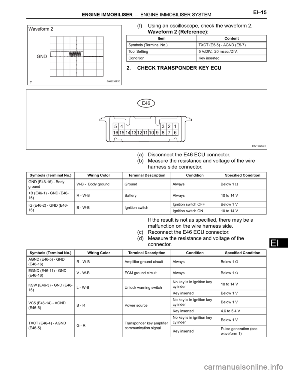
2. CHECK TRANSPONDER KEY ECU
(a) Disconnect the E46 ECU connector.
(b) Measure the resistance and voltage of the wire
harness side connector.
If the result is not as specified, there may be a
malfunction on the wire harness side.
(c) Reconnect the E46 ECU connector.
(d) Measure the resistance and voltage of the
connector.
B069239E10
Item Content
Symbols (Terminal No.) TXCT (E5-5) - AGND (E5-7)
Tool Setting 5 V/DIV., 20 msec./DIV.
Condition Key inserted
B121962E04
Symbols (Terminal No.) Wiring Color Terminal Description ConditionSpecified Condition
GND (E46-16) - Body
groundW-B - Body ground Ground Always Below 1
+B (E46-1) - GND (E46-
16)R - W-B Battery Always 10 to 14 V
IG (E46-2) - GND (E46-
16)B - W-B Ignition switchIgnition switch OFF Below 1 V
Ignition switch ON 10 to 14 V
Symbols (Terminal No.) Wiring Color Terminal Description ConditionSpecified Condition
AGND (E46-5) - GND
(E46-16)R - W-B Amplifier ground circuit Always Below 1
EGND (E46-11) - GND
(E46-16)V - W-B ECM ground circuit Always Below 1
KSW (E46-3) - GND (E46-
16)L - W-B Unlock warning switchNo key is in ignition key
cylinder10 to 14 V
Key inserted Below 1 V
VC5 (E46-14) - AGND
(E46-5)B - R Power sourceNo key is in ignition key
cylinderBelow 1 V
Key inserted 4.6 to 5.4 V
TXCT (E46-4) - AGND
(E46-5)G - RTransponder key amplifier
communication signalNo key is in ignition key
cylinderBelow 1 V
Key insertedPulse generation (see
waveform 1)
Page 1793 of 2000

EI–22ENGINE IMMOBILISER – ENGINE IMMOBILISER SYSTEM
EI
2. PERFORM ACTIVE TEST
HINT:
Performing the intelligent tester's ACTIVE TEST allows
relay, VSV, actuator and other items to be operated
without removing any parts. Performing the ACTIVE
TEST early in troubleshooting is one way to save time.
The DATA LIST can be displayed during the ACTIVE
TEST.
(a) Connect the intelligent tester (with CAN VIM) to the
DLC3.
(b) Turn the ignition switch ON and turn the tester ON.
(c) Select the following menu items: DIAGNOSIS /
OBD/MOBD / IMMOBILISER / ACTIVE TEST.
(d) Perform the ACTIVE TEST by referring to the table
below.
Transponder key ECU:
+B+B judgment / NORMAL or
BREAKNORMAL: Battery supply is
normal
BREAK: Battery supply is
malfunctioning-
ANTENNA COILTransponder key coil condition /
NORMAL or FAILNORMAL: Transponder key coil
is normal
FAIL: Transponder key coil is
malfunctioning- ItemMeasurement Item / Display
(Range)Normal Condition Diagnostic Note
Item Test Details Diagnostic Note
SECURITY INDIC Turns security indicator light / ON or OFF -