oil pressure TOYOTA RAV4 2006 Service Repair Manual
[x] Cancel search | Manufacturer: TOYOTA, Model Year: 2006, Model line: RAV4, Model: TOYOTA RAV4 2006Pages: 2000, PDF Size: 45.84 MB
Page 4 of 2000

ENGINE - 2AZ-FE ENGINE
DR011EG22 01NEG26Y
Air Flow During Engine Revolution
Wa t e r P u m p
Swirl Chamber
Crankshaft
Bearing Cap
Plastic Region
Tightening BoltsThermostat Housing
Air Conditioning
Compressor BracketsAir Passage Holes
Air Flow
NOTICE
Never attempt to machine the cylinder because it has a thin liner thickness.
EG-7
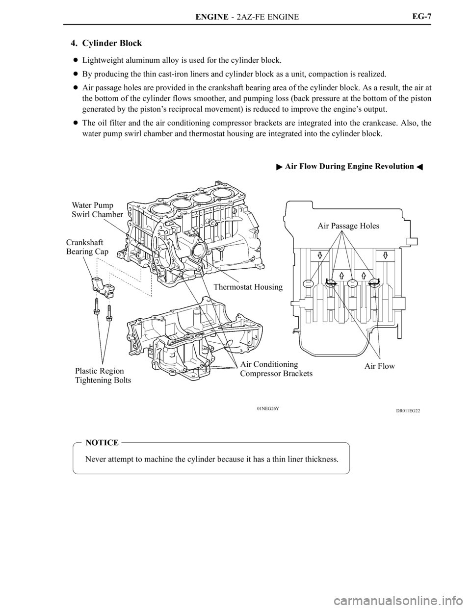
4. Cylinder Block
Lightweight aluminum alloy is used for the cylinder block.
By producing the thin cast-iron liners and cylinder block as a unit, compaction is realized.
Air passage holes are provided in the crankshaft bearing area of the cylinder block. As a result, the air at
the bottom of the cylinder flows smoother, and pumping loss (back pressure at the bottom of the piston
generated by the piston’s reciprocal movement) is reduced to improve the engine’s output.
The oil filter and the air conditioning compressor brackets are integrated into the crankcase. Also, the
water pump swirl chamber and thermostat housing are integrated into the cylinder block.
Page 10 of 2000

ENGINE - 2AZ-FE ENGINE
181EG11
VVT-i ControllerIntake CamshaftTiming Rotor
Exhaust Camshaft
Timing Sprocket
185EG25 181EG14
Cam Spring
Cam
Plunger
SpringChain
Te n s i o n e r
Chain Damper
Oil Jet
Chain TensionerChain SlipperEG-13
2. Camshaft
The intake camshaft is provided with timing rotor to trigger the camshaft position sensor.
In conjunction with the adoption of the VVT-i system, an oil passage is provided in the intake camshaft
in order to supply engine oil pressure to the VVT-i system.
A VVT-i controller has been installed on the front of the intake camshaft to vary the timing of the intake
valves.
3. Timing Chain
A roller chain with an 8 mm (0.315 in.) pitch is used to make the engine more compact.
The timing chain is lubricated by an oil jet.
The chain tensioner uses a spring and oil pressure to maintain proper chain tension at all times.
The chain tensioner suppresses noise generated by the timing chain.
A ratchet type non-return mechanism is used.
To achieve excellent serviceability, the chain tensioner is constructed so that it can be removed and
installed from the outside of the timing chain cover.
Page 12 of 2000

ENGINE - 2AZ-FE ENGINE
01NEG34Y
Oil Jets
Check
Va l v e
Oil
Bottom Side View Oil Jet Cross SectionEG-15
Oil Capacity
Liters (US qts, Imp. qts)
Dry
5.0 (5.3, 4.4)
with Oil Filter4.3 (4.5, 3.8)
without Oil Filter4.1 (3.8, 3.1)
2. Oil Jet
Piston oil jets for cooling and lubricating the pistons are used in the cylinder block.
These oil jets contain a check valve to prevent oil from being fed when the oil pressure is low. This prevents
the overall oil pressure in the engine from dropping.
Page 31 of 2000

ENGINE - 2AZ-FE ENGINE
01MEG09Y
Accelerator Pedal
Position Sensor
Generator
MIL
DLC3Park / Neutral
Position Switch
Ignition
Switch
Circuit Opening RelayECM
Battery
Throttle
Position
Sensor
Throttle
Control
Motor
Purge VSVMass Air Flow Meter
Intake Air Temperature
Sensor
Camshaft Position
Sensor
Camshaft
Timing
Oil Control
Va l v e
Ignition Coil
with Igniter
Injector
Knock Sensor
Engine
Coolant
Temperature
Sensor
Crankshaft Position
Sensor
Canister
Filter
Fuel Pump
Canister Pump Module
Ve n t Va l v e
Leak Detection Pump
Canister Pressure SensorTWCs
Heated Oxygen Sensor
(Bank 1, Sensor 2)
Air-fuel Ratio Sensor
(Bank 1, Sensor 1) EG-34
3. Engine Control System Diagram
Page 32 of 2000

ENGINE - 2AZ-FE ENGINE
01MEG31Y
DLC3
Accelerator Pedal
Position Sensor
Mass Air Flow Meter
(Built-in Intake Air
Temperature Sensor)
VSV (for EVAP)
Battery Current
Sensor
Fuel Pump
Canister Pump Module
Ve n t Va l v e
Leak Detection Pump
Canister Pressure Sensor
ECM
Heated Oxygen Sensor
(Bank 1, Sensor 2) Air Fuel Ratio Sensor
(Bank 1, Sensor 1)
Camshaft Timing
Oil Control ValveInjectorKnock Sensor
Ignition Coil with Igniter
Throttle Position
Sensor
Camshaft Position
Sensor
Water Temperature
Sensor
Crakshaft Position
SensorEG-35
4. Layout of Main Components
Page 47 of 2000

ENGINE - 2AZ-FE ENGINE
169EG36
HousingLock Pin
Intake Camshaft
Vane (Fixed on Intake Camshaft)
Oil Pressure
At a Stop In Operation
Lock Pin
221EG17
To VVT-i Controller
(Advance Side)To V V T- i C o n t r o l l e r
(Retard Side)
Sleeve
Spring
Drain
Oil PressureDrain
Spool ValveCoil
Plunger EG-50
Construction
1) VVT-i Controller
This controller consists of the housing driven by the timing chain and the vane fixed on the intake
camshaft.
The oil pressure sent from the advance or retard side path at the intake camshaft causes rotation in the
VVT-i controller vane circumferential direction to vary the intake valve timing continuously.
When the engine is stopped, the intake camshaft will be in the most retarded state to ensure startability.
When hydraulic pressure is not applied to the VVT-i controller immediately after the engine has been
started, the lock pin locks the movement of the VVT-i controller to prevent a knocking noise.
2) Camshaft Timing Oil Control Valve
This camshaft timing oil control valve controls the spool valve position in accordance with the duty-cycle
control from the ECM. This allows hydraulic pressure to be applied to the VVT-i controller advance or
retard sides. When the engine is stopped, the camshaft timing oil control valve is in the most retarded
state.
Page 48 of 2000

ENGINE - 2AZ-FE ENGINE
198EG35
Va n e
Rotation DirectionOil PressureECM
IN Drain
198EG36
Va n e
Rotation DirectionOil Pressure
Drain INECMEG-51
Operation
1) Advance
When the camshaft timing oil control valve is operated as illustrated below by the advance signals from
the ECM, the resultant oil pressure is applied to the advance side vane chamber to rotate the camshaft
in the advance direction.
2) Retard
When the camshaft timing oil control valve is operated as illustrated below by the retard signals from
the ECM, the resultant oil pressure is applied to the retard side vane chamber to rotate the camshaft in
the retard direction.
3) Hold
After reaching the target timing, the valve timing is held by keeping the camshaft timing oil control valve
in the neutral position unless the traveling state changes.
This adjusts the valve timing at the desired target position and prevents the engine oil from running out
when it is unnecessary.
Page 76 of 2000

ENGINE - 2GR-FE ENGINE
285EG18
Secondary
Timing
ChainExhaust Camshaft Intake CamshaftsExhaust Camshaft
Roller Rocker Arm
Va l v e S p r i n g
Retainer
Va l v e S p r i n g
Hydraulic
Lash Adjuster
Va l v e G u i d e
Bush Va l v e S p r i n g
Sheet
Va l v e
Secondary Timing
Chain Primary
Timing
Chain EG-80
VA LV E M E C H A N I S M
1. General
Each cylinder of this engine has 2 intake valves and 2 exhaust valves. Intake and exhaust efficiency is
increased due to the larger total port areas.
This engine uses roller rocker arms with built-in needle bearings. This reduces the friction that occurs
between the cams and the areas (roller rocker arms) that push the valves down, thus improving fuel
economy.
A hydraulic lash adjuster, which maintains a constant zero valve clearance through the use of oil pressure
and spring force, is used.
The intake camshafts are driven by the crankshaft via the primary timing chain. The exhaust camshafts
are driven by the intake camshaft of the respective bank via the secondary timing chain.
This engine uses a Dual VVT-i (Variable Valve Timing-intelligent) system which controls the intake and
exhaust camshafts to provide optimal valve timing according to driving conditions. With this adoption,
lower fuel consumption, higher engine performance, and fewer exhaust emissions have been achieved.
For details of Dual VVT-i control, see page EG-120.
Page 78 of 2000

ENGINE - 2GR-FE ENGINE
285EG20
Secondary Chain Tensioner
Primary Chain TensionerSecondary
Timing Chain
Idle Sprocket Secondary Chain
Te n s i o n e r
Secondary
Timing Chain Secondary Chain
Te n s i o n e r
Chain Damper
Timing Chain Oil Jet
Primary Timing Chain Chain
Slipper Ball
Ball
SpringMain Spring
Plunger
SpringPlunger
Cam
Cam Spring EG-82
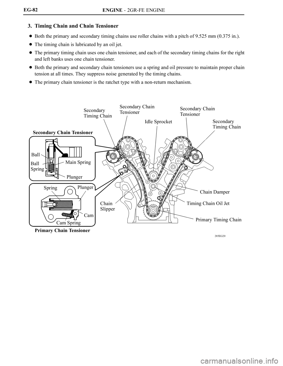
3. Timing Chain and Chain Tensioner
Both the primary and secondary timing chains use roller chains with a pitch of 9.525 mm (0.375 in.).
The timing chain is lubricated by an oil jet.
The primary timing chain uses one chain tensioner, and each of the secondary timing chains for the right
and left banks uses one chain tensioner.
Both the primary and secondary chain tensioners use a spring and oil pressure to maintain proper chain
tension at all times. They suppress noise generated by the timing chains.
The primary chain tensioner is the ratchet type with a non-return mechanism.
Page 79 of 2000

ENGINE - 2GR-FE ENGINE
285EG21
Timing Chain Cover
Wa t e r P u m p G a s k e t
Wa t e r P u m pWater Pump Swirl
Chamber
Oil Pump
Housing
Oil Pump RotorsTiming Chain
Cover
Oil Pump Chamber
View from Front Side View from Back Side
285EG22
Oil
Passage
Check Ball
Check Ball
Spring
Plunger SpringPlunger
Roller Rocker ArmCam
Oil
Passage
Hydraulic
Lash Adjuster
Service Tip
Valve clearance adjustment is not necessary because a hydraulic lash adjuster is used in this model.
EG-83
4. Timing Chain Cover
The timing chain cover has an integrated construction consisting of the cooling system (water pump and
water passage) and the lubrication system (oil pump and oil passage). Thus, the number of parts has been
reduced to reduce weight.
5. Hydraulic Lash Adjuster
The hydraulic lash adjuster, which is located at the fulcrum of the roller rocker arm, consists primarily of
a plunger, plunger spring, check ball, and check ball spring.
The engine oil that is supplied by the cylinder head and the built-in spring actuates the hydraulic lash
adjuster. The oil pressure and the spring force that act on the plunger push the roller rocker arm against
the cam, in order to adjust the valve clearance that is created during the opening and closing of the valve.
As a result, engine noise is reduced.