timing belt TOYOTA RAV4 2006 Service Repair Manual
[x] Cancel search | Manufacturer: TOYOTA, Model Year: 2006, Model line: RAV4, Model: TOYOTA RAV4 2006Pages: 2000, PDF Size: 45.84 MB
Page 204 of 2000
2GR-FE ENGINE MECHANICAL – ENGINE ASSEMBLYEM–29
EM
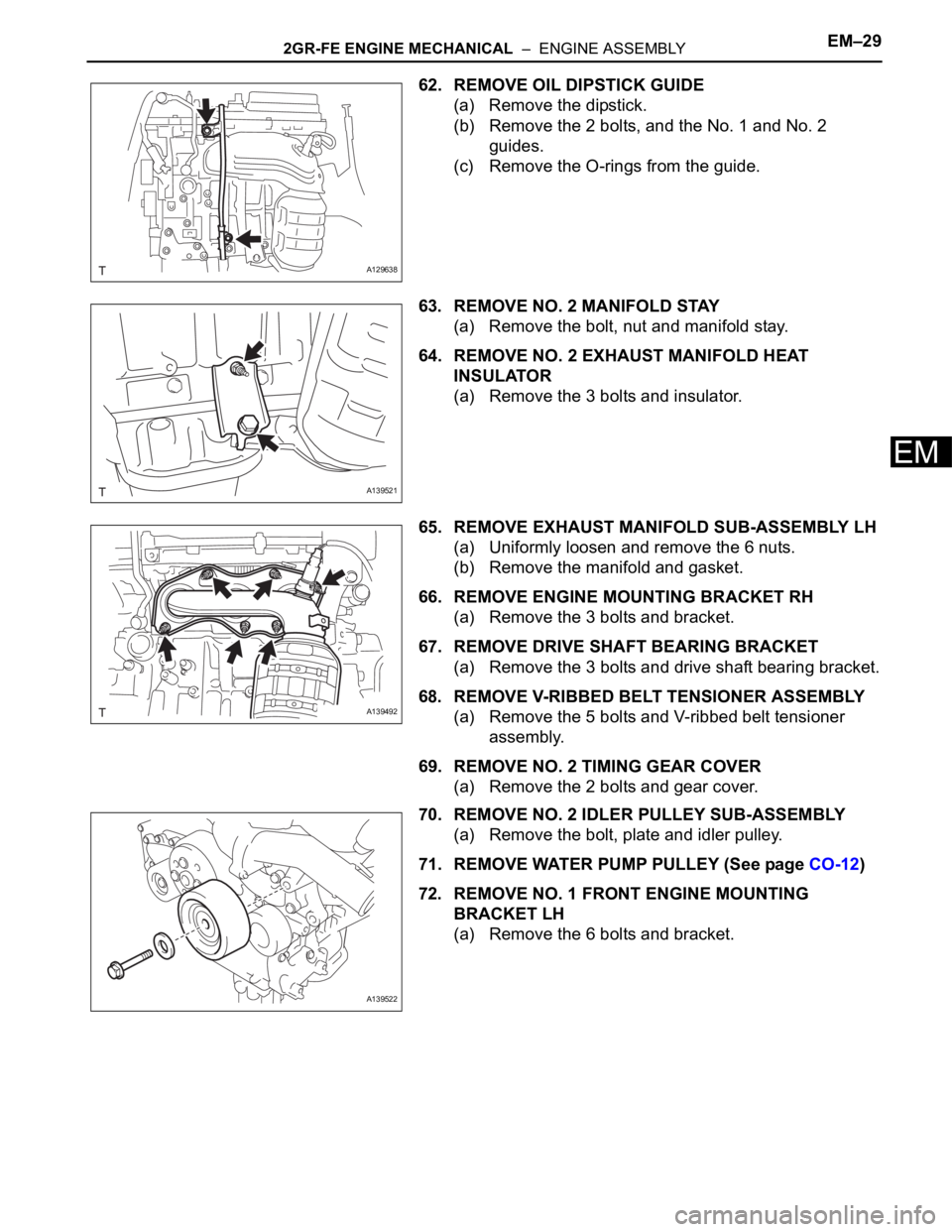
62. REMOVE OIL DIPSTICK GUIDE
(a) Remove the dipstick.
(b) Remove the 2 bolts, and the No. 1 and No. 2
guides.
(c) Remove the O-rings from the guide.
63. REMOVE NO. 2 MANIFOLD STAY
(a) Remove the bolt, nut and manifold stay.
64. REMOVE NO. 2 EXHAUST MANIFOLD HEAT
INSULATOR
(a) Remove the 3 bolts and insulator.
65. REMOVE EXHAUST MANIFOLD SUB-ASSEMBLY LH
(a) Uniformly loosen and remove the 6 nuts.
(b) Remove the manifold and gasket.
66. REMOVE ENGINE MOUNTING BRACKET RH
(a) Remove the 3 bolts and bracket.
67. REMOVE DRIVE SHAFT BEARING BRACKET
(a) Remove the 3 bolts and drive shaft bearing bracket.
68. REMOVE V-RIBBED BELT TENSIONER ASSEMBLY
(a) Remove the 5 bolts and V-ribbed belt tensioner
assembly.
69. REMOVE NO. 2 TIMING GEAR COVER
(a) Remove the 2 bolts and gear cover.
70. REMOVE NO. 2 IDLER PULLEY SUB-ASSEMBLY
(a) Remove the bolt, plate and idler pulley.
71. REMOVE WATER PUMP PULLEY (See page CO-12)
72. REMOVE NO. 1 FRONT ENGINE MOUNTING
BRACKET LH
(a) Remove the 6 bolts and bracket.
A129638
A139521
A139492
A139522
Page 379 of 2000
SS–12SERVICE SPECIFICATIONS – 2AZ-FE ENGINE MECHANICAL
SS
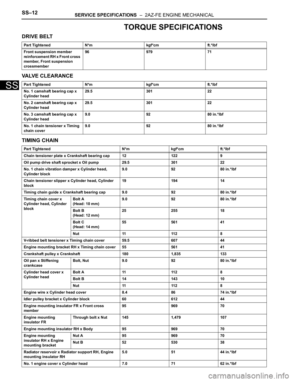
TORQUE SPECIFICATIONS
DRIVE BELT
VALVE CLEARANCE
TIMING CHAIN
Part Tightened N*m kgf*cm ft.*lbf
Front suspension member
reinforcement RH x Front cross
member, Front suspension
crossmember96 979 71
Part Tightened N*m kgf*cm ft.*lbf
No. 1 camshaft bearing cap x
Cylinder head29.5 301 22
No. 2 camshaft bearing cap x
Cylinder head29.5 301 22
No. 3 camshaft bearing cap x
Cylinder head9.0 92 80 in.*lbf
No. 1 chain tensioner x Timing
chain cover9.0 92 80 in.*lbf
Part Tightened N*m kgf*cm ft.*lbf
Chain tensioner plate x Crankshaft bearing cap 12 122 9
Oil pump drive shaft sprocket x Oil pump 29.5 301 22
No. 1 chain vibration damper x Cylinder head,
Cylinder block9.0 92 80 in.*lbf
Chain tensioner slipper x Cylinder head, Cylinder
block19 194 14
Timing chain guide x Crankshaft bearing cap 9.0 92 80 in.*lbf
Timing chain cover x
Cylinder head, Cylinder
blockBolt A
(Head: 10 mm)9.0 92 80 in.*lbf
Bolt B
(Head: 12 mm)25 255 18
Bolt C
(Head: 14 mm)55 561 41
Nut 11 112 8
V-ribbed belt tensioner x Timing chain cover 59.5 607 44
Engine mounting bracket RH x Timing chain cover 55 561 41
Crankshaft pulley x Crankshaft 180 1,835 133
Oil pan x Stiffening
crankcaseBolt, Nut 9.0 92 80 in.*lbf
Cylinder head cover x
Cylinder headBolt A 11 112 8
Bolt B 14 143 10
Nut 11 112 8
Engine wire x Cylinder head cover 8.4 86 74 in.*lbf
Idler pulley bracket x Cylinder block 60 612 44
Engine mounting insulator FR x Front cross
member95 969 70
Engine mounting
insulator FRThrough bolt x Nut 145 1,479 107
Engine mounting insulator RH x Body 95 969 70
Engine mounting
insulator RH x Engine
mounting bracketNut A 95 969 70
Nut B 52 530 38
Radiator reservoir x Radiator support RH, Engine
mounting insulator RH5.0 51 44 in.*lbf
No. 1 engine cover x Cylinder head 7.0 71 62 in.*lbf
Page 383 of 2000
SERVICE SPECIFICATIONS – 2GR-FE ENGINE MECHANICALSS–21
SS
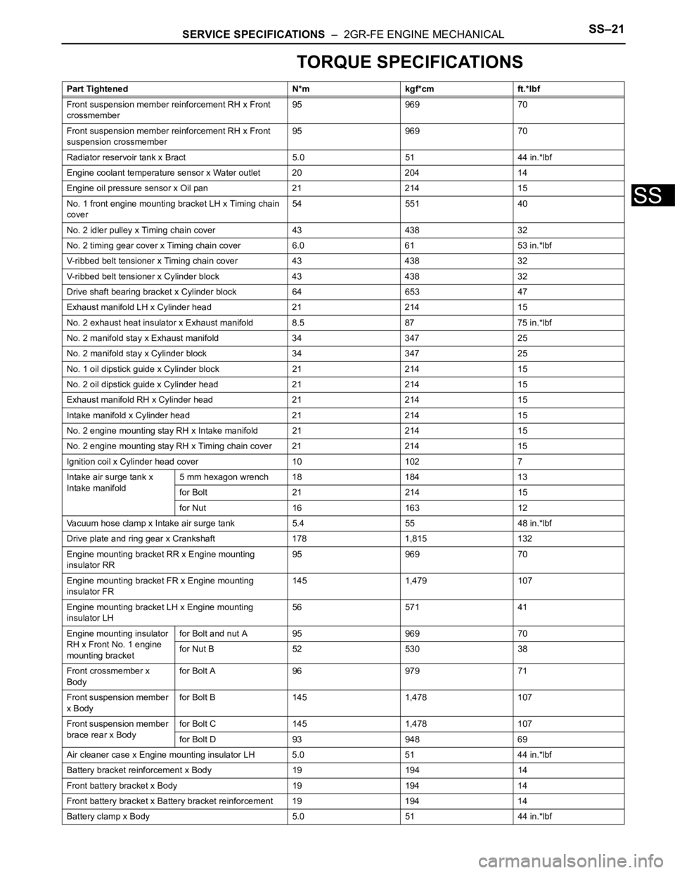
TORQUE SPECIFICATIONS
Part Tightened N*m kgf*cm ft.*lbf
Front suspension member reinforcement RH x Front
crossmember95 969 70
Front suspension member reinforcement RH x Front
suspension crossmember95 969 70
Radiator reservoir tank x Bract 5.0 51 44 in.*lbf
Engine coolant temperature sensor x Water outlet 20 204 14
Engine oil pressure sensor x Oil pan 21 214 15
No. 1 front engine mounting bracket LH x Timing chain
cover54 551 40
No. 2 idler pulley x Timing chain cover 43 438 32
No. 2 timing gear cover x Timing chain cover 6.0 61 53 in.*lbf
V-ribbed belt tensioner x Timing chain cover 43 438 32
V-ribbed belt tensioner x Cylinder block 43 438 32
Drive shaft bearing bracket x Cylinder block 64 653 47
Exhaust manifold LH x Cylinder head 21 214 15
No. 2 exhaust heat insulator x Exhaust manifold 8.5 87 75 in.*lbf
No. 2 manifold stay x Exhaust manifold 34 347 25
No. 2 manifold stay x Cylinder block 34 347 25
No. 1 oil dipstick guide x Cylinder block 21 214 15
No. 2 oil dipstick guide x Cylinder head 21 214 15
Exhaust manifold RH x Cylinder head 21 214 15
Intake manifold x Cylinder head 21 214 15
No. 2 engine mounting stay RH x Intake manifold 21 214 15
No. 2 engine mounting stay RH x Timing chain cover 21 214 15
Ignition coil x Cylinder head cover 10 102 7
Intake air surge tank x
Intake manifold5 mm hexagon wrench 18 184 13
for Bolt 21 214 15
for Nut 16 163 12
Vacuum hose clamp x Intake air surge tank 5.4 55 48 in.*lbf
Drive plate and ring gear x Crankshaft 178 1,815 132
Engine mounting bracket RR x Engine mounting
insulator RR95 969 70
Engine mounting bracket FR x Engine mounting
insulator FR145 1,479 107
Engine mounting bracket LH x Engine mounting
insulator LH56 571 41
Engine mounting insulator
RH x Front No. 1 engine
mounting bracketfor Bolt and nut A 95 969 70
for Nut B 52 530 38
Front crossmember x
Bodyfor Bolt A 96 979 71
Front suspension member
x Bodyfor Bolt B 145 1,478 107
Front suspension member
brace rear x Bodyfor Bolt C 145 1,478 107
for Bolt D 93 948 69
Air cleaner case x Engine mounting insulator LH 5.0 51 44 in.*lbf
Battery bracket reinforcement x Body 19 194 14
Front battery bracket x Body 19 194 14
Front battery bracket x Battery bracket reinforcement 19 194 14
Battery clamp x Body 5.0 51 44 in.*lbf
Page 579 of 2000
EM–222AZ-FE ENGINE MECHANICAL – TIMING CHAIN
EM
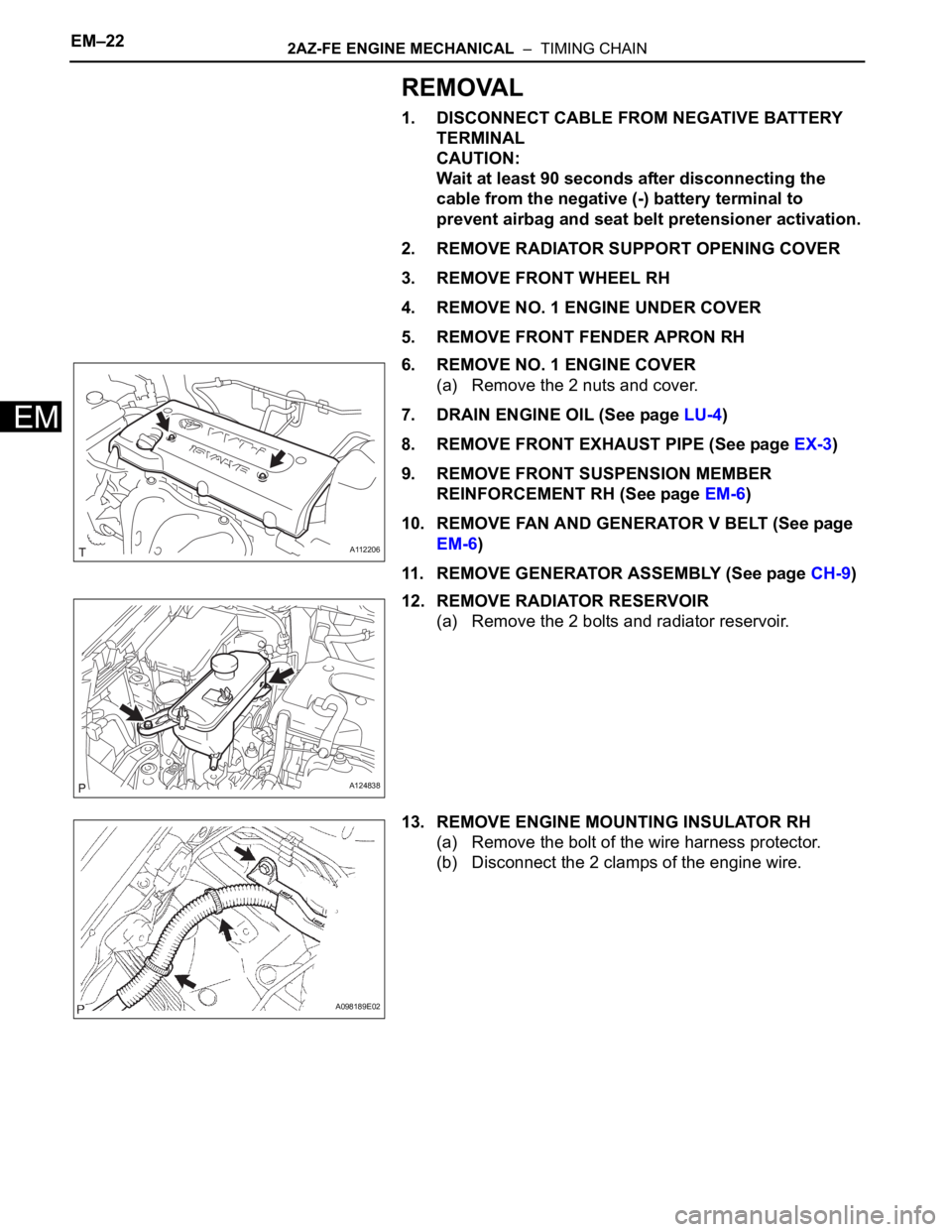
REMOVAL
1. DISCONNECT CABLE FROM NEGATIVE BATTERY
TERMINAL
CAUTION:
Wait at least 90 seconds after disconnecting the
cable from the negative (-) battery terminal to
prevent airbag and seat belt pretensioner activation.
2. REMOVE RADIATOR SUPPORT OPENING COVER
3. REMOVE FRONT WHEEL RH
4. REMOVE NO. 1 ENGINE UNDER COVER
5. REMOVE FRONT FENDER APRON RH
6. REMOVE NO. 1 ENGINE COVER
(a) Remove the 2 nuts and cover.
7. DRAIN ENGINE OIL (See page LU-4)
8. REMOVE FRONT EXHAUST PIPE (See page EX-3)
9. REMOVE FRONT SUSPENSION MEMBER
REINFORCEMENT RH (See page EM-6)
10. REMOVE FAN AND GENERATOR V BELT (See page
EM-6)
11. REMOVE GENERATOR ASSEMBLY (See page CH-9)
12. REMOVE RADIATOR RESERVOIR
(a) Remove the 2 bolts and radiator reservoir.
13. REMOVE ENGINE MOUNTING INSULATOR RH
(a) Remove the bolt of the wire harness protector.
(b) Disconnect the 2 clamps of the engine wire.
A112206
A124838
A098189E02
Page 583 of 2000
EM–262AZ-FE ENGINE MECHANICAL – TIMING CHAIN
EM
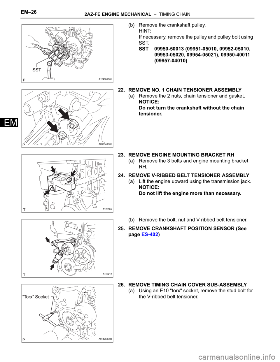
(b) Remove the crankshaft pulley.
HINT:
If necessary, remove the pulley and pulley bolt using
SST.
SST 09950-50013 (09951-05010, 09952-05010,
09953-05020, 09954-05021), 09950-40011
(09957-04010)
22. REMOVE NO. 1 CHAIN TENSIONER ASSEMBLY
(a) Remove the 2 nuts, chain tensioner and gasket.
NOTICE:
Do not turn the crankshaft without the chain
tensioner.
23. REMOVE ENGINE MOUNTING BRACKET RH
(a) Remove the 3 bolts and engine mounting bracket
RH.
24. REMOVE V-RIBBED BELT TENSIONER ASSEMBLY
(a) Lift the engine upward using the transmission jack.
NOTICE:
Do not lift the engine more than necessary.
(b) Remove the bolt, nut and V-ribbed belt tensioner.
25. REMOVE CRANKSHAFT POSITION SENSOR (See
page ES-402)
26. REMOVE TIMING CHAIN COVER SUB-ASSEMBLY
(a) Using an E10 "torx" socket, remove the stud bolt for
the V-ribbed belt tensioner.
A124860E01
A098348E01
A128165
A112212
A014253E03
Page 594 of 2000
2AZ-FE ENGINE MECHANICAL – TIMING CHAINEM–37
EM
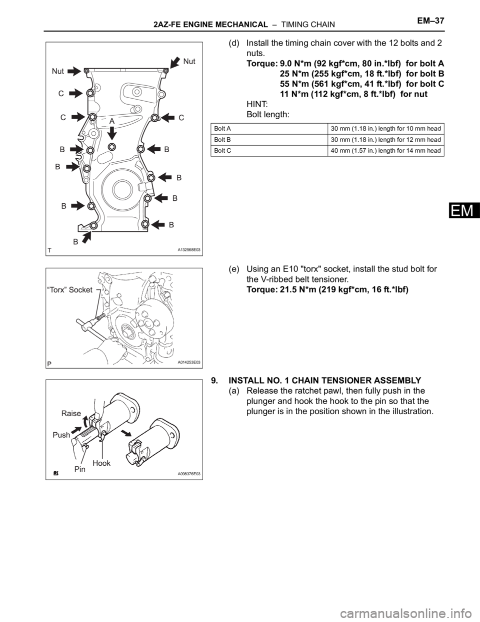
(d) Install the timing chain cover with the 12 bolts and 2
nuts.
Torque: 9.0 N*m (92 kgf*cm, 80 in.*lbf) for bolt A
25 N*m (255 kgf*cm, 18 ft.*lbf) for bolt B
55 N*m (561 kgf*cm, 41 ft.*lbf) for bolt C
11 N*m (112 kgf*cm, 8 ft.*lbf) for nut
HINT:
Bolt length:
(e) Using an E10 "torx" socket, install the stud bolt for
the V-ribbed belt tensioner.
Torque: 21.5 N*m (219 kgf*cm, 16 ft.*lbf)
9. INSTALL NO. 1 CHAIN TENSIONER ASSEMBLY
(a) Release the ratchet pawl, then fully push in the
plunger and hook the hook to the pin so that the
plunger is in the position shown in the illustration.
A132568E03
Bolt A 30 mm (1.18 in.) length for 10 mm head
Bolt B 30 mm (1.18 in.) length for 12 mm head
Bolt C 40 mm (1.57 in.) length for 14 mm head
A014253E03
A098376E03
Page 595 of 2000
EM–382AZ-FE ENGINE MECHANICAL – TIMING CHAIN
EM
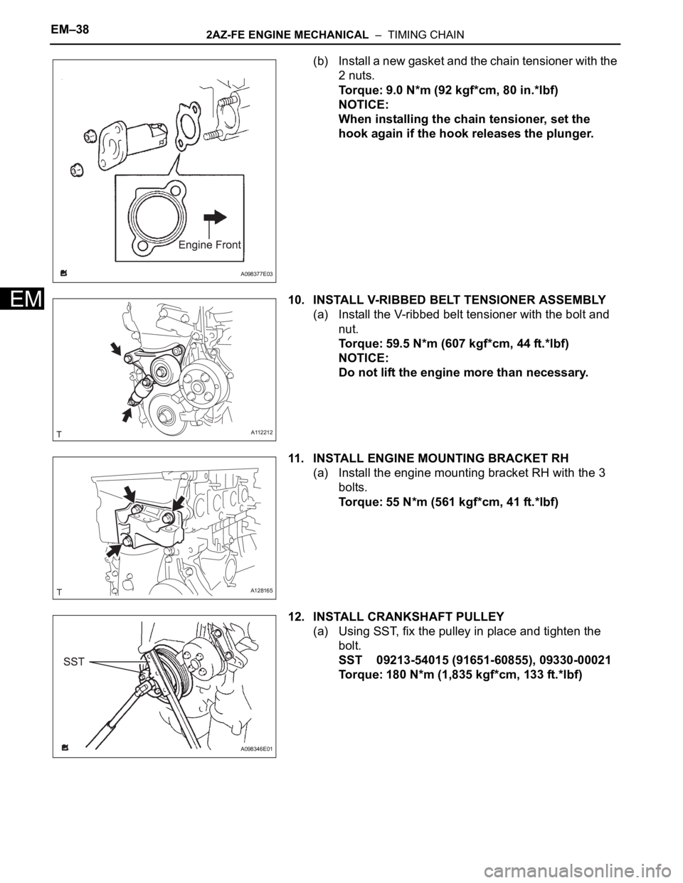
(b) Install a new gasket and the chain tensioner with the
2 nuts.
Torque: 9.0 N*m (92 kgf*cm, 80 in.*lbf)
NOTICE:
When installing the chain tensioner, set the
hook again if the hook releases the plunger.
10. INSTALL V-RIBBED BELT TENSIONER ASSEMBLY
(a) Install the V-ribbed belt tensioner with the bolt and
nut.
Torque: 59.5 N*m (607 kgf*cm, 44 ft.*lbf)
NOTICE:
Do not lift the engine more than necessary.
11. INSTALL ENGINE MOUNTING BRACKET RH
(a) Install the engine mounting bracket RH with the 3
bolts.
Torque: 55 N*m (561 kgf*cm, 41 ft.*lbf)
12. INSTALL CRANKSHAFT PULLEY
(a) Using SST, fix the pulley in place and tighten the
bolt.
SST 09213-54015 (91651-60855), 09330-00021
Torque: 180 N*m (1,835 kgf*cm, 133 ft.*lbf)
A098377E03
A112212
A128165
A098346E01
Page 599 of 2000
EM–422AZ-FE ENGINE MECHANICAL – TIMING CHAIN
EM
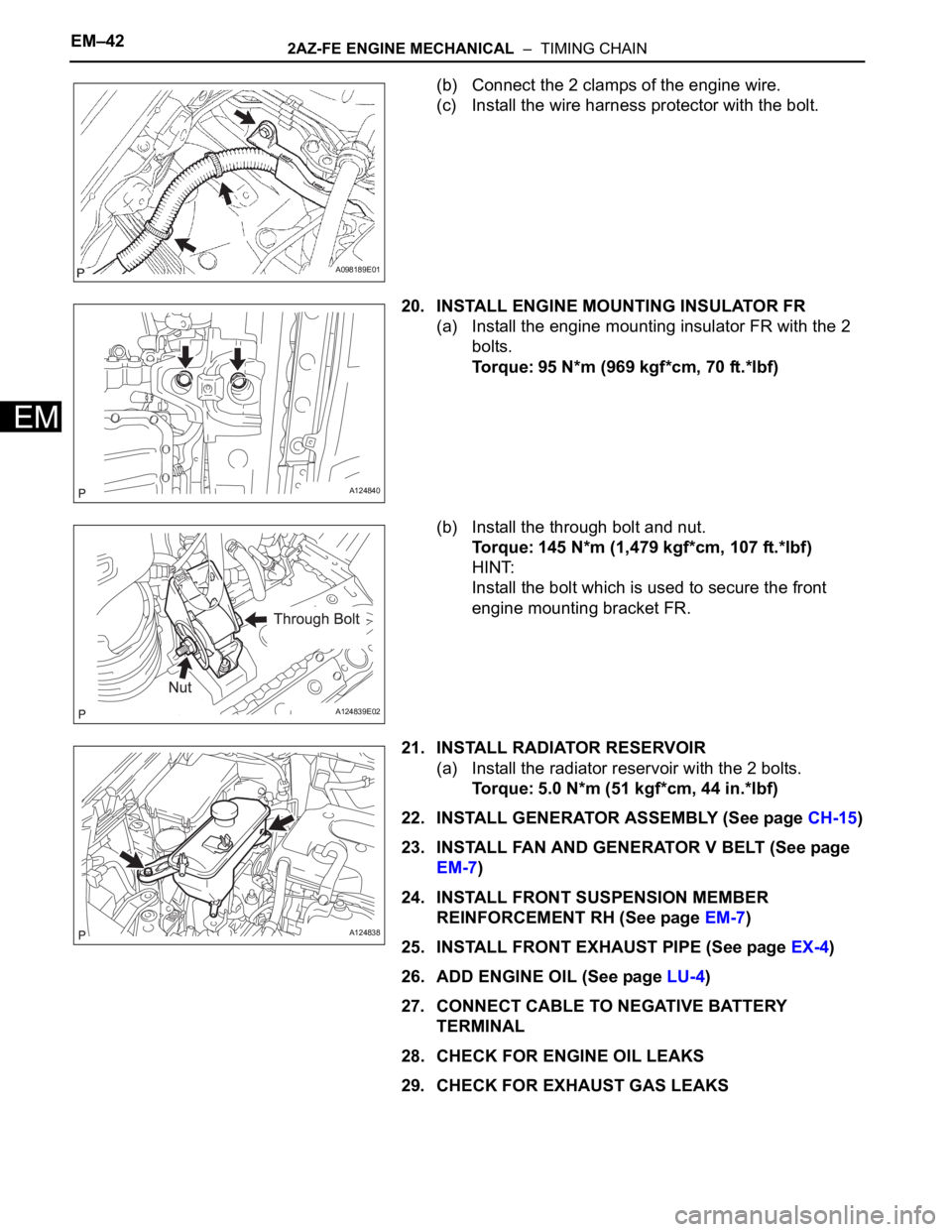
(b) Connect the 2 clamps of the engine wire.
(c) Install the wire harness protector with the bolt.
20. INSTALL ENGINE MOUNTING INSULATOR FR
(a) Install the engine mounting insulator FR with the 2
bolts.
Torque: 95 N*m (969 kgf*cm, 70 ft.*lbf)
(b) Install the through bolt and nut.
Torque: 145 N*m (1,479 kgf*cm, 107 ft.*lbf)
HINT:
Install the bolt which is used to secure the front
engine mounting bracket FR.
21. INSTALL RADIATOR RESERVOIR
(a) Install the radiator reservoir with the 2 bolts.
Torque: 5.0 N*m (51 kgf*cm, 44 in.*lbf)
22. INSTALL GENERATOR ASSEMBLY (See page CH-15)
23. INSTALL FAN AND GENERATOR V BELT (See page
EM-7)
24. INSTALL FRONT SUSPENSION MEMBER
REINFORCEMENT RH (See page EM-7)
25. INSTALL FRONT EXHAUST PIPE (See page EX-4)
26. ADD ENGINE OIL (See page LU-4)
27. CONNECT CABLE TO NEGATIVE BATTERY
TERMINAL
28. CHECK FOR ENGINE OIL LEAKS
29. CHECK FOR EXHAUST GAS LEAKS
A098189E01
A124840
A124839E02
A124838
Page 603 of 2000
2AZ-FE ENGINE MECHANICAL – CYLINDER HEADEM–59
EM
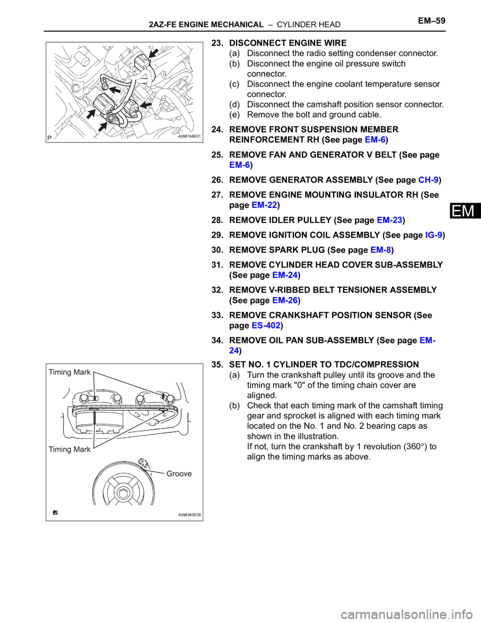
23. DISCONNECT ENGINE WIRE
(a) Disconnect the radio setting condenser connector.
(b) Disconnect the engine oil pressure switch
connector.
(c) Disconnect the engine coolant temperature sensor
connector.
(d) Disconnect the camshaft position sensor connector.
(e) Remove the bolt and ground cable.
24. REMOVE FRONT SUSPENSION MEMBER
REINFORCEMENT RH (See page EM-6)
25. REMOVE FAN AND GENERATOR V BELT (See page
EM-6)
26. REMOVE GENERATOR ASSEMBLY (See page CH-9)
27. REMOVE ENGINE MOUNTING INSULATOR RH (See
page EM-22)
28. REMOVE IDLER PULLEY (See page EM-23)
29. REMOVE IGNITION COIL ASSEMBLY (See page IG-9)
30. REMOVE SPARK PLUG (See page EM-8)
31. REMOVE CYLINDER HEAD COVER SUB-ASSEMBLY
(See page EM-24)
32. REMOVE V-RIBBED BELT TENSIONER ASSEMBLY
(See page EM-26)
33. REMOVE CRANKSHAFT POSITION SENSOR (See
page ES-402)
34. REMOVE OIL PAN SUB-ASSEMBLY (See page EM-
24)
35. SET NO. 1 CYLINDER TO TDC/COMPRESSION
(a) Turn the crankshaft pulley until its groove and the
timing mark "0" of the timing chain cover are
aligned.
(b) Check that each timing mark of the camshaft timing
gear and sprocket is aligned with each timing mark
located on the No. 1 and No. 2 bearing caps as
shown in the illustration.
If not, turn the crankshaft by 1 revolution (360
) to
align the timing marks as above.
A098748E01
A098345E09
Page 629 of 2000
2AZ-FE ENGINE MECHANICAL – CYLINDER HEADEM–85
EM
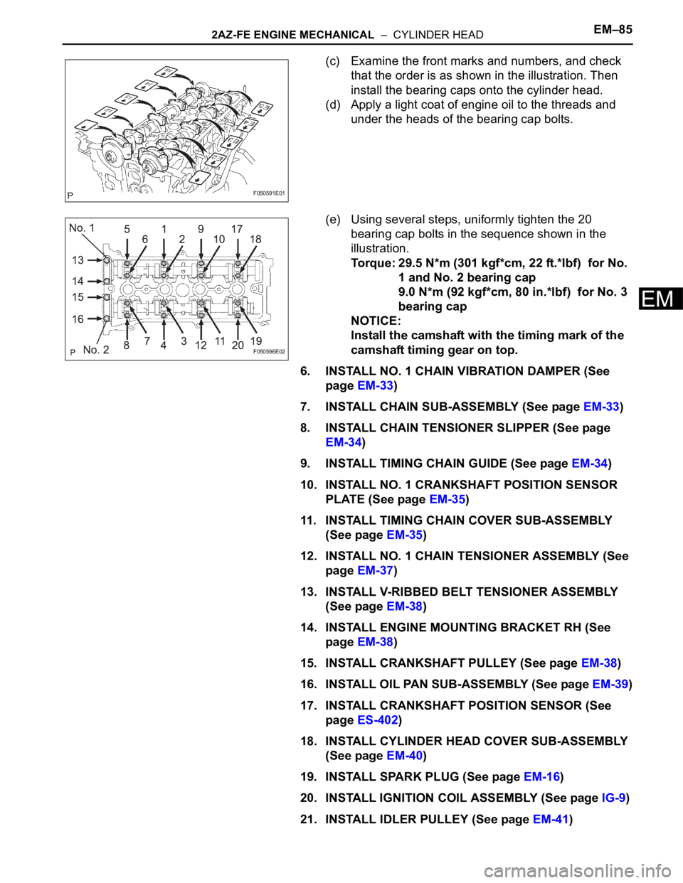
(c) Examine the front marks and numbers, and check
that the order is as shown in the illustration. Then
install the bearing caps onto the cylinder head.
(d) Apply a light coat of engine oil to the threads and
under the heads of the bearing cap bolts.
(e) Using several steps, uniformly tighten the 20
bearing cap bolts in the sequence shown in the
illustration.
Torque: 29.5 N*m (301 kgf*cm, 22 ft.*lbf) for No.
1 and No. 2 bearing cap
9.0 N*m (92 kgf*cm, 80 in.*lbf) for No. 3
bearing cap
NOTICE:
Install the camshaft with the timing mark of the
camshaft timing gear on top.
6. INSTALL NO. 1 CHAIN VIBRATION DAMPER (See
page EM-33)
7. INSTALL CHAIN SUB-ASSEMBLY (See page EM-33)
8. INSTALL CHAIN TENSIONER SLIPPER (See page
EM-34)
9. INSTALL TIMING CHAIN GUIDE (See page EM-34)
10. INSTALL NO. 1 CRANKSHAFT POSITION SENSOR
PLATE (See page EM-35)
11. INSTALL TIMING CHAIN COVER SUB-ASSEMBLY
(See page EM-35)
12. INSTALL NO. 1 CHAIN TENSIONER ASSEMBLY (See
page EM-37)
13. INSTALL V-RIBBED BELT TENSIONER ASSEMBLY
(See page EM-38)
14. INSTALL ENGINE MOUNTING BRACKET RH (See
page EM-38)
15. INSTALL CRANKSHAFT PULLEY (See page EM-38)
16. INSTALL OIL PAN SUB-ASSEMBLY (See page EM-39)
17. INSTALL CRANKSHAFT POSITION SENSOR (See
page ES-402)
18. INSTALL CYLINDER HEAD COVER SUB-ASSEMBLY
(See page EM-40)
19. INSTALL SPARK PLUG (See page EM-16)
20. INSTALL IGNITION COIL ASSEMBLY (See page IG-9)
21. INSTALL IDLER PULLEY (See page EM-41)
F050591E01
F050596E02