clock TOYOTA RAV4 2021 (in English) User Guide
[x] Cancel search | Manufacturer: TOYOTA, Model Year: 2021, Model line: RAV4, Model: TOYOTA RAV4 2021Pages: 748, PDF Size: 30.79 MB
Page 516 of 748
5166-1. Using the air conditioning system and defogger
6-1.Using the air conditioning system and defogger
*: If equipped
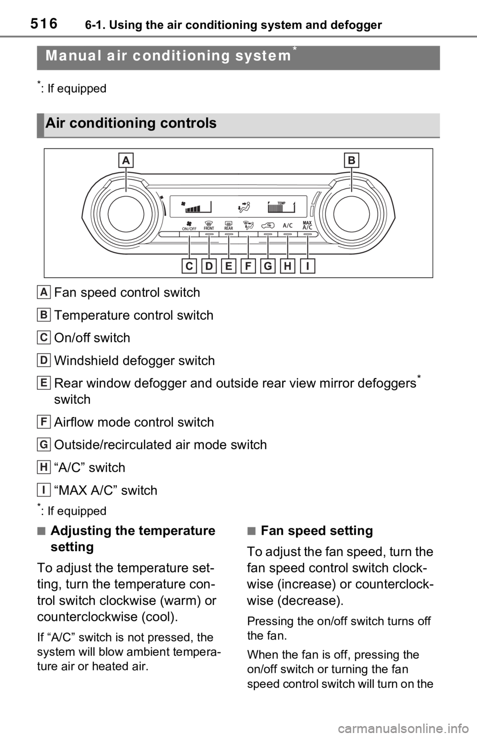
Fan speed control switch
Temperature control switch
On/off switch
Windshield defogger switch
Rear window defogger and outside rear view mirror defoggers
*
switch
Airflow mode control switch
Outside/recirculated air mode switch
“A/C” switch
“MAX A/C” switch
*: If equipped
■Adjusting the temperature
setting
To adjust the temperature set-
ting, turn the temperature con-
trol switch clockwise (warm) or
counterclockwise (cool).
If “A/C” switch is not pressed, the
system will blow a mbient tempera-
ture air or heated air.
■Fan speed setting
To adjust the fan speed, turn the
fan speed control switch clock-
wise (increase) or counterclock-
wise (decrease).
Pressing the on/off switch turns off
the fan.
When the fan is off, pressing the
on/off switch or turning the fan
speed control switch will turn on the
Manual air condi tioning system*
Air conditioning controls
A
B
C
D
E
F
G
H
I
Page 522 of 748
5226-1. Using the air conditioning system and defogger
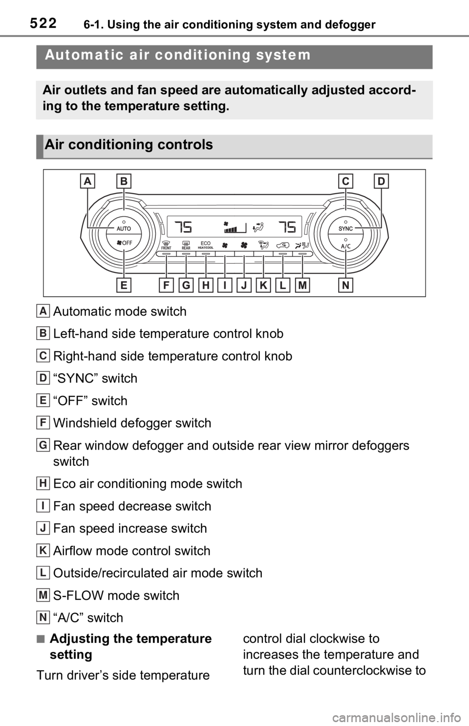
Automatic mode switch
Left-hand side temperature control knob
Right-hand side temperature control knob
“SYNC” switch
“OFF” switch
Windshield defogger switch
Rear window defogger and outside rear view mirror defoggers
switch
Eco air conditioning mode switch
Fan speed decrease switch
Fan speed increase switch
Airflow mode control switch
Outside/recirculated air mode switch
S-FLOW mode switch
“A/C” switch
■Adjusting the temperature
setting
Turn driver’s side temperature control dial clockwise to
increases the temperature and
turn the dial counterclockwise to
Automatic air co
nditioning system
Air outlets and fan speed are automatically adjusted accord-
ing to the temperature setting.
Air conditioning controls
A
B
C
D
E
F
G
H
I
J
K
L
M
N
Page 583 of 748
5837-3. Do-it-yourself maintenance
7
Maintenance and care
■Checking the engine oil
1 Park the vehicle on level
ground. After warming up the
engine and turning off the
engine, wait more than 5
minutes for the oil to drain
back into the bottom of the
engine.
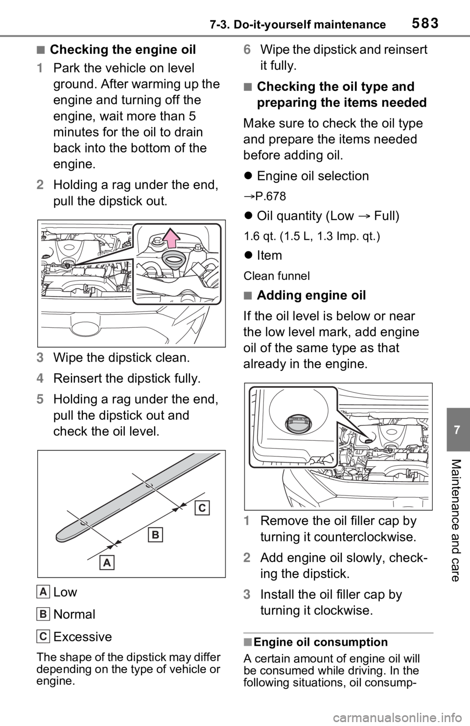
2 Holding a rag under the end,
pull the dipstick out.
3 Wipe the dipstick clean.
4 Reinsert the dipstick fully.
5 Holding a rag under the end,
pull the dipstick out and
check the oil level.
Low
Normal
Excessive
The shape of the dipstick may differ
depending on the type of vehicle or
engine.
6Wipe the dipstick and reinsert
it fully.
■Checking the oil type and
preparing the items needed
Make sure to check the oil type
and prepare the items needed
before adding oil.
Engine oil selection
P.678
Oil quantity (Low Full)
1.6 qt. (1.5 L, 1.3 Imp. qt.)
Item
Clean funnel
■Adding engine oil
If the oil level is below or near
the low level mark, add engine
oil of the same type as that
already in the engine.
1 Remove the oil filler cap by
turning it counterclockwise.
2 Add engine oil slowly, check-
ing the dipstick.
3 Install the oil filler cap by
turning it clockwise.
■Engine oil consumption
A certain amount of engine oil will
be consumed while driving. In the
following situatio ns, oil consump-
A
B
C
Page 620 of 748
6207-3. Do-it-yourself maintenance
High mounted stoplight
License plate lights
Outer foot lights (if equipped)
■LED lights
The lights other than the following
lights each consist of a number of
LEDs. If any of the LEDs burn out,
take your vehicle to your Toyota
dealer to have the light replaced.
●Front turn signal lights
●Parking lights
●Front side marker lights
●Fog lights (if equipped)
●Rear turn signal lights
●Back-up lights
■Condensation build-up on the
inside of the lens
Temporary condensation build-up
on the inside of the light lens does
not indicate a malfunction. Contact
your Toyota dealer for more infor-
mation in the following situations:
●Large drops of water have built up
on the inside of the lens.
●Water has built up inside the light.
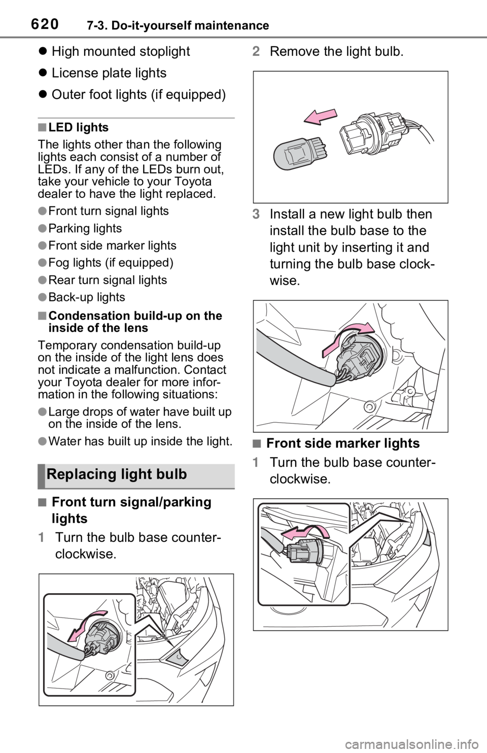
■Front turn signal/parking
lights
1 Turn the bulb base counter-
clockwise. 2
Remove the light bulb.
3 Install a new light bulb then
install the bulb base to the
light unit by inserting it and
turning the bulb base clock-
wise.
■Front side marker lights
1 Turn the bulb base counter-
clockwise.
Replacing light bulb
Page 621 of 748
6217-3. Do-it-yourself maintenance
7
Maintenance and care
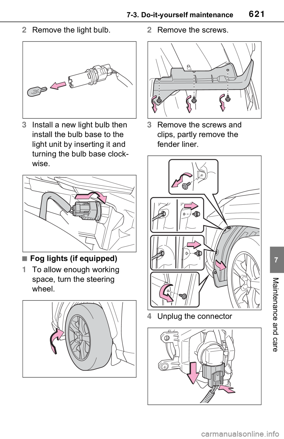
2Remove the light bulb.
3 Install a new light bulb then
install the bulb base to the
light unit by inserting it and
turning the bulb base clock-
wise.
■Fog lights (if equipped)
1 To allow enough working
space, turn the steering
wheel. 2
Remove the screws.
3 Remove the screws and
clips, partly remove the
fender liner.
4 Unplug the connector
Page 622 of 748
6227-3. Do-it-yourself maintenance
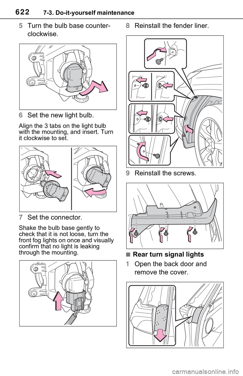
5Turn the bulb base counter-
clockwise.
6 Set the new light bulb.
Align the 3 tabs on the light bulb
with the mounting, and insert. Turn
it clockwise to set.
7 Set the connector.
Shake the bulb base gently to
check that it is not loose, turn the
front fog lights on once and visually
confirm that no light is leaking
through the mounting.
8Reinstall the fender liner.
9 Reinstall the screws.
■Rear turn signal lights
1 Open the back door and
remove the cover.
Page 623 of 748
6237-3. Do-it-yourself maintenance
7
Maintenance and care
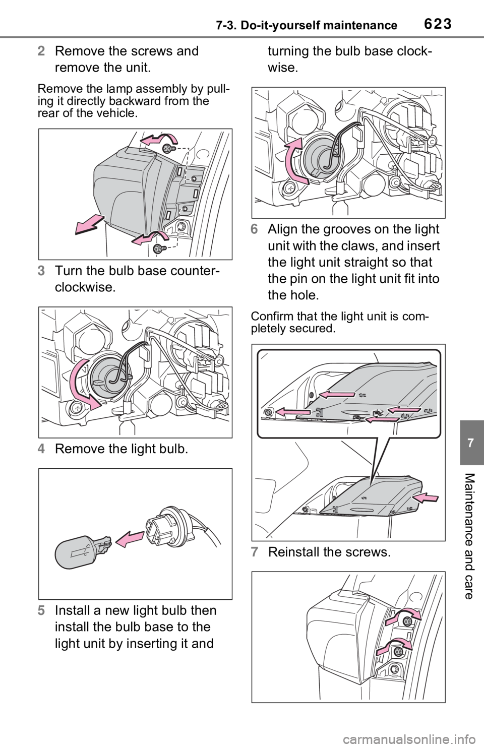
2Remove the screws and
remove the unit.
Remove the lamp assembly by pull-
ing it directly backward from the
rear of the vehicle.
3Turn the bulb base counter-
clockwise.
4 Remove the light bulb.
5 Install a new light bulb then
install the bulb base to the
light unit by inserting it and turning the bulb base clock-
wise.
6 Align the grooves on the light
unit with the claws, and insert
the light unit straight so that
the pin on the light unit fit into
the hole.
Confirm that the light unit is com-
pletely secured.
7Reinstall the screws.
Page 624 of 748
6247-3. Do-it-yourself maintenance
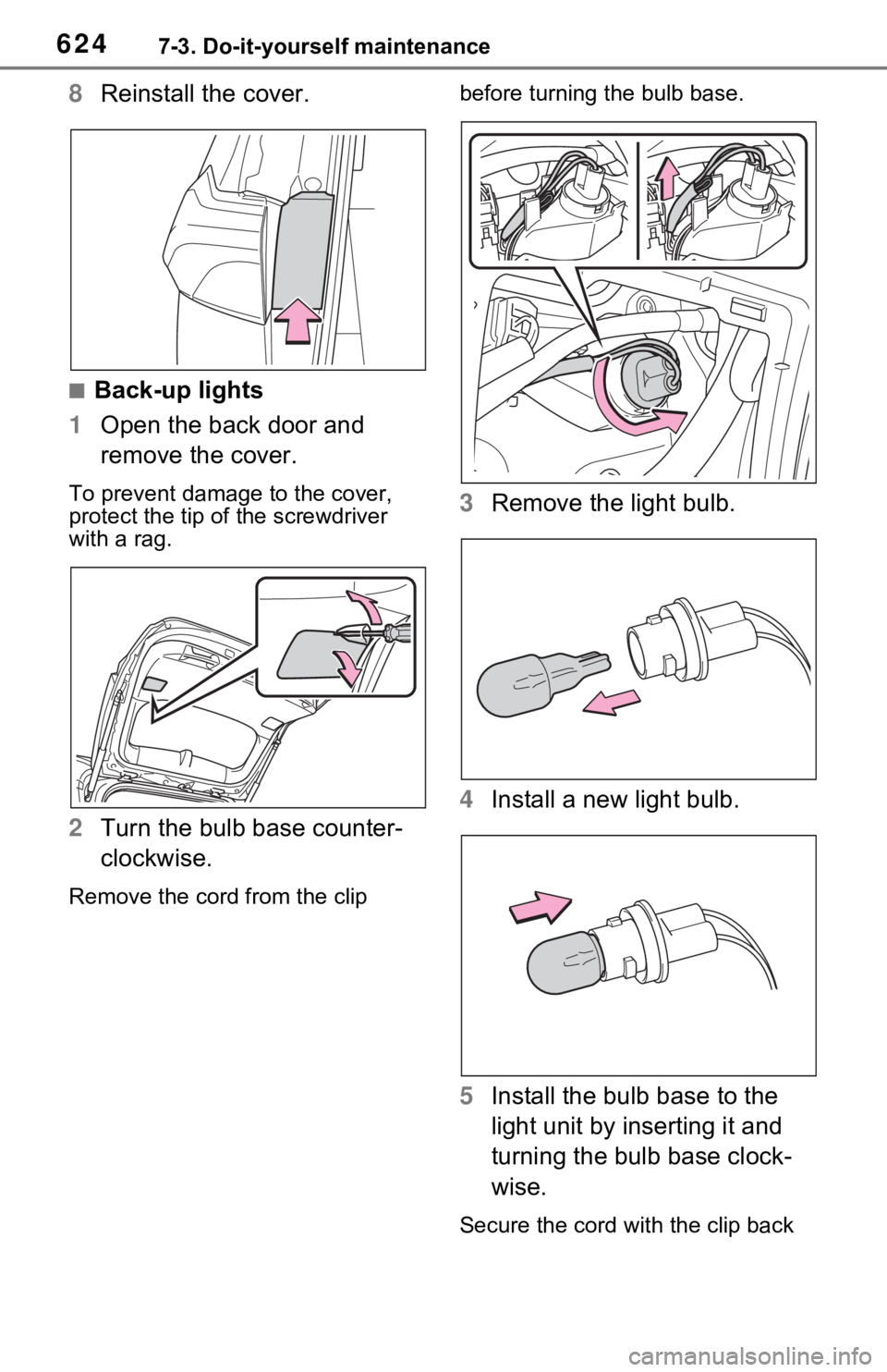
8Reinstall the cover.
■Back-up lights
1 Open the back door and
remove the cover.
To prevent damag e to the cover,
protect the tip of the screwdriver
with a rag.
2 Turn the bulb base counter-
clockwise.
Remove the cord from the clip before turning the bulb base.
3
Remove the light bulb.
4 Install a new light bulb.
5 Install the bulb base to the
light unit by inserting it and
turning the bulb base clock-
wise.
Secure the cord wit h the clip back
Page 731 of 748
Alphabetical Index731
control ............................ 84, 88
BSM (Blind Spot Monitor) ...... 264 Blind Spot Monitor function .. 268
Rear Cross Traffic Alert function........................................... 270
C
Care Aluminum wheels ................. 566
Exterior ................................. 566
Interior .................................. 569
Seat belts ............................. 569
Cargo capacity ............... 177, 180
Cargo hooks ........................... 539
Chains ..................................... 373
Child-protectors ..................... 114
Child restraint s ystem ............. 50
Fixed with a LATCH system ... 59
Fixed with a seat belt ............. 54
Front passenger occupant clas- sification system ................... 43
Points to remember ................ 50
Riding with children ................ 49
Types of child restraint system installation met hod ............... 52
Using an anchor bracket ........ 61
Child safety ............................... 49 Airbag precautions ................. 38
Back door precautions ......... 115
Battery precautions ...... 588, 669
Child restraint system............. 52
Heated steering wheel and seat
heater precautions ............. 529
How your child should wear the seat belt................................ 30
Moon roof precau tions ......... 162
Panoramic moon roof precau- tions.................................... 166
Power window lock switch.... 160
Power window precautions .. 159
Rear door child-protectors.... 114
Seat belt extender precautions .............................................30
Seat belt precautions..............29
Seat heater precautions .......529
Cleaning ..........................566, 569 Aluminum wheels .................566
Exterior .................................566
Interior ..................................569
Radar sensor ........................227
Seat belts .............................569
Clock ....................................84, 88
Coat hooks ..............................556
Condenser ............. ..................585
Connected Service s ...............501
Console box ............................536
Consumption screen ................99
Coolant Checking ..............................584
Preparing and checking before winter ..................................371
Warning light ........................639
Cooling system .......................584 Engine overheating ..............670
Cruise control (Dynamic radar
cruise control with full-speed
range).....................................253
Cup holders.............................536
Current fuel consumption........99
Current fuel economy ..............91
Curtain shield airbags ..............33
Customizable featu res ...........700
D
Daytime running light system212
Replacing light bulbs ............619
DCM .................502, 504, 505, 508
Deck board ..............................539
Defogger Outside rear view mirrors ...517, 524
Rear window.................517, 524
Windshield ....................517, 524
Differential ...............................681
Page 736 of 748
736Alphabetical Index
Warning messages .............. 249
Language (multi-information dis- play) ................................. 96, 701
LATCH anchors ........................ 59
Lever Auxiliary catch lever ............. 579
Hood lock release lever........ 579
Shift lever ............................. 201
Turn signal lever................... 204
Wiper lever ................... 218, 221
License plate lights Light switch .......................... 211
Replacing light bulbs ............ 619
Light bulbs Replacing ............................. 619
Wattage ................................ 682
Lights Automatic High Beam system........................................... 214
Fog light switch .................... 217
Front interior lights ............... 532
Headlight switch ................... 211
Interior lights......................... 532
Personal lights...................... 533
Rear interior light .................. 533
Replacing light bulbs ............ 619
Turn signal lever................... 204
Vanity lights .......................... 544
Wattage ................................ 682
Linking multi-information display and the system ..................... 393
Lock steering column ............ 197
LTA (Lane Tracing Assist) ..... 240 Operation ............................. 240
Warning messages .............. 249
Luggage compartment light................................ 118, 121Wattage ................................ 682
Luggage cover........ ................ 541
M
Maintenance Do-it-yourself maintenance ..577
General maintenance ...........573
Maintenance data .................676
Maintenance requirements ...572
Malfunction indicator lamp ....639
Manual air conditioning system ...............................................516Air conditioning filter .............608
Menu icons ................................90
Menu screen............................381 Menu screen operation.........381
Meter Clock ................................82, 85
Indicators ................................76
Instrument panel light control.............................84, 88
Meter control switches............90
Meters ..............................82, 85
Multi-information display.........89
Settings ..........................94, 701
Units ...............................96, 701
Warning lights.......................638
Warning messages .........98, 649
Meter control switches.............90
Microphone ........... ..................474
Mirrors Digital Rear-view Mirror ........147
Inside rear view mirror ..........145
Outside rear view mirror defog-gers ............................517, 524
Outside rear view mirrors .....156
Vanity mirrors ..... ..................544
Mobile Assistant .....................469 Connectable devices and avail-able functions .....................469
Mobile Assistant operation ...469
Moon roof Door lock linked moon roof oper-ation....................................161
Jam protection function ........161
Operation..............................161
Warning message . ...............162