navigation system TOYOTA RAV4 2022 Owners Manual
[x] Cancel search | Manufacturer: TOYOTA, Model Year: 2022, Model line: RAV4, Model: TOYOTA RAV4 2022Pages: 748, PDF Size: 22.93 MB
Page 20 of 748
20Pictorial index
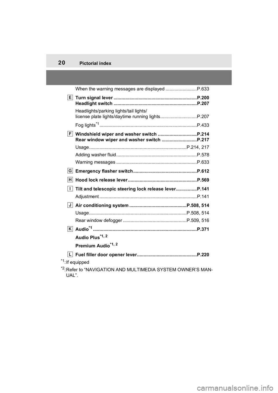
When the warning messages are displayed ........................P.633
Turn signal lever ................................................................P.200
Headlight switch ................................................................P.207
Headlights/parking lights/tail lights/
license plate lights/daytime running lights .................... ........P.207
Fog lights
*1............................................................... ............P.433
Windshield wiper and washer switch ..............................P.214
Rear window wiper and washer switch ...........................P.217
Usage.......................................................... .................P.214, 217
Adding washer fluid ..............................................................P.578
Warning messages ..............................................................P.633
Emergency flasher switch ....................................... ..........P.612
Hood lock release lever ........................................ .............P.569
Tilt and telescopic steering lock release lever ................P.141
Adjustment ..................................................... ......................P.141
Air conditioning system ............................. ...............P.508, 514
Usage.......................................................... .................P.508, 514
Rear window defogger ........................................... ......P.509, 516
Audio
*1............................................................... .................P.371
Audio Plus
*1, 2
Premium Audio*1, 2
Fuel filler door opener lever .................................. ............P.220
*1: If equipped
*2: Refer to “NAVIGATION AND MULTIMEDIA SYSTEM OWNER’S MAN-
UAL”.
E
F
G
H
I
J
K
L
Page 22 of 748
22Pictorial index
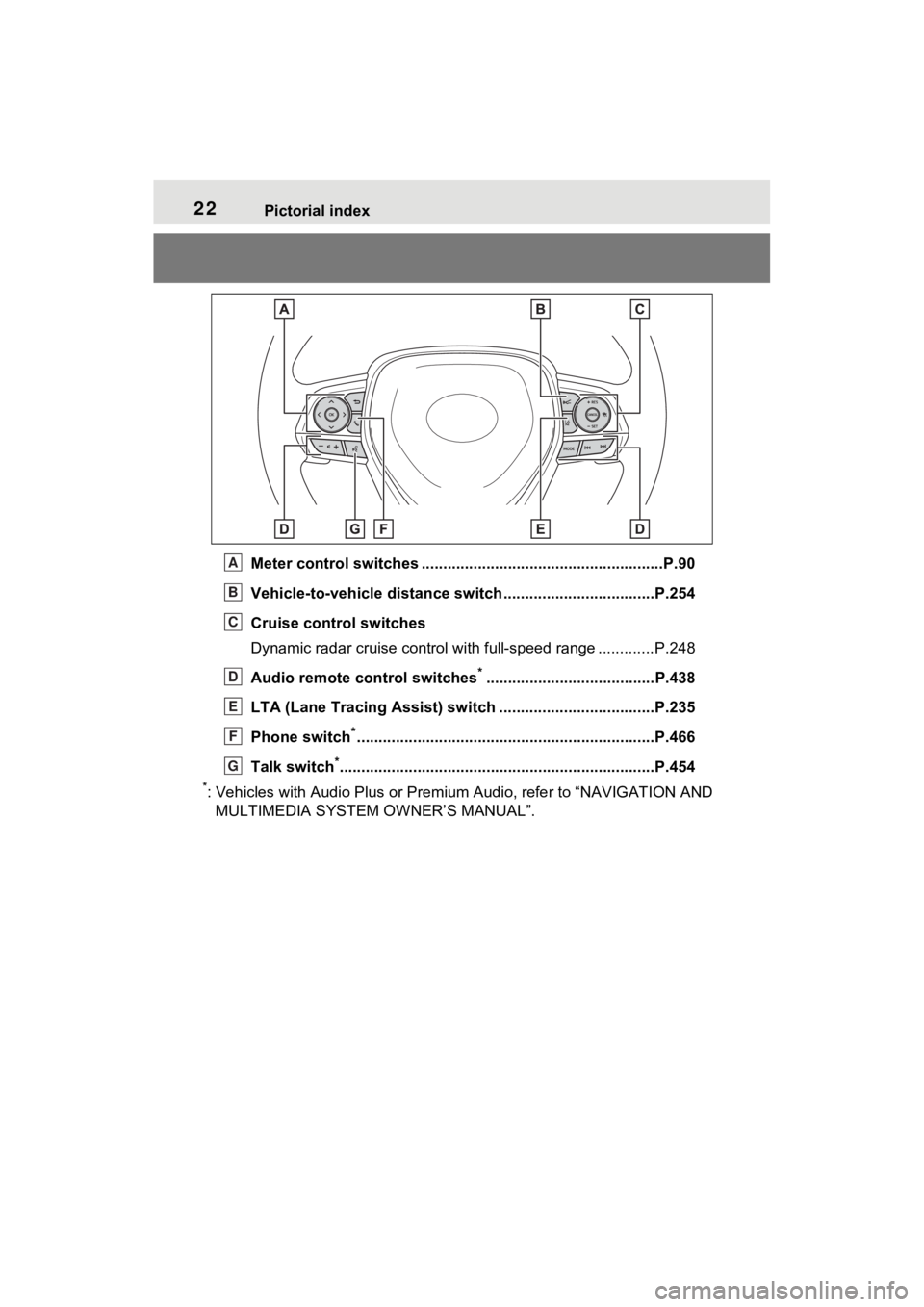
Meter control switches ........................................................P.90
Vehicle-to-vehicle distance switch ...................................P.254
Cruise control switches
Dynamic radar cruise control with full-speed range ............. P.248
Audio remote control switches
*.......................................P.438
LTA (Lane Tracing Assist) sw itch ....................................P.235
Phone switch
*............................................................... ......P.466
Talk switch
*............................................................... ..........P.454
*: Vehicles with Audio Plus or Premium Audio, refer to “NAVIGATION AND
MULTIMEDIA SYSTEM O WNER’S MANUAL”.
A
B
C
D
E
F
G
Page 84 of 748
842-1. Instrument cluster
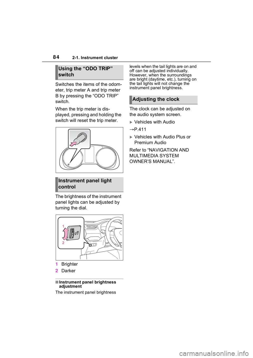
Switches the items of the odom-
eter, trip meter A and trip meter
B by pressing the “ODO TRIP”
switch.
When the trip meter is dis-
played, pressing and holding the
switch will reset the trip meter.
The brightness of the instrument
panel lights can be adjusted by
turning the dial.
1Brighter
2 Darker
■Instrument panel brightness
adjustment
The instrument panel brightness levels when the tail lights are on and
off can be adjusted individually.
However, when the surroundings
are bright (daytime, etc.), turning on
the tail lights will not change the
instrument panel brightness.
The clock can be adjusted on
the audio system screen.
Vehicles with Audio
P.411
Vehicles with Audio Plus or
Premium Audio
Refer to “NAVIGATION AND
MULTIMEDIA SYSTEM
OWNER’S MANUAL”.
Using the “ODO TRIP”
switch
Instrument panel light
control
Adjusting the clock
Page 88 of 748
882-1. Instrument cluster
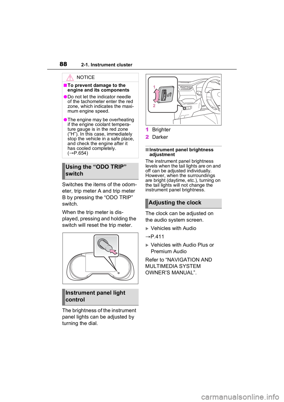
Switches the items of the odom-
eter, trip meter A and trip meter
B by pressing the “ODO TRIP”
switch.
When the trip meter is dis-
played, pressing and holding the
switch will reset the trip meter.
The brightness of the instrument
panel lights can be adjusted by
turning the dial.1
Brighter
2 Darker
■Instrument panel brightness
adjustment
The instrument panel brightness
levels when the tail lights are on and
off can be adjusted individually.
However, when the surroundings
are bright (daytime, etc.), turning on
the tail lights will not change the
instrument panel brightness.
The clock can be adjusted on
the audio system screen.
Vehicles with Audio
P.411
Vehicles with Audio Plus or
Premium Audio
Refer to “NAVIGATION AND
MULTIMEDIA SYSTEM
OWNER’S MANUAL”.
NOTICE
■To prevent damage to the
engine and its components
●Do not let the i ndicator needle
of the tachomete r enter the red
zone, which indicates the maxi-
mum engine speed.
●The engine may be overheating
if the engine coolant tempera-
ture gauge is in the red zone
(“H”). In this case, immediately
stop the vehicle in a safe place,
and check the engine after it
has cooled completely.
( P.654)
Using the “ODO TRIP”
switch
Instrument panel light
control
Adjusting the clock
Page 93 of 748
932-1. Instrument cluster
2
Vehicle status information and indicators
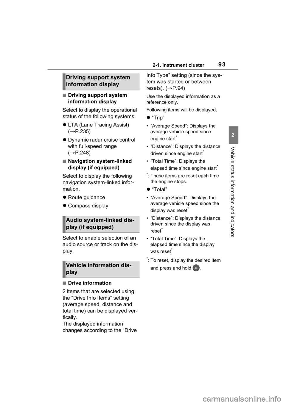
■Driving support system
information display
Select to display the operational
status of the following systems:
LTA (Lane Tracing Assist)
( P.235)
Dynamic radar cruise control
with full-speed range
( P.248)
■Navigation system-linked
display (if equipped)
Select to display the following
navigation system-linked infor-
mation.
Route guidance
Compass display
Select to enable selection of an
audio source or track on the dis-
play.
■Drive information
2 items that are selected using
the “Drive Info Items” setting
(average speed, distance and
total time) can be displayed ver-
tically.
The displayed information
changes according to the “Drive Info Type” setting (since the sys-
tem was started or between
resets). (
P.94)
Use the displayed information as a
reference only.
Following items will be displayed.
“Trip”
• “Average Speed”: Displays the
average vehicle speed since
engine start
*
• “Distance”: Displ ays the distance
driven since engine start
*
• “Total Time”: Displays the elapsed time since engine start
*
*
: These items are r eset each time
the engine stops.
“Total”
• “Average Speed”: Displays the
average vehicle speed since the
display was reset
*
• “Distance”: Displ ays the distance
driven since the display was
reset
*
• “Total Time”: Displays the elapsed time since the display
was reset
*
*
: To reset, display the desired item and press and hold .
Driving support system
information display
Audio system-linked dis-
play (if equipped)
Vehicle information dis-
play
Page 97 of 748
972-1. Instrument cluster
2
Vehicle status information and indicators
play settings)
Select to change the display on
Fuel Economy (P.91).
(Audio settings) (if
equipped)
Select to enable/disable
screen.
(Vehicle information dis-
play settings)
• “Display Contents”
Select to enable/disable the AWD
system display ( P.94). (AWD
models)
• “Drive Info Type”
Select to change the drive informa-
tion type display between trip and
total. ( P.93).
• “Drive Info Items”
Select to set the items on the upper
and lower side of the drive informa-
tion screen from three items, aver-
age speed, distance and total time.
“Pop-Up Display”
Select to enable/d isable the follow-
ing pop-up displays, which may
appear in some situations.
• Intersection guidance display of the navigation system-linked sys-
tem (if equipped)
• Incoming call display of the hands-free phone system (if
equipped)
• Audio operation (if equipped)
• Volume operation (if equipped)
• Voice control (if equipped)
• Stop & Start system duration (if equipped) • Stop & Start system status (if
equipped)
“MID OFF”
A blank screen is displayed
“Default Settings”
Select to reset the meter display
settings.
■Suspension of the settings dis-
play
●In the following situations, opera-
tion of the settings display will be
temporarily suspended.
• When a warning message appears on the multi-information
display
• When the vehicle begins to move
●Settings for functions not
equipped to the vehicle are not
displayed.
●When a function is turned off, the
related settings for that function
are not selectable.
WARNING
■Cautions during setting up
the display
As the engine needs to be run-
ning during setting up the display,
ensure that the vehicle is parked
in a place with adequate ventila-
tion. In a closed area such as a
garage, exhaust gases including
harmful carbon monoxide (CO)
may collect and enter the vehicle.
This may lead to death or a seri-
ous health hazard.
NOTICE
■During setting up the display
To prevent battery discharge,
ensure that the engine is running
while setting up the display fea-
tures.
Page 247 of 748
2474-5. Using the driving support systems
4
Driving
nizes a do not enter sign and
determines that your vehicle
has entered a no-entry area,
the displayed sign will flash
and a buzzer will sound.
Depending on the situation, a
notification function may not
operate properly.
■Setting procedure
P.94
■Automatic turn-off of RSA sign
display
In the following si tuations, a dis-
played speed limit sign and/or do
not enter sign will stop being dis-
played automatically:
●No sign has been recognized for a
certain distance.
●The road changes due to a left or
right turn, etc.
In the following si tuations, stop and
yield signs will stop being displayed
automatically:
●The system determines that your
vehicle has passed the sign.
●The road changes due to a left or
right turn, etc.
■Conditions in which the func-
tion may not operate or detect
correctly
In the following situations, RSA
does not operate normally and may
not recognize signs, display the
incorrect sign, etc. However, this
does not indicate a malfunction.
●The front camera is misaligned
due to a strong impact being
applied to the sensor, etc.
●D i r t , s n o w , s t i c k e r s , e t c . a r e o n t h e
windshield near the front camera.
●In inclement weather such as
heavy rain, fog, snow or sand
storms.
●Light from an oncoming vehicle, the sun, etc. ente
rs the front cam-
era.
●The sign is dirty, faded, tilted or
bent.
●The contrast of electronic sign is
low.
●All or part of the sign is hidden by
the leaves of a tree, a pole, etc.
●The sign is only visible to the front
camera for a short amount of time.
●The driving scene (turning, lane
change, etc.) is judged incorrectly.
●If a sign not appropriate for the
currently traveled lane, but the
sign exists directly after a freeway
branches, or in an adjacent lane
just before merging.
●Stickers are attached to the rear
of the preceding vehicle.
●A sign resembling a system com-
patible sign is recognized.
●Side road speed signs may be
detected and displayed (if posi-
tioned in sight of the front camera)
while the vehicle i s traveling on
the main road.
●Roundabout exit road speed signs
may be detected and displayed (if
positioned in si ght of the front
camera) while t raveling on a
roundabout.
●The front of the vehicle is raised or
lowered due to the carried load.
●The surrounding brightness is not
sufficient or changes suddenly.
●When a sign inte nded for trucks,
etc. is recognized.
●The speed information displayed
on the meter and on the naviga-
tion system may be different due
to the navigation system using
map data.
■Speed limit sign display
If the engine switch was last turned
off while a speed limit sign was dis-
played on the multi-information dis-
play, the same sign displays again
Page 266 of 748
2664-5. Using the driving support systems
tion/RCTA function are turned on
• When towing a trailer
●Instances of the BSM function
unnecessarily detecting a vehicle
and/or object may increase in the
following situations:
• When the sensor is misaligned
due to a strong impact to the sen-
sor or its surrounding area
• When the distanc e between your
vehicle and a guar drail, wall, etc.
that enters the detection area is
short
• When driving up and down con-
secutive steep inclines, such as
hills, dips in the road, etc.
• When vehicle lanes are narrow, or
when driving on the edge of a
lane, and a vehicle traveling in a
lane other than the adjacent lanes
enters the detection area
• When driving on roads with sharp bends, consecutive curves, or
uneven surfaces
• When the tires are slipping or spinning
• When the distanc e between your
vehicle and a following vehicle is
short
• When an accessory (such as a bicycle carrier) is installed to the
rear of the vehicle
• When the vehicle throws up water or snow behind.
■Operation of the RCTA
function
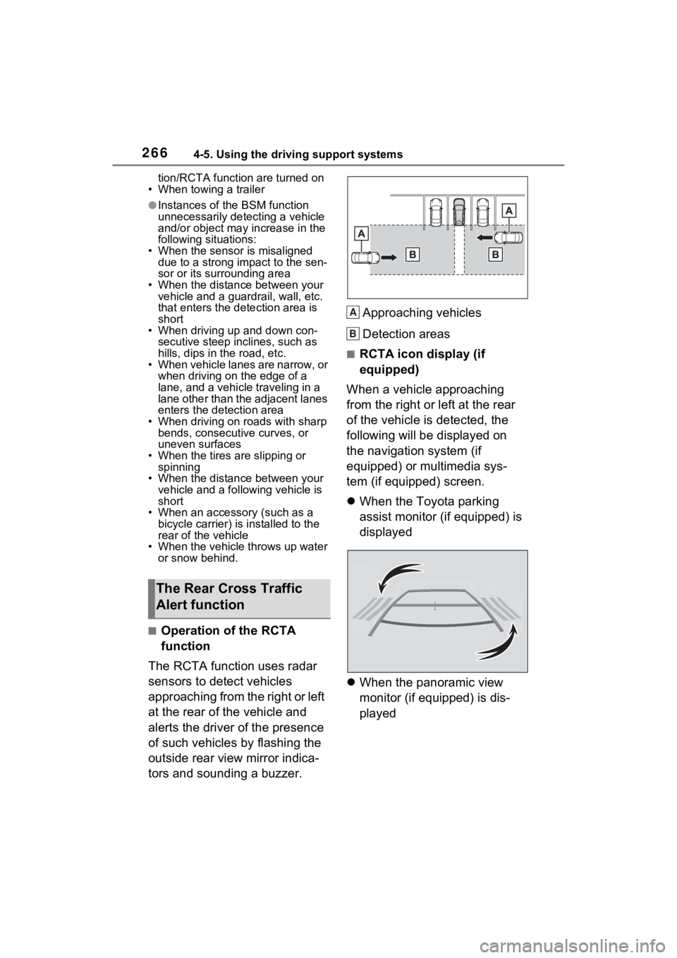
The RCTA function uses radar
sensors to detect vehicles
approaching from the right or left
at the rear of the vehicle and
alerts the driver of the presence
of such vehicles by flashing the
outside rear view mirror indica-
tors and sounding a buzzer. Approaching vehicles
Detection areas
■RCTA icon display (if
equipped)
When a vehicle approaching
from the right or left at the rear
of the vehicle is detected, the
following will be displayed on
the navigation system (if
equipped) or multimedia sys-
tem (if equipped) screen.
When the Toyota parking
assist monitor (if equipped) is
displayed
When the panoramic view
monitor (if equipped) is dis-
played
The Rear Cross Traffic
Alert function
A
B
Page 270 of 748
2704-5. Using the driving support systems
*: If equipped
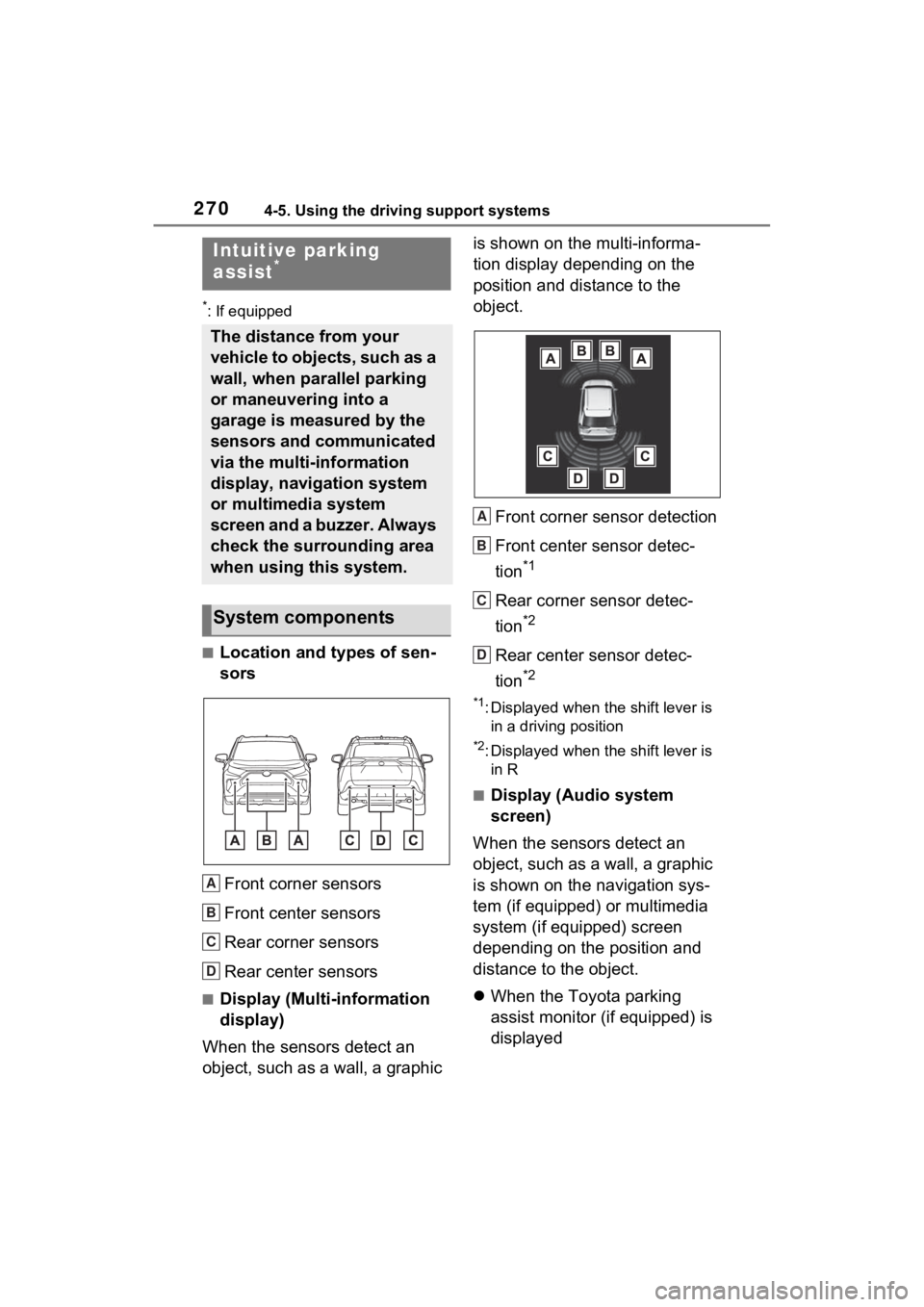
■Location and types of sen-
sorsFront corner sensors
Front center sensors
Rear corner sensors
Rear center sensors
■Display (Multi-information
display)
When the sensors detect an
object, such as a wall, a graphic is shown on the multi-informa-
tion display depending on the
position and distance to the
object.
Front corner sensor detection
Front center sensor detec-
tion
*1
Rear corner sensor detec-
tion
*2
Rear center sensor detec-
tion
*2
*1: Displayed when the shift lever is in a driving position
*2: Displayed when the shift lever is in R
■Display (Audio system
screen)
When the sensors detect an
object, such as a wall, a graphic
is shown on the navigation sys-
tem (if equipped) or multimedia
system (if equipped) screen
depending on the position and
distance to the object.
When the Toyota parking
assist monitor (if equipped) is
displayed
Intuitive parking
assist*
The distance from your
vehicle to objects, such as a
wall, when parallel parking
or maneuvering into a
garage is measured by the
sensors and communicated
via the multi-information
display, navigation system
or multimedia system
screen and a buzzer. Always
check the surrounding area
when using this system.
System components
A
B
C
D
A
B
C
D
Page 276 of 748
2764-5. Using the driving support systems
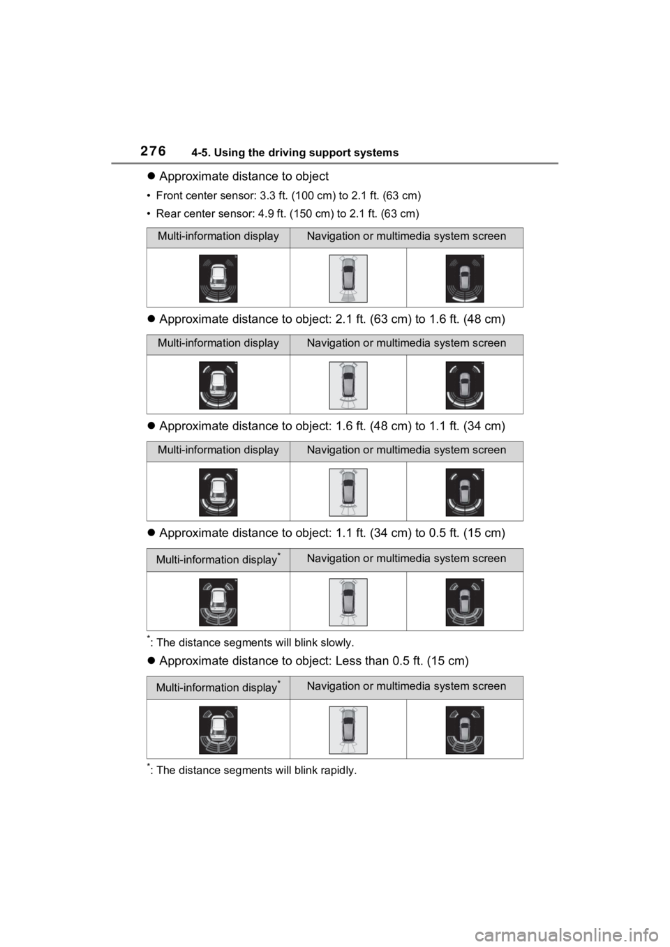
Approximate distance to object
• Front center sensor: 3.3 ft . (100 cm) to 2.1 ft. (63 cm)
• Rear center sensor : 4.9 ft. (150 cm) to 2.1 ft. (63 cm)
Approximate distance to object: 2.1 ft. (63 cm) to 1.6 ft. (48 cm)
Approximate distance to object: 1.6 ft. (48 cm) to 1.1 ft. (34 cm)
Approximate distance to object: 1.1 ft. (34 cm) to 0.5 ft. (15 cm)
*: The distance segments will blink slowly.
Approximate distance to object: Less than 0.5 ft. (15 cm)
*: The distance segments will blink rapidly.
Multi-information displayNavigation or multimedia system screen
Multi-information displayNavigation or multimedia system screen
Multi-information displayNavigation or multimedia system screen
Multi-information display*Navigation or multimedia system screen
Multi-information display*Navigation or multimedia system screen