ECU TOYOTA RAV4 2022 Manual Online
[x] Cancel search | Manufacturer: TOYOTA, Model Year: 2022, Model line: RAV4, Model: TOYOTA RAV4 2022Pages: 748, PDF Size: 22.93 MB
Page 619 of 748
6198-2. Steps to take in an emergency
8
When trouble arises
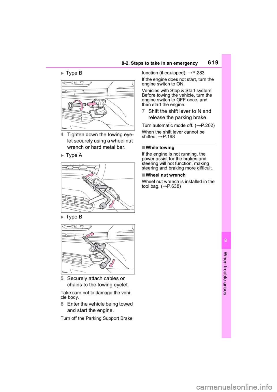
Type B
4 Tighten down the towing eye-
let securely using a wheel nut
wrench or hard metal bar.
Type A
Type B
5 Securely attach cables or
chains to the towing eyelet.
Take care not to damage the vehi-
cle body.
6Enter the vehicle being towed
and start the engine.
Turn off the Parkin g Support Brake function (if equipped):
P.283
If the engine does not start, turn the
engine switch to ON.
Vehicles with Stop & Start system:
Before towing the ve hicle, turn the
engine switch to OFF once, and
then start the engine.
7 Shift the shift lever to N and
release the parking brake.
Turn automatic mode off. ( P.202)
When the shift lever cannot be
shifted: P.198
■While towing
If the engine is not running, the
power assist for the brakes and
steering will not function, making
steering and braking more difficult.
■Wheel nut wrench
Wheel nut wrench is installed in the
tool bag. ( P.638)
Page 630 of 748

6308-2. Steps to take in an emergency
the warning light to flash and the
warning buzzer to sound even if a
passenger is not sitting in the
seat.
●If a cushion is placed on the seat,
the sensor may not detect a pas-
senger, and the warning light may
not operate properly.
■SRS warning light
This warning light system monitors
the airbag sensor assembly, front
impact sensors, side impact sensors
(front door), side impact sensors
(front), driver’s seat position sen-
sor, driver’s seat belt buckle switch,
front passenger occupant classifica-
tion system (ECU and sensors),
“AIR BAG ON” indicator light, “AIR
BAG OFF” indicator light, front pas-
senger’s seat belt buckle switch,
driver’s seat belt p retensioner, front
passenger’s seat be lt pretensioner
and force limiter, airbags, intercon-
necting wiring and power sources.
( P.36)
■If the malfunction indicator
lamp comes on while driving
First check the following:
●Is the fuel t ank empty?
If it is, fill the fuel tank immediately.
●Is the fuel tank cap loose?
If it is, tighten it securely.
The light will go o ff after several
driving trips.
If the light does not go off even after
several trips, contact your Toyota
dealer as soon as possible.
■Electric power steering system
warning light (warning buzzer)
When the battery charge becomes
insufficient or the voltage temporar-
ily drops, the electric power steering
system warning light may come on
and the warning buzzer may sound.
■When the tire pressure warning
light comes on ( vehicles with
tire pressure warning system)
Inspect the tires to check if a tire is
punctured.
If a tire is punctured: P.637
If none of the tires are punctured:
Turn the engine switch to OFF then
turn it to ON. Check if the tire pres-
sure warning light comes on or
blinks.
If the tire pressur e warning light
blinks for approximately 1 minute
then stays on
There may be a malfunction in the
tire pressure warning system. Have
the vehicle inspected by your
Toyota dealer immediately.
If the tire pressur e warning light
comes on
1 After the temperature of the tires
has lowered sufficiently, check
the inflation pressure of each tire
and adjust them to the specified
level.
2 If the warning light does not turn
off even after several minutes
have elapsed, check that the
inflation pressure of each tire is
at the specified level and perform
initialization. ( P.584)
■The tire pressure warning light
may come on due to natural
causes (vehicles with tire pres-
sure warning system)
The tire pressure warning light may
come on due to natural causes such
as natural air leaks and tire inflation
pressure changes caused by tem-
perature. In this ca se, adjusting the
tire inflation pressure will turn off the
warning ligh t (after a few minutes).
■When a tire is replaced with a
compact spare tire (vehicles
with tire pressure warning sys-
tem)
The compact spare tire is not
equipped with a tire pressure warn-
Page 640 of 748
6408-2. Steps to take in an emergency
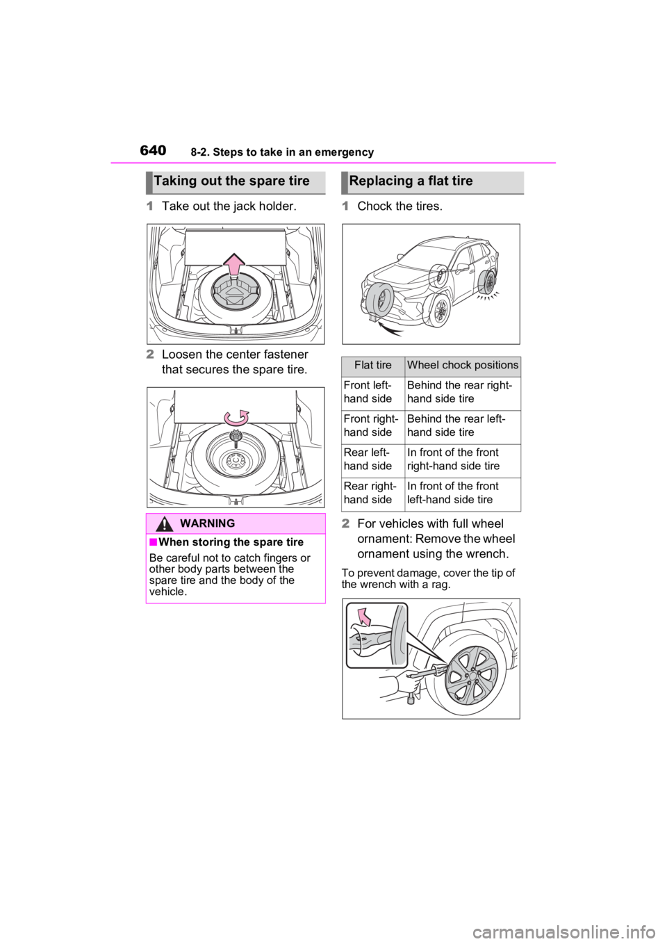
1Take out the jack holder.
2 Loosen the center fastener
that secures the spare tire. 1
Chock the tires.
2 For vehicles with full wheel
ornament: Remove the wheel
ornament using the wrench.
To prevent damage, cover the tip of
the wrench with a rag.
Taking out the spare tire
WARNING
■When storing the spare tire
Be careful not to catch fingers or
other body parts between the
spare tire and the body of the
vehicle.
Replacing a flat tire
Flat tireWheel chock positions
Front left-
hand sideBehind the rear right-
hand side tire
Front right-
hand sideBehind the rear left-
hand side tire
Rear left-
hand sideIn front of the front
right-hand side tire
Rear right-
hand sideIn front of the front
left-hand side tire
Page 645 of 748
6458-2. Steps to take in an emergency
8
When trouble arises
WARNING
●Avoid sudden acceleration,
abrupt steering, sudden brak-
ing and shifting operations that
cause sudden engine braking.
■When the compact spare tire
is attached
The vehicle speed may not be
correctly detecte d, and the follow-
ing systems may not operate cor-
rectly:
• ABS & Brake assist
• VSC/Trailer Sway Control
• TRAC
• Dynamic radar cruise control with full-speed range
• PCS (Pre-Collision System)
• EPS
• LTA (Lane Tracing Assist)
• Tire pressure warning system (if equipped)
• AHB (Automatic High Beam)
• BSM (Blind Spot Monitor) (if equipped)
• Downhill assist control system (if equipped)
• Rear view monitor system (if equipped)
• Panoramic view monitor (if equipped)
• Toyota parking assist monitor (if equipped)
• Intuitive parking assist (if equipped)
• Navigation system (if equipped)
Also, not only c an the following
systems not be ut ilized fully, but
they may actually negatively
affect the drive-train components:
• Dynamic Torque Control AWD system (if equipped)
• Dynamic Torque Vectoring AWD system (if equipped)
■Speed limit when using the
compact spare tire
Do not drive at speeds in excess
of 50 mph (80 km /h) when a com-
pact spare tire is installed on the
vehicle.
The compact spare tire is not
designed for driving at high
speeds. Failure to observe this
precaution may lead to an acci-
dent causing death or serious
injury.
■After using the tools and jack
Before driving, ma ke sure all the
tools and jack are securely in
place in their storage location to
reduce the possibility of personal
injury during a collision or sudden
braking.
NOTICE
■Be careful when driving over
bumps with the compact
spare tire installed on the
vehicle
The vehicle height may become
lower when drivi ng with the com-
pact spare tire compared to when
driving with standard tires. Be
careful when driving over uneven
road surfaces.
Page 652 of 748

6528-2. Steps to take in an emergency
■Starting the engine when the
battery is discharged
The engine cannot be started by
push-starting.
■To prevent battery discharge
●Turn off the headlights and the
audio system while the engine is
stopped.
(Vehicles with Stop & Start system:
Except when the engine is stopped
due to the Stop & Start system)
●Turn off any unnec essary electri-
cal components when the vehicle
is running at a low speed for an
extended period, such as in heavy
traffic.
■When the battery is removed or
discharged
●Information stor ed in the ECU is
cleared. When the battery is
depleted, have the vehicle
inspected at your Toyota dealer.
●Some systems may require initial-
ization. ( P.696)
■When removing the battery ter-
minals
When the battery terminals are
removed, the information stored in
the ECU is cleared . Before remov-
ing the battery terminals, contact
your Toyota dealer.
■Charging the battery
The electricity stor ed in the battery
will discharge gradu ally even when
the vehicle is not i n use, due to nat-
ural discharge and the draining
effects of certain electrical appli-
ances. If the vehicle is left for a long
time, the battery may discharge,
and the engine ma y be unable to
start. (The battery recharges auto-
matically during driving.)
■When recharging or replacing
the battery (vehicles without
smart key start system)
The engine may not start on the first
attempt after the battery has recharged but will start normally
after the second attempt. This is not
a malfunction.
■When recharging or replacing
the battery (vehicles with smart
key system)
●In some cases, it may not be pos-
sible to unlock the doors using the
smart key system when the bat-
tery is discharged. Use the wire-
less remote control or the
mechanical key to lock or unlock
the doors.
●The engine may not start on the
first attempt after
the battery has
recharged but will start normally
after the second attempt. This is
not a malfunction.
●The engine switch mode is memo-
rized by the vehicle. When the
battery is reconnected, the system
will return to the mode it was in
before the bat tery was dis-
charged. Before disconnecting the
battery, turn the engine switch to
OFF.
If you are unsure what mode the
engine switch wa s in before the
battery discharged, be especially
careful when reconnecting the
battery.
■When the battery is removed or
discharged (vehicles with Stop
& Start system)
The Stop & Start system may not
automatically stop the engine for up
to an hour.
■When replacing the battery
●Vehicles with Stop & Start system:
Use a genuine battery specifically
designed for use with the Stop &
Start system or a battery with equiv-
alent specifications to a genuine
battery. If an unsup ported battery is
used, Stop & Start system functions
may be restricted to protect the bat-
tery. Also, battery performance may
decrease and the engine may not
be able to restart. Contact your
Toyota dealer for details.
Page 653 of 748
6538-2. Steps to take in an emergency
8
When trouble arises
●Use a battery that conforms to
European regulations.
●Type A:
Use a battery that the case size is
same as the previous one (LN3), 20
hours rate capacity (20HR) is equiv-
alent (65Ah) or greater, and perfor-
mance rating (CCA) is equivalent
(603A) or greater.
Type B:
Use a battery that the case size is
same as the previous one (LN2), 20
hours rate capacity (20HR) is equiv-
alent (60Ah) or greater, and perfor-
mance rating (CCA) is equivalent
(360A) or greater.
Type C:
Use a battery that the case size is
same as the previous one (LN2), 20
hours rate capacity (20HR) is equiv-
alent (60Ah) or greater, and perfor-
mance rating (CCA) is equivalent
(563A) or greater.
• If the sizes differ, the battery can- not be properly secured.
• If the 20 hour rate capacity is low,
even if the time period where the
vehicle is not used is a short time,
the battery may discharge and
engine may not be able to start.
WARNING
■When removing the battery
terminals
Always remove the negative (-)
terminal first. If the positive (+) ter-
minal contacts any metal in the
surrounding area when the posi-
tive (+) terminal is removed, a
spark may occur, l eading to a fire
in addition to electrical shocks
and death or serious injury.
■Avoiding battery fires or
explosions
Observe the following precautions
to prevent accidentally igniting the
flammable gas that may be emit-
ted from the battery:
●Make sure each jumper cable is
connected to the correct termi-
nal and that it is not unintention-
ally in contact with any other
than the intended terminal.
●Do not allow the other end of
the jumper cable connected to
the “+” terminal to come into
contact with any other parts or
metal surfaces in the area, such
as brackets or unpainted metal.
●Do not allow the + and - clamps
of the jumper cables to come
into contact with each other.
●Do not smoke, use matches,
cigarette lighter s or allow open
flame near the battery.
■Battery precautions
The battery contains poisonous
and corrosive acidic electrolyte,
while related parts contain lead
and lead compounds. Observe
the following precautions when
handling the battery:
●When working with the battery,
always wear safety glasses and
take care not to allow any bat-
tery fluids (acid) to come into
contact with skin, clothing or the
vehicle body.
●Do not lean over the battery.
●In the event that battery fluid
comes into contact with the skin
or eyes, immediately wash the
affected area with water and
seek medical attention.
Place a wet sponge or cloth
over the affected area until
medical attention can be
received.
Page 683 of 748
6839-1. Specifications
9
Vehicle specifications
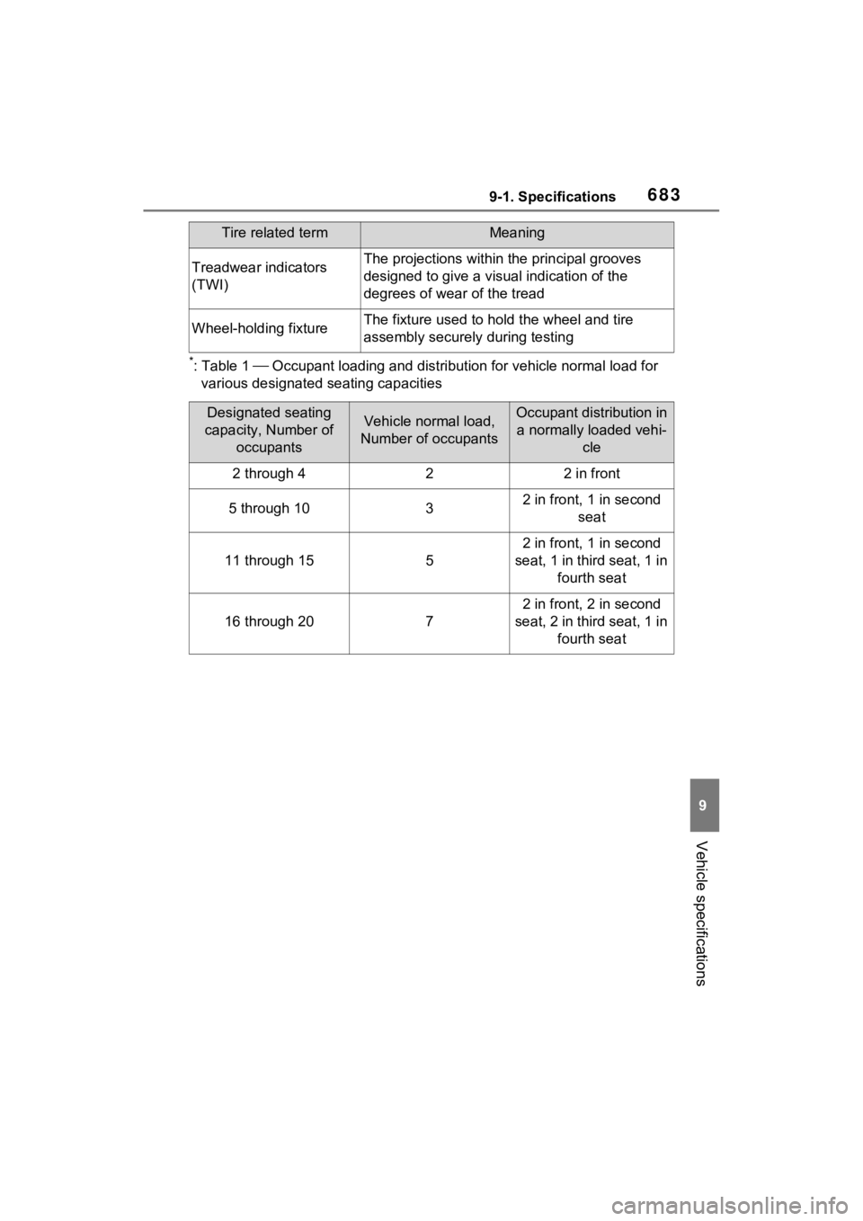
*:Table 1 Occupant loading and distribution for vehicle normal load for
various designated seating capacities
Treadwear indicators
(TWI)The projections within the principal grooves
designed to give a visual indication of the
degrees of wear of the tread
Wheel-holding fixtureThe fixture used to hold the wheel and tire
assembly securely during testing
Designated seating
capacity, Number of occupantsVehicle normal load,
Number of occupantsOccupant distribution in a normally loaded vehi- cle
2 through 422 in front
5 through 1032 in front, 1 in second
seat
11 through 155
2 in front, 1 in second
seat, 1 in third seat, 1 in fourth seat
16 through 207
2 in front, 2 in second
seat, 2 in third seat, 1 in fourth seat
Tire related termMeaning
Page 688 of 748
6889-2. Customization
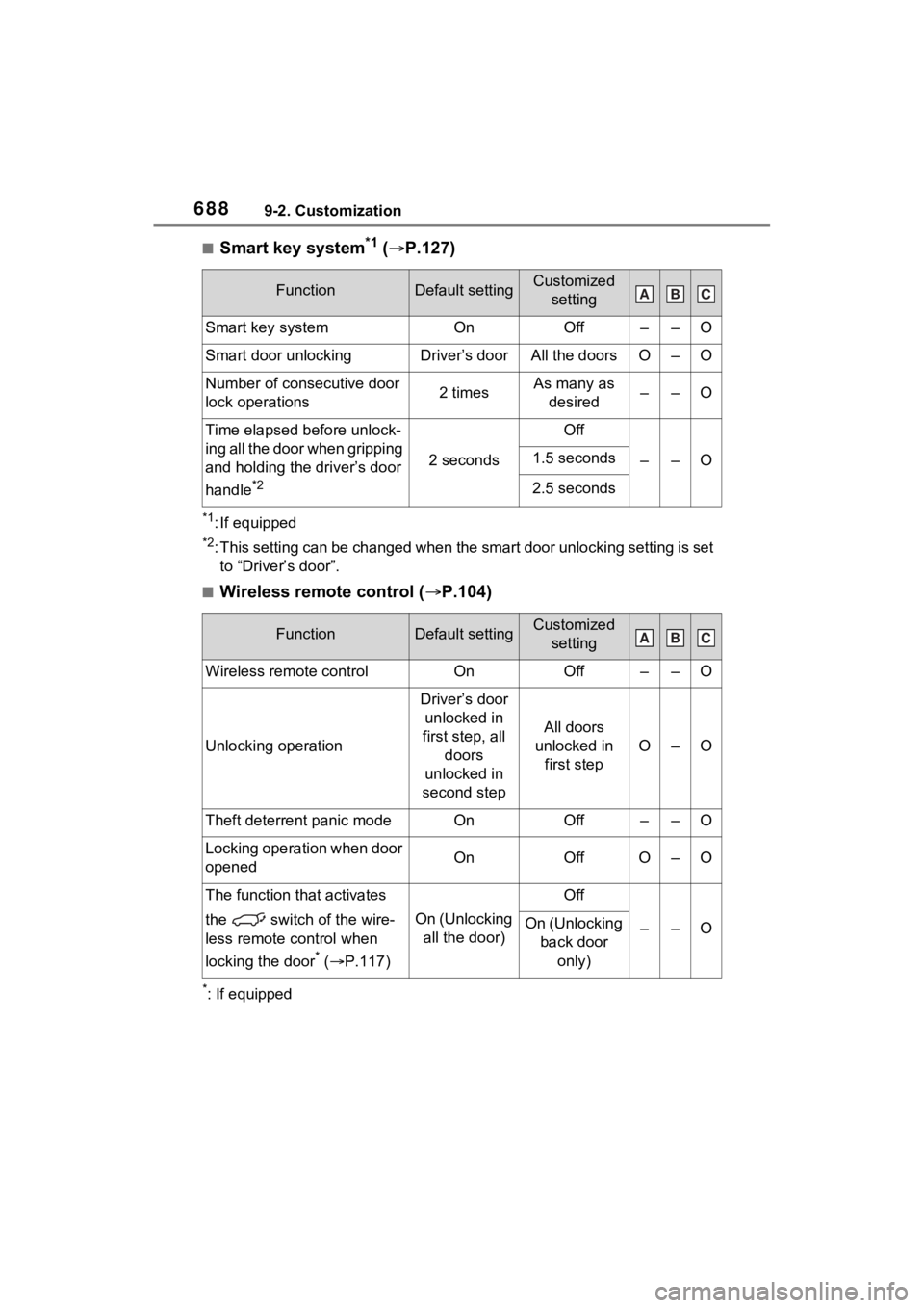
■Smart key system*1 ( P.127)
*1: If equipped
*2: This setting can be changed when the smart door unlocking sett ing is set
to “Driver’s door”.
■Wireless remote control ( P.104)
*: If equipped
FunctionDefault settingCustomized
setting
Smart key systemOnOff––O
Smart door unlockingDriver’s doorAll the doorsO–O
Number of consecutive door
lock operations2 timesAs many as desired––O
Time elapsed before unlock-
ing all the door when gripping
and holding the driver’s door
handle
*2
2 seconds
Off
––O1.5 seconds
2.5 seconds
FunctionDefault settingCustomized setting
Wireless remote controlOnOff––O
Unlocking operation
Driver’s door unlocked in
first step, all doors
unlocked in
second step
All doors
unlocked in first step
O–O
Theft deterrent panic modeOnOff––O
Locking operation when door
openedOnOffO–O
The function that activates
the switch of the wire-
less remote control when
locking the door
* ( P.117)
On (Unlocking
all the door)
Off
––OOn (Unlocking back door
only)
ABC
ABC
Page 699 of 748
69910-1. For owners
10
For owners
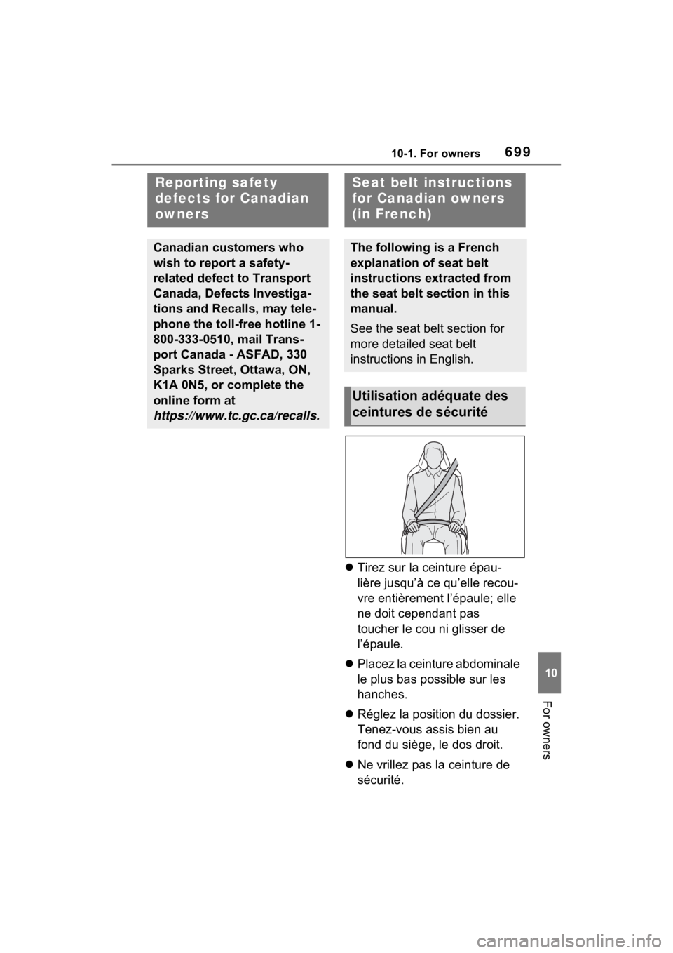
Tirez sur la ceinture épau-
lière jusqu’à ce qu’elle recou-
vre entièrement l’épaule; elle
ne doit cependant pas
toucher le cou ni glisser de
l’épaule.
Placez la ceinture abdominale
le plus bas possible sur les
hanches.
Réglez la position du dossier.
Tenez-vous assis bien au
fond du siège, le dos droit.
Ne vrillez pas la ceinture de
sécurité.
Reporting safety
defects for Canadian
owners
Canadian customers who
wish to report a safety-
related defect to Transport
Canada, Defects Investiga-
tions and Recalls, may tele-
phone the toll-free hotline 1-
800-333-0510, mail Trans-
port Canada - ASFAD, 330
Sparks Street, Ottawa, ON,
K1A 0N5, or complete the
online form at
https://www.tc.gc.ca/recalls.
Seat belt in structions
for Canadian owners
(in French)
The following is a French
explanation of seat belt
instructions extracted from
the seat belt section in this
manual.
See the seat belt section for
more detailed seat belt
instructions in English.
Utilisation adéquate des
ceintures de sécurité
Page 700 of 748
70010-1. For owners
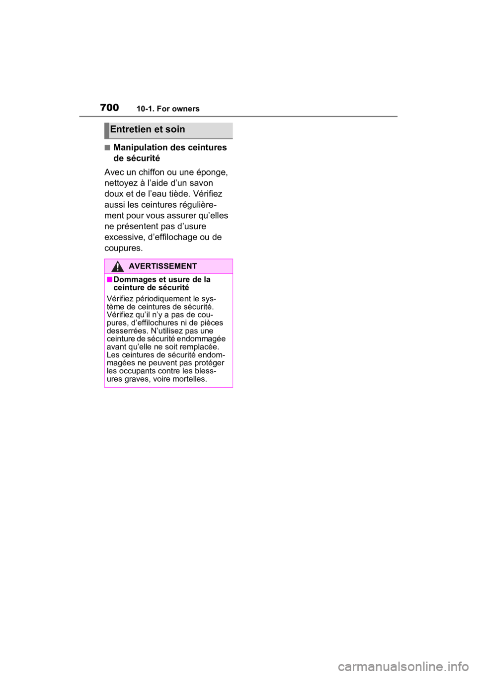
■Manipulation des ceintures
de sécurité
Avec un chiffon ou une éponge,
nettoyez à l’aide d’un savon
doux et de l’eau tiède. Vérifiez
aussi les ceintures régulière-
ment pour vous assurer qu’elles
ne présentent pas d’usure
excessive, d’effilochage ou de
coupures.
Entretien et soin
AVERTISSEMENT
■Dommages et usure de la
ceinture de sécurité
Vérifiez périodiquement le sys-
tème de ceintures de sécurité.
Vérifiez qu’il n’y a pas de cou-
pures, d’effilochures ni de pièces
desserrées. N’utilisez pas une
ceinture de sécurité endommagée
avant qu’elle ne soit remplacée.
Les ceintures de sécurité endom-
magées ne peuvent pas protéger
les occupants contre les bless-
ures graves, voire mortelles.