display TOYOTA RAV4 HYBRID 2023 Owners Manual
[x] Cancel search | Manufacturer: TOYOTA, Model Year: 2023, Model line: RAV4 HYBRID, Model: TOYOTA RAV4 HYBRID 2023Pages: 586, PDF Size: 17.55 MB
Page 331 of 586

3294-5. Using the driving support systems
4
Driving
the systems will be automatically re-
enabled in the following situations:
●When the power switch is turned
off
●If only the TRAC system is turned
off, the TRAC will turn on when
vehicle speed increases
If both the TRAC and VSC sys-
tems are turned off, automatic re-
enabling will not oc cur when vehi-
cle speed increases.
■Operating conditions of Active
Cornering Assist
The system operates when the fol-
lowing occurs.
●TRAC/VSC can operate
●The driver is at tempting to accel-
erate while turning
●The system detects that the vehi-
cle is drifting to the outer side
●The brake pedal is released
■Reduced effectiveness of the
EPS system
The effectiveness of the EPS sys-
tem is reduced to prevent the sys-
tem from overheating when there is
frequent steering input over an
extended period of time. The steer-
ing wheel may feel heavy as a
result. Should this occur, refrain
from excessive steering input or
stop the vehicle and turn the hybrid
system off. The EPS system should
return to normal within 10 minutes.
■Secondary Collision Brake
operating conditions
The system operates when the SRS
airbag sensor de tects a collision
while the vehicle is in motion. How-
ever, the system does not operate
when the components are dam-
aged.
■Secondary Collision Brake
automatic cancellation
The system is automatically can-
celed in any of th e following situa-
tions.
●The vehicle speed is below 6 mph (10 km/h)
●A certain amount of time elapses
during operation
●The accelerator pedal is
depressed a large amount
■If a message about AWD is
shown on the multi-information
display (AWD models)
Perform the following actions.
●“AWD System Overheated
Switching to 2WD Mode”
AWD system is overheated. Stop
the vehicle in a safe place with the
hybrid system operating.
*
If the message disappears after a
while, there is no problem. If the
message remains, have the vehicle
inspected by your Toyota dealer
immediately.
●“AWD System Overheated 2WD
Mode Engaged”
AWD system has been temporarily
released and swit ched to front-
wheel drive due to overheating.
Stop the vehicle in a safe place with
the hybrid system operating.
*
If the message disappears after a
while, AWD syste m will automati-
cally recover. If the message
remains, have the vehicle inspected
by your Toyota dea ler immediately.
●“AWD System Malfunction 2WD
Mode Engaged Visit Your Dealer”
A malfunction oc curs in the AWD
system. Have the vehicle inspected
by your Toyota dea ler immediately.
*: When stopping the vehicle, do not
stop the hybrid system until the
display message has turned off.
Page 374 of 586
3725-4. Using the other interior features
WARNING
■To prevent malfunctions or
burns
Observe the following precau-
tions. Failure to do so may result
in a equipment failure and dam-
age, catch fire, burns due to over-
heat or electric shock.
●Do not insert any metallic
objects between the charge
area and the portable device
while charging
●Do not attach an aluminum
sticker or other metallic object to
the charge area
●Do not attach an aluminum
sticker or other metallic object to
the side of the portable device
(or to its case or cover) that
touches the charge area
●Do not use the charging tray as
a small storage space
●Do not subject to a strong force
or impact
●Do not disassemble, modify or
remove
●Do not charge devices other
than specified portable devices
●Keep away from magnetic items
●Do not charge devices if the
charge area is covered in dust
●Do not cover with a cloth or sim-
ilar material
NOTICE
■Situations in which the func-
tion may not operate normally
Devices may not be charged nor-
mally in the following situations.
●The portable device is fully
charged
●The portable device is being
charged with a cable connected
●There is foreign matter between
the charge area and portable
device
●Charging has caused the porta-
ble device to heat up
●The temperature around the
charging tray is 95°F (35°C) or
higher, such as in extreme heat
●The portable device is placed
with its charging side facing up
●When the charging coil for the
portable device is misaligned
from the charge area (In particu-
lar, small portable devices such
as foldable devices may be mis-
aligned from the charging area
while driving)
●The portable device is larger
than the charging tray
●The camera lens protrudes 3
mm (0.12 in) or more from the
surface of the portable device
●The vehicle is in an area where
strong electrical waves or noise
are emitted, such as near a tele-
vision tower, pow er plant, gaso-
line station, broadcasting
station, large display, airport,
etc.
●Any of the following objects that
is 0.08 in (2 mm) or thicker is
between the charging side of
the portable device and the
charge area
• Thick cases or covers
• Thick decorations
• Accessories, such as finger rings, straps, etc.
Page 379 of 586
3775-4. Using the other interior features
5
Interior features
other sturdy, safe device to
reach the “Learn” or “Smart”
button on the garage door
opener motor.
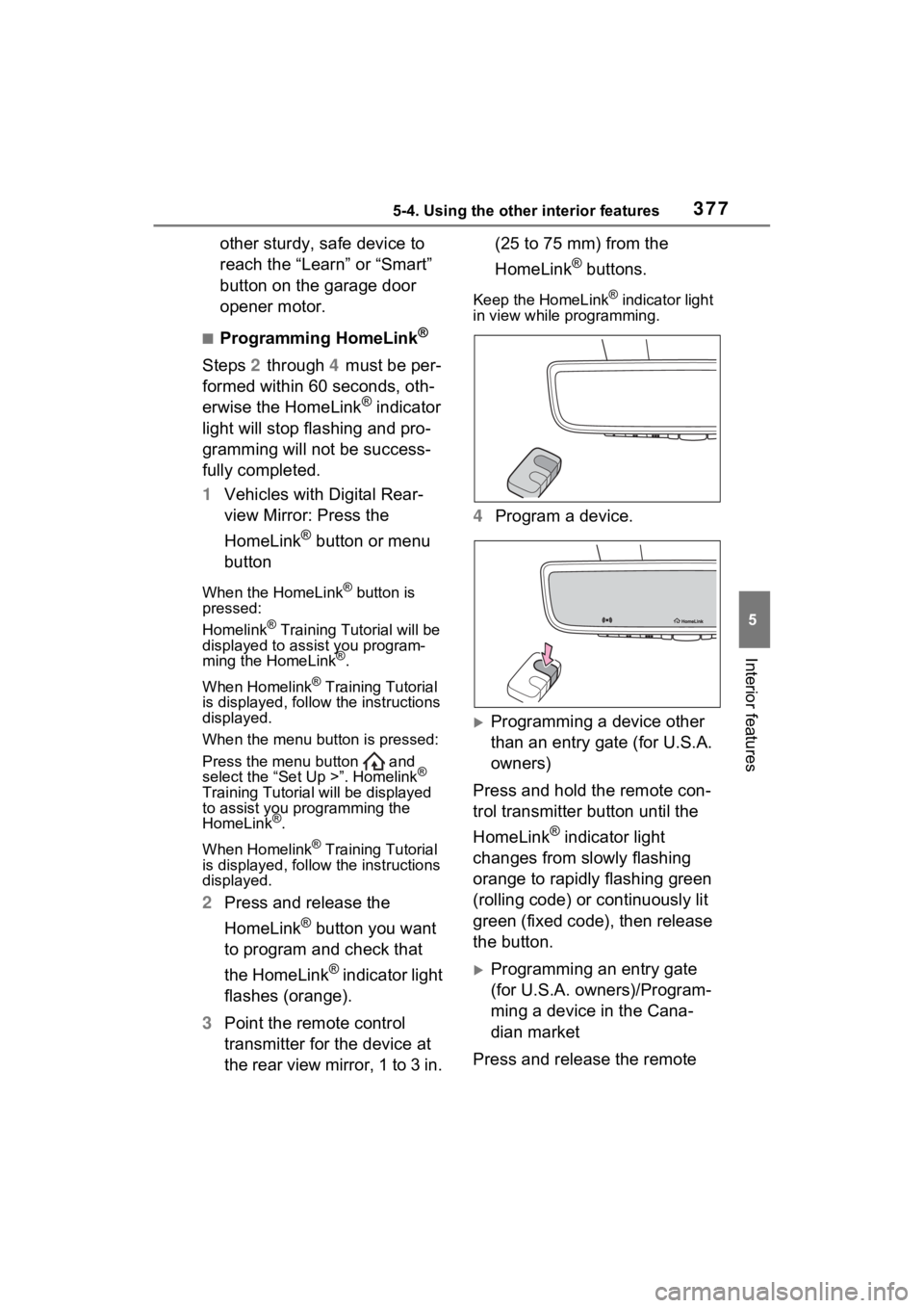
■Programming HomeLink®
Steps 2 through 4 must be per-
formed within 60 seconds, oth-
erwise the HomeLink
® indicator
light will stop flashing and pro-
gramming will not be success-
fully completed.
1 Vehicles with Digital Rear-
view Mirror: Press the
HomeLink
® button or menu
button
When the HomeLink® button is
pressed:
Homelink
® Training Tutorial will be
displayed to assist you program-
ming the HomeLink
®.
When Homelink
® Training Tutorial
is displayed, follow the instructions
displayed.
When the menu button is pressed:
Press the menu button and
select the “Set Up >”. Homelink
®
Training Tutorial will be displayed
to assist you programming the
HomeLink
®.
When Homelink
® Training Tutorial
is displayed, follow the instructions
displayed.
2 Press and release the
HomeLink
® button you want
to program and check that
the HomeLink
® indicator light
flashes (orange).
3 Point the remote control
transmitter for the device at
the rear view mirror, 1 to 3 in. (25 to 75 mm) from the
HomeLink
® buttons.
Keep the HomeLink® indicator light
in view while programming.
4 Program a device.
Programming a device other
than an entry gate (for U.S.A.
owners)
Press and hold the remote con-
trol transmitter button until the
HomeLink
® indicator light
changes from slowly flashing
orange to rapidly flashing green
(rolling code) or continuously lit
green (fixed code), then release
the button.
Programming an entry gate
(for U.S.A. owners)/Program-
ming a device in the Cana-
dian market
Press and release the remote
Page 393 of 586
3916-2. Maintenance
6
Maintenance and care
■Resetting the message indicat-
ing maintenance is required
(with 7-inch display)
After the required maintenance is
performed according to the mainte-
nance schedule, please reset the
reminder light or message.
To reset the reminder light or mes-
sage, follow the procedure
described below:
1 Press or of the meter
control switches and select
on the multi-information display.
2 Press or of the meter
control switches and select
“Vehicle Settings”. Then press
and hold .
3 Press or of the meter
control switches and select
“Scheduled Maintenance”. Then
press .
4 Select “Yes” and press .
A message will be displayed when
the reset proced ure has been com-
pleted.
■Resetting the message indicat-
ing maintenance is required
(with 12.3-inch display)
After the required maintenance is
performed according to the mainte-
nance schedule, please reset the
reminder light or message.
To reset the reminder light or mes-
sage, follow the procedure
described below:
1 Press and hold to display the
cursor on the content display
area (center) of the multi-infor-
mation display. 2
Press or of the meter
control switches to select
and then press .
3 Press or of the meter
control switch es and select
“ Vehicle Settings”. Then
press and hold .
4 Press or of the meter
control switch es and select
“Scheduled Maintenance”. Then
press .
5 Select “Yes” and press .
A message will be d isplayed when
the reset procedure has been com-
pleted.
You can perform some mainte-
nance procedures by yourself.
Please be aware that do-it-your-
self maintenance may affect
warranty coverage.
The use of Toyota Repair Manuals
is recommended.
For details about warranty cover-
age, refer to the separate “Owner’s
Warranty Informat ion Booklet” or
“Owner’s Manual Supplement”.
Do-it-yourself mainte-
nance
Page 399 of 586
3976-3. Do-it-yourself maintenance
6
Maintenance and care
Hybrid bat-
tery (traction
battery) air
intake vent
( P.426)• Vacuum cleaner,
etc,
• Phillips screw- driver
Light bulbs
( P.439)
• Bulb with same
number and watt-
age rating as origi-
nal
• Phillips-head screwdriver
• Flathead screw- driver
• Wrench
Headlight aim
( P.438)• Phillips-head
screwdriver
Radiator and
condenser
( P.404)
Tire inflation
pressure
( P.420)• Tire pressure
gauge
• Compressed air source
Washer fluid
( P.406)
• Water or washer
fluid containing
antifreeze (for win-
ter use)
• Funnel (used only for adding water or
washer fluid)
WARNING
The engine compartment contains
many mechanisms and fluids that
may move suddenly, become hot,
or become electrically energized.
To avoid death or serious injury,
observe the following precautions.
ItemsParts and tools■When working on the engine
compartment
●Make sure that “IGNITION ON”
on the multi-information display
and the “READY” indicator are
both off.
●Keep hands, clothing and tools
away from the moving fan.
●Be careful not to touch the
engine, power control unit, radi-
ator, exhaust manifold, etc. right
after driving as they may be hot.
Oil and other fluids may also be
hot.
●Do not leave anything that may
burn easily, such as paper and
rags, in the engine compart-
ment.
●Do not smoke, cause sparks or
expose an open flame to fuel.
Fuel fumes are flammable.
■When working near the elec-
tric cooling fan or radiator
grille
Be sure the power switch is OFF.
With the power switch in ON, the
electric cooling fa n may automati-
cally start to run if the air condi-
tioning is on and/or the coolant
temperature is high. ( P.404)
■Safety glasses
Wear safety gla sses to prevent
flying or falling material, fluid
spray, etc., from getting in your
eyes.
NOTICE
■If you remove the air cleaner
filter
Driving with the air cleaner filter
removed may cause excessive
engine wear due to dirt in the air.
Page 408 of 586
4066-3. Do-it-yourself maintenance
■Brake fluid can absorb moisture
from the air
Excess moisture in the brake fluid
can cause a dangerous loss of brak-
ing efficiency. Use only newly
opened brake fluid.
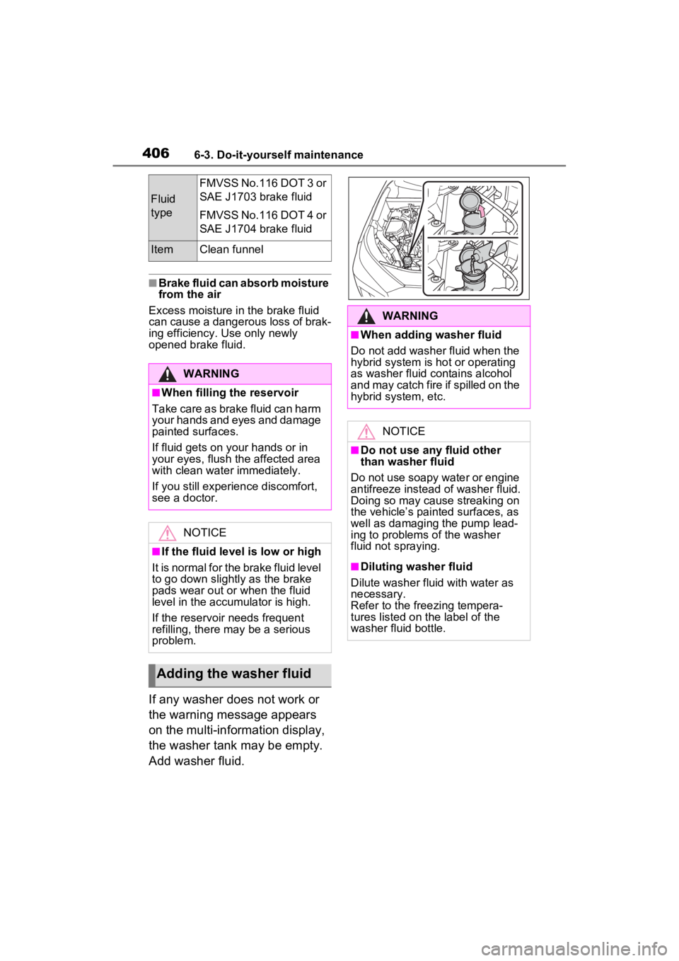
If any washer does not work or
the warning message appears
on the multi-information display,
the washer tank may be empty.
Add washer fluid.
Fluid
type
FMVSS No.116 DOT 3 or
SAE J1703 brake fluid
FMVSS No.116 DOT 4 or
SAE J1704 brake fluid
ItemClean funnel
WARNING
■When filling the reservoir
Take care as brake fluid can harm
your hands and eyes and damage
painted surfaces.
If fluid gets on your hands or in
your eyes, flush th e affected area
with clean water immediately.
If you still experien ce discomfort,
see a doctor.
NOTICE
■If the fluid level is low or high
It is normal for the brake fluid level
to go down slightly as the brake
pads wear out or when the fluid
level in the accumulator is high.
If the reservoir needs frequent
refilling, there may be a serious
problem.
Adding the washer fluid
WARNING
■When adding washer fluid
Do not add washer fluid when the
hybrid system is hot or operating
as washer fluid contains alcohol
and may catch fire if spilled on the
hybrid system, etc.
NOTICE
■Do not use any fluid other
than washer fluid
Do not use soapy water or engine
antifreeze instead of washer fluid.
Doing so may cause streaking on
the vehicle’s painted surfaces, as
well as damaging the pump lead-
ing to problems of the washer
fluid not spraying.
■Diluting washer fluid
Dilute washer fluid with water as
necessary.
Refer to the freezing tempera-
tures listed on the label of the
washer fluid bottle.
Page 414 of 586
4126-3. Do-it-yourself maintenance
■When rotating the tires (vehi-
cles with tire pressure warning
system)
Make sure that the power switch is
OFF. If the tires are rotated while
the power switch is in ON, the tire
position informa tion will not be
updated. If this accidentally occurs,
either turn the power switch to OFF
and then to ON, or initialize the sys-
tem after checking that the tire pres-
sure is properly adjusted.
Your vehicle is equipped with a
tire pressure warning system
that uses tire pressure warning
valves and transmitters to detect
low tire inflation pressure before
serious problems arise.
If the tire pressure drops
below a predetermined level,
the driver is warned by a
screen display and a warning
light. ( P.462)
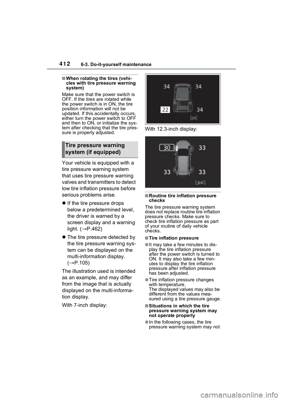
The tire pressure detected by
the tire pressure warning sys-
tem can be displayed on the
multi-information display.
( P.105)
The illustration used is intended
as an example, and may differ
from the image that is actually
displayed on the multi-informa-
tion display.
With 7-inch display: With 12.3-inch display:
■Routine tire inflation pressure
checks
The tire pressure warning system
does not replace routine tire inflation
pressure checks . Make sure to
check tire inflation pressure as part
of your routine o f daily vehicle
checks.
■Tire inflation pressure
●It may take a few minutes to dis-
play the tire inflation pressure
after the power switch is turned to
ON. It may also take a few min-
utes to display the tire inflation
pressure after infl ation pressure
has been adjusted.
●Tire inflation pressure changes
with temperature.
The displayed values may also be
different from the values mea-
sured using a tire pressure gauge.
■Situations in which the tire
pressure warning system may
not operate properly
●In the following cases, the tire
pressure warning system may not
Tire pressure warning
system (if equipped)
Page 415 of 586
4136-3. Do-it-yourself maintenance
6
Maintenance and care
operate properly.
• If non-genuine Toyota wheels are used.
• A tire has been replaced with a tire that is not an OE (Original
Equipment) tire.
• A tire has been replaced with a tire that is not of the specified size.
• Tire chains, etc. are equipped.
• An auxiliary-supported run-flat tire
is equipped.
• If a window tint that affects the
radio wave signals is installed.
• If there is a lot of snow or ice on the vehicle, particularly around the
wheels or wheel housings.
• If the tire inflation pressure is extremely higher than the speci-
fied level.
• If wheels without tire pressure warning valves a nd transmitters
are used.
• If the ID code on the tire pressure warning valves and transmitters is
not registered in the tire pressure
warning computer.
●Performance may be affected in
the following situations.
• Near a TV tower, electric power
plant, gas station , radio station,
large display, airpo rt or other facil-
ity that generates strong radio
waves or electrical noise
• When carrying a portable radio, cellular phone, cordless phone or
other wireless communication
device
If tire position information is not cor-
rectly displayed due to the radio
wave conditions, the display may be
corrected by driving and changing
the radio wave conditions.
●When the vehicle is parked, the
time taken for the warning to start
or go off could be extended.
●When tire inflation pressure
declines rapidly for example when
a tire has burst, the warning may
not function.
■Warning performance of the tire
pressure warning system
The warning of the tire pressure
warning system w ill change in
accordance with the conditions
under which it was initialized. For
this reason, the system may give a
warning even if th e tire pressure
does not reach a low enough level,
or if the pressure is higher than the
pressure that was adjusted to when
the system was initialized.
When replacing tires or wheels,
tire pressure warning valves and
transmitters must also be
installed.
When new tire pressure warning
valves and transmitters are
installed, new ID codes must be
registered in the tire pressure
warning computer and the tire
pressure warning system must
be initialized. ( P.417)
■When replacing the tires and
wheels
If the ID code of the tire pressure
warning valve and tr ansmitter is not
registered, the tire pressure warning
system will not work properly. After
driving for about 20 minutes, the tire
pressure warning light blinks for 1
minute and stays on to indicate a
system malfunction.
Installing tire pressure
warning valves and trans-
mitters (if equipped)
Page 416 of 586
4146-3. Do-it-yourself maintenance
■The tire pressure warning
system must be initialized
in the following circum-
stances:
When rotating the tires.
When changing the tire.
After registering the ID codes.
( P.417)
When the tire pressure warning
system is initialized, the current
tire inflation pressure is set as
the benchmark pressure.
■How to initialize the tire
pressure warning system
(with 7-inch display)
1 Park the vehicle in a safe
place and stop the hybrid
system for 20 minutes or
more.
Initialization cannot be performed
while the vehicle is moving.
2Adjust the tire inflation pres-
sure to the specified cold tire
inflation pressure level.
( P.502)
Make sure to adjust the tire pres-
sure to the specifie d cold tire infla-
tion pressure level. The tire
pressure warning system will oper-
ate based on this pressure level.
3Start the hybrid system.
4 Press or of the meter
control switches on the steer-
ing wheel and select .
5 Press or of the meter
control switches, select
“Vehicle Settings” and then
press and hold .
6 Press or of the meter
control switches, select
“TPWS” and then press .
NOTICE
■Repairing or replacing tires,
wheels, tire pressure warn-
ing valves, transmitters and
tire valve caps
●When removing or fitting the
wheels, tires or the tire pressure
warning valves and transmit-
ters, contact your Toyota dealer
as the tire pr essure warning
valves and transmitters may be
damaged if not handled cor-
rectly.
●Make sure to install the tire
valve caps. If the tire valve caps
are not installed, water could
enter the tire pressure warning
valves and the tire pressure
warning valves could be bound.
●When replacing ti re valve caps,
do not use tire valve caps other
than those specified.
The cap may become stuck.
■To avoid damage to the tire
pressure warning valves and
transmitters
When a tire is repaired with liquid
sealants, the tire pressure warn-
ing valve and transmitter may not
operate properly. If a liquid seal-
ant is used, conta ct your Toyota
dealer as soon as possible. After
use of liquid sealant, make sure to
replace the tire pressure warning
valve and transmitter when repair-
ing or replacing the tire. ( P.413)
Initializing the tire pres-
sure warning system (if
equipped)
Page 417 of 586
4156-3. Do-it-yourself maintenance
6
Maintenance and care
7Press or of the meter
control switches, select the
“Set Pressure”. Then press
and hold .
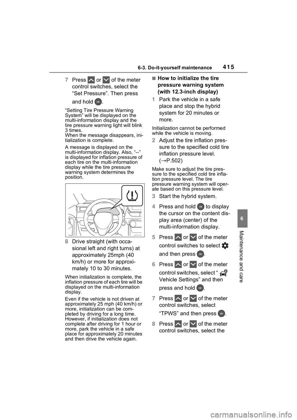
“Setting Tire Pressure Warning
System” will be dis played on the
multi-information display and the
tire pressure warni ng light will blink
3 times.
When the message disappears, ini-
tialization is complete.
A message is displayed on the
multi-information di splay. Also, “--”
is displayed for inflation pressure of
each tire on the multi-information
display while the tire pressure
warning system determines the
position.
8 Drive straight (with occa-
sional left and right turns) at
approximately 25mph (40
km/h) or more for approxi-
mately 10 to 30 minutes.
When initialization is complete, the
inflation pressure of each tire will be
displayed on the multi-information
display.
Even if the vehicle is not driven at
approximately 25 mph (40 km/h) or
more, initializat ion can be com-
pleted by driving for a long time.
However, if initia lization does not
complete after driving for 1 hour or
more, park the vehicle in a safe
place for approximately 20 minutes
and then drive th e vehicle again.
■How to initialize the tire
pressure warning system
(with 12.3-inch display)
1 Park the vehicle in a safe
place and stop the hybrid
system for 20 minutes or
more.
Initialization cannot be performed
while the vehicle is moving.
2Adjust the tire inflation pres-
sure to the specified cold tire
inflation pressure level.
( P.502)
Make sure to adjust the tire pres-
sure to the specifie d cold tire infla-
tion pressure level. The tire
pressure warning system will oper-
ate based on this pressure level.
3Start the hybrid system.
4 Press and hold to display
the cursor on the content dis-
play area (center) of the
multi-information display.
5 Press or of the meter
control switches to select
and then press .
6 Press or of the meter
control switches, select “
Vehicle Settings” and then
press and hold .
7 Press or of the meter
control switches, select
“TPWS” and then press .
8 Press or of the meter
control switches, select the