clock TOYOTA RAV4 PRIME 2021 Owners Manual (in English)
[x] Cancel search | Manufacturer: TOYOTA, Model Year: 2021, Model line: RAV4 PRIME, Model: TOYOTA RAV4 PRIME 2021Pages: 616, PDF Size: 34.66 MB
Page 130 of 616

1302-2. Charging
■Calendar settings
Current date and time information is
automatically set using GPS. How-
ever, if GPS calibra tion of clock is
turned off in the multimedia system
settings, the date needs to be set on
the multi-inform ation display.
If the calendar settings check
screen is displayed when an
attempt was made to register a
charge schedule, check that the cor-
rect date is set. If it is incorrect, be
sure to correct it.
If the calendar information is wrong,
the charging sche dule function will
not operate normally.
When registering the charging
schedule, the following settings
can be changed.
■Select the charging mode
One of the two following
charging modes can be
selected.
“Start”
Starts charging at the set time
*1
and finishes charging when fully
charged.
*2
“Departure”
Starts charging to finish at the
set time.
*3, 4
When this setting is selected,
the air conditioning-linked func-
tion can be used.
*1: Charging schedule function is performed in accordance with
the clock in the multi-information
display. Before registering the
charging schedule, check the
clock settings to the proper time.
*2: There might be a slight error in the timing when charging starts
due to the state of the hybrid bat-
tery (traction battery).
*3: When the system determines that there is no time to finish
charging by the set scheduled
departure time, it starts charging.
Check the charging schedules.
*4: If sudden changes in tempera-ture or changes in the condition
of the power source occur while
charging, charging may not end
exactly at the time estimated by
the system.
■Repeated setting
The periodic charging schedule
can be set by selecting your
desired day of the week. (If no
days are selected, charging is
only carried out once.)
Using the charging
schedule function
Charging can be carried out
at the desired time by regis-
tering the charging sched-
ule. Also, it is possible to
set the charging schedule to
one’s preferences, such as
having charging complete
by a certain departure time
or be carried out at the
same time on certain days.
Settings of the charging
schedule function
Page 149 of 616
1492-2. Charging
2
Plug-in hybrid system
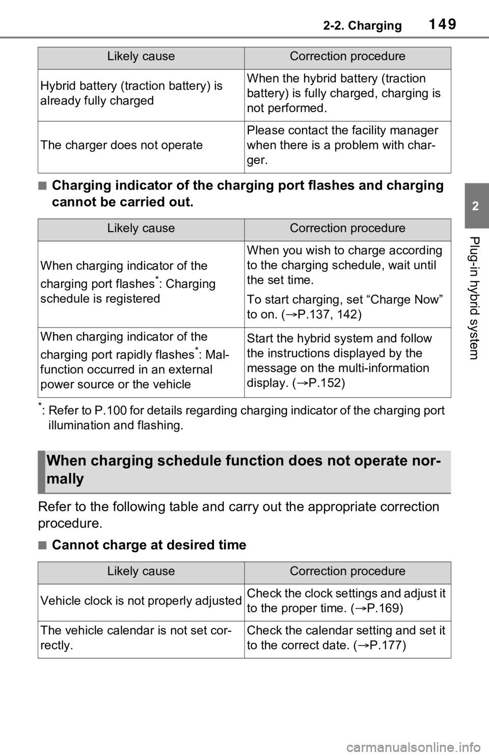
■Charging indicator of the charging port flashes and charging
cannot be carried out.
*: Refer to P.100 for details regarding charging indicator of the charging port
illumination and flashing.
Refer to the following table and carry out the appropriate correction
procedure.
■Cannot charge at desired time
Hybrid battery (traction battery) is
already fully chargedWhen the hybrid battery (traction
battery) is fully char ged, charging is
not performed.
The charger does not operate
Please contact the facility manager
when there is a problem with char-
ger.
Likely causeCorrection procedure
When charging indicator of the
charging port flashes
*: Charging
schedule is registered
When you wish to charge according
to the charging schedule, wait until
the set time.
To start charging, set “Charge Now”
to on. ( P.137, 142)
When charging indicator of the
charging port rapidly flashes
*: Mal-
function occurred in an external
power source or the vehicle
Start the hybrid system and follow
the instructions displayed by the
message on the m ulti-information
display. ( P.152)
When charging schedule func tion does not operate nor-
mally
Likely causeCorrection procedure
Vehicle clock is not properly adjustedCheck the clock settings and adjust it
to the proper time. ( P.169)
The vehicle calendar is not set cor-
rectly.Check the calendar setting and set it
to the correct date. ( P.177)
Likely causeCorrection procedure
Page 165 of 616
1653-1. Instrument cluster
3
Vehicle status information and indicators
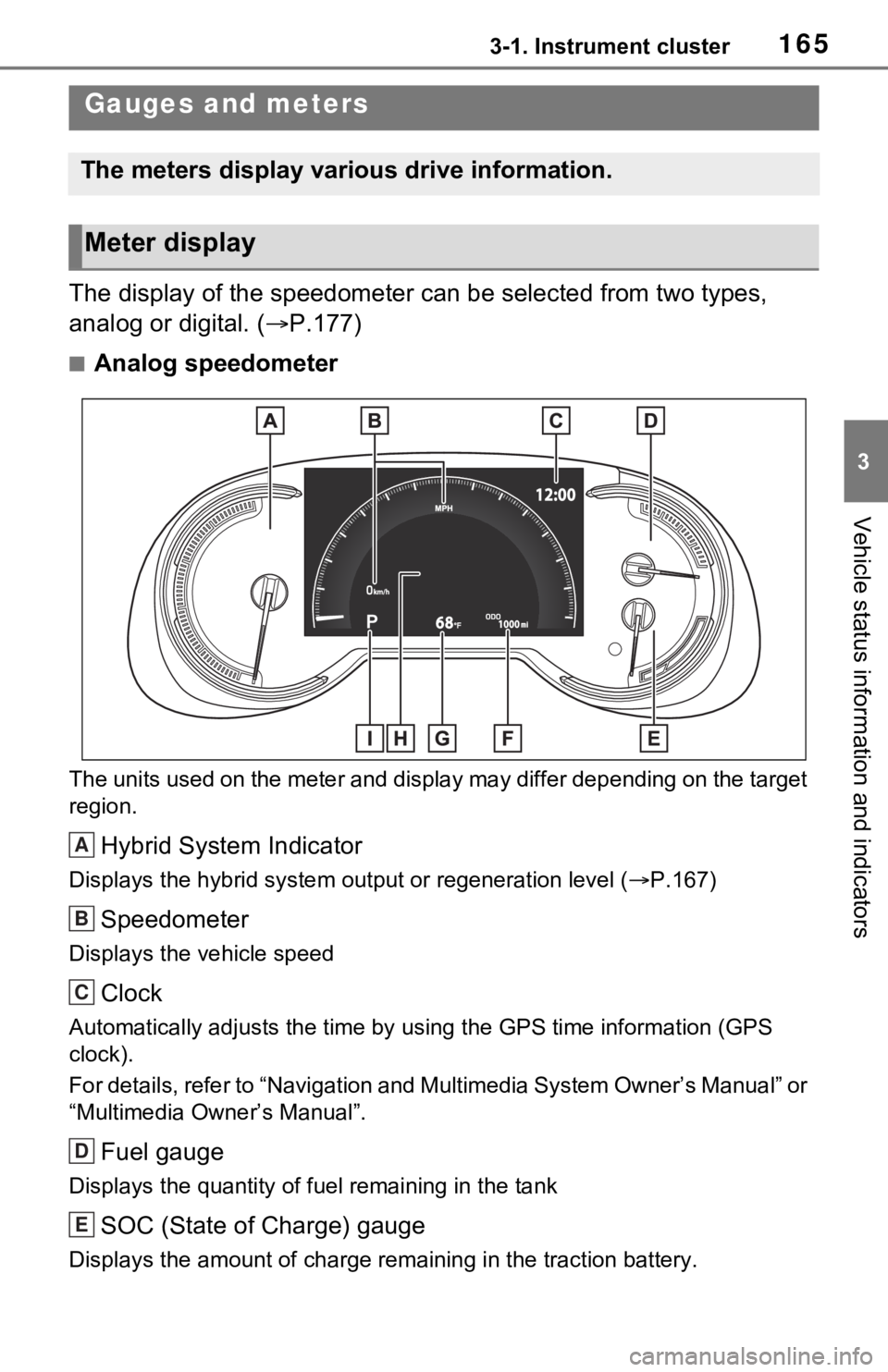
The display of the speedometer can be selected from two types,
analog or digital. ( P.177)
■Analog speedometer
The units used on the meter and display may differ depending on the target
region.
Hybrid System Indicator
Displays the hybrid system output or regeneration level ( P.167)
Speedometer
Displays the vehicle speed
Clock
Automatically adjusts the time by using the GPS time informatio n (GPS
clock).
For details, refer to “Navigation and Multimedia System Owner’s Manual” or
“Multimedia Owner’s Manual”.
Fuel gauge
Displays the quantity of fu el remaining in the tank
SOC (State of Charge) gauge
Displays the amount of charge rem aining in the traction battery.
Gauges and meters
The meters display various drive information.
Meter display
A
B
C
D
E
Page 166 of 616
1663-1. Instrument cluster
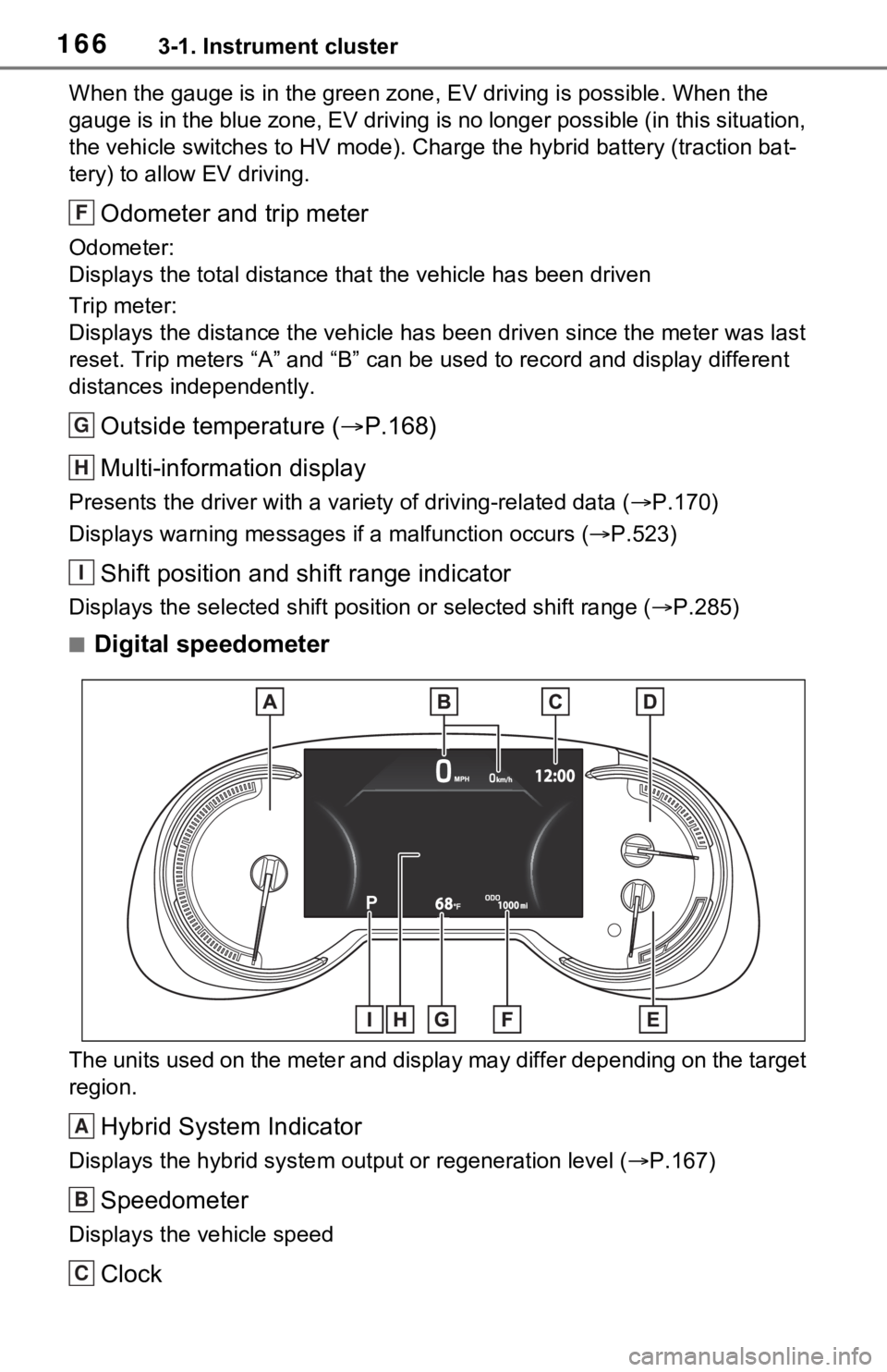
When the gauge is in the green zone, EV driving is possible. When the
gauge is in the blue zone, EV driving is no longer possible (in this situation,
the vehicle switches to HV mode) . Charge the hybrid battery (traction bat-
tery) to allow EV driving.
Odometer and trip meter
Odometer:
Displays the total distance th at the vehicle has been driven
Trip meter:
Displays the distance the vehicle has been driven since the meter was last
reset. Trip meters “A” and “B” c an be used to record and display different
distances independently.
Outside temperature ( P.168)
Multi-information display
Presents the driver with a variety of driving-related data ( P.170)
Displays warning messages if a malfunction occurs (P.523)
Shift position and shift range indicator
Displays the selected shift posit ion or selected shift range (P.285)
■Digital speedometer
The units used on the meter and display may differ depending on the target
region.
Hybrid System Indicator
Displays the hybrid system output or regeneration level ( P.167)
Speedometer
Displays the vehicle speed
Clock
F
G
H
I
A
B
C
Page 167 of 616
1673-1. Instrument cluster
3
Vehicle status information and indicators
Automatically adjusts the time by using the GPS time informatio n (GPS
clock).
For details, refer to “Navigation and Multimedia System Owner’s Manual” or
“Multimedia Owner’s Manual”.
Fuel gauge
Displays the quantity of fu el remaining in the tank
SOC (State of Charge) gauge
Displays the amount of charge rem aining in the traction battery.
When the gauge is in the green zo ne, EV driving is possible. When the
gauge is in the blue zone, EV driving is no longer possible (in this situation,
the vehicle switches to HV mode) . Charge the hybrid battery (traction bat-
tery) to allow EV driving.
Odometer and trip meter
Odometer:
Displays the total distance th at the vehicle has been driven
Trip meter:
Displays the distance the vehicle has been driven since the meter was last
reset. Trip meters “A” and “B” c an be used to record and display different
distances independently.
Outside temperature ( P.168)
Multi-information display
Presents the driver with a variety of driving-related data ( P.170)
Displays warning messages if a malfunction occurs (P.523)
Shift position and shift range indicator
Displays the selected shift posit ion or selected shift range (P.285)
■The meters and display illumi-
nate when
The power swit ch is in ON.
■When changing driving mode
Speedometer color is changed fol-
lowing the selected driving mode or
when Trail Mode is turned on.
( P.377, 379)
■Hybrid System Indicator
The display content s of the Hybrid
System Indicator are different in EV
mode and HV mode.
D
E
F
G
H
I
Page 170 of 616
1703-1. Instrument cluster
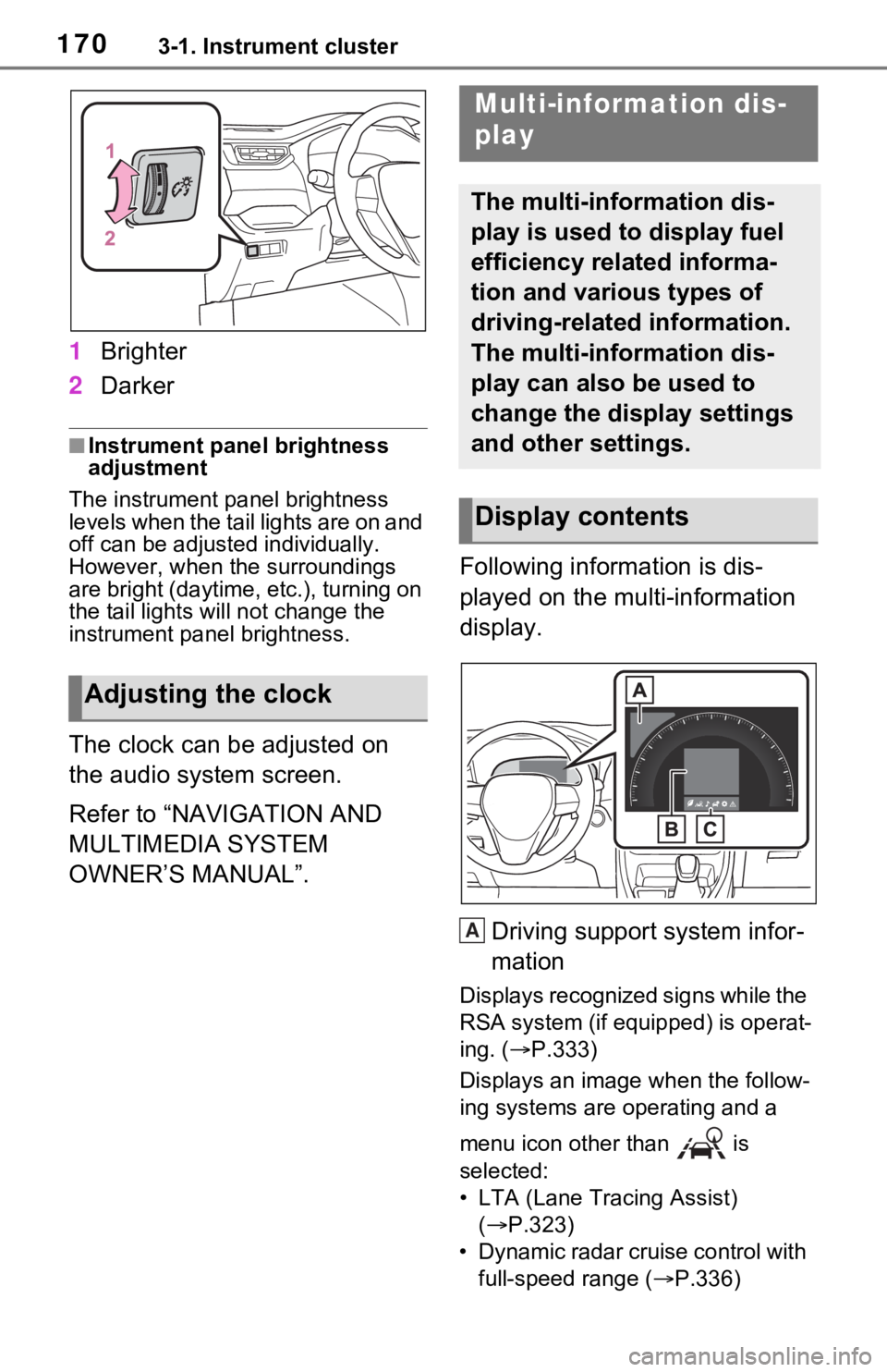
1Brighter
2 Darker
■Instrument panel brightness
adjustment
The instrument panel brightness
levels when the tail lights are on and
off can be adjusted individually.
However, when the surroundings
are bright (daytime, etc.), turning on
the tail lights will not chan ge the
instrument panel brightness.
The clock can be adjusted on
the audio system screen.
Refer to “NAVIGATION AND
MULTIMEDIA SYSTEM
OWNER’S MANUAL”. Following information is dis-
played on the multi-information
display.
Driving support system infor-
mation
Displays recognized signs while the
RSA system (if equipped) is operat-
ing. ( P.333)
Displays an image when the follow-
ing systems are operating and a
menu icon other than is
selected:
• LTA (Lane Tracing Assist) ( P.323)
• Dynamic radar cruise control with full-speed range ( P.336)
Adjusting the clock
Multi-information dis-
play
The multi-information dis-
play is used to display fuel
efficiency related informa-
tion and various types of
driving-related information.
The multi-information dis-
play can also be used to
change the display settings
and other settings.
Display contents
A
Page 180 of 616
1803-1. Instrument cluster
Select to set up the following items.
• “Hybrid System”
Select to enable/disable the ECO
Accelerator Guidance (P.173).
• “Fuel Economy”
Select to change the display on
Fuel Economy ( P.172).
• “Power Consumption”
Select to change the display on
Power Consumption ( P.172).
(Audio settings) (if
equipped)
Select to enable/disable
screen.
(Vehicle information dis-
play settings)
• “Display Contents”
Select to set up the following items.
“Energy monitor”:
Select to enable/disable the Energy
monitor ( P.187)
“AWD”:
Select to enable/disable the AWD
system display ( P.176).
• “Drive Info Type”
Select to change the drive informa-
tion type display between trip and
total. ( P.176).
• “Drive Info Items”
Select to set the items on the upper
and lower side of the drive informa-
tion screen from three items, aver-
age speed, distance and total time.
“Closing Display”
Select to set the i tems displayed
when the power switch is turned off.
“Pop-Up Display” (if
equipped)
Select to enable/d isable the follow-
ing pop-up displays, which may
appear in some situations.
• Intersection guidance display of the navigation s ystem-linked sys-
tem (if equipped)
• Incoming call display of the hands-free phone system (if
equipped)
• Audio operation (if equipped)
• Volume operation (if equipped)
• Voice control (if equipped)
“Calender”
Select to set up the calender.
This can only be set if GPS calibra-
tion of clock is turn ed off in the mul-
timedia system settings.
“MID OFF”
A blank screen is displayed.
“Default Settings”
Select to reset the meter display
settings.
■Suspension of the settings dis-
play
●In the following situations, opera-
tion of the settings display will be
temporarily suspended.
• When a warning message
appears on the multi-information
display
• When the vehicle begins to move
●Settings for functions not
equipped to the vehicle are not
displayed.
●When a function is turned off, the
related settings for that function
are not selectable.
Page 396 of 616
3966-1. Using the air conditioning system and defogger
6-1.Using the air conditioning system and defogger
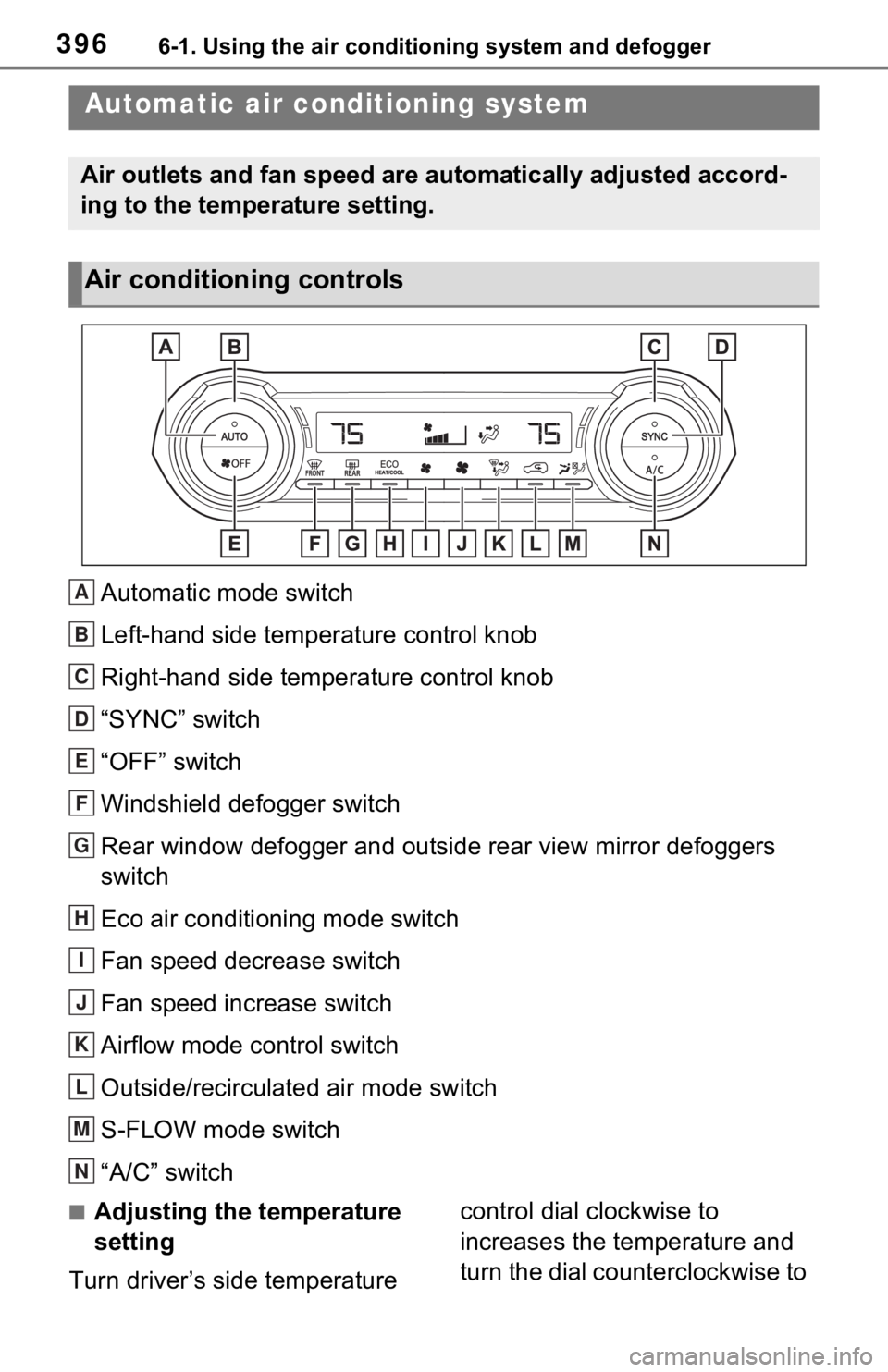
Automatic mode switch
Left-hand side temperature control knob
Right-hand side temperature control knob
“SYNC” switch
“OFF” switch
Windshield defogger switch
Rear window defogger and outside rear view mirror defoggers
switch
Eco air conditioning mode switch
Fan speed decrease switch
Fan speed increase switch
Airflow mode control switch
Outside/recirculated air mode switch
S-FLOW mode switch
“A/C” switch
■Adjusting the temperature
setting
Turn driver’s side temperature control dial clockwise to
increases the temperature and
turn the dial counterclockwise to
Automatic air co
nditioning system
Air outlets and fan speed are automatically adjusted accord-
ing to the temperature setting.
Air conditioning controls
A
B
C
D
E
F
G
H
I
J
K
L
M
N
Page 461 of 616
4617-3. Do-it-yourself maintenance
7
Maintenance and care
check the oil level on the dip-
stick.
■Checking the engine oil
1 Park the vehicle on level
ground. After warming up the
engine and turning off the
hybrid system, wait more
than 5 minutes for the oil to
drain back into the bottom of
the engine.
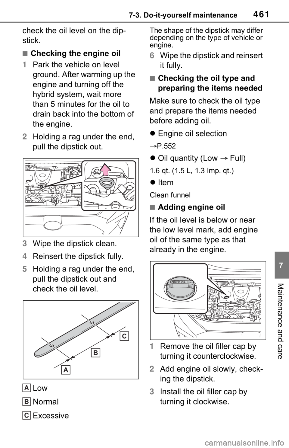
2 Holding a rag under the end,
pull the dipstick out.
3 Wipe the dipstick clean.
4 Reinsert the dipstick fully.
5 Holding a rag under the end,
pull the dipstick out and
check the oil level.
Low
Normal
Excessive
The shape of the dipstick may differ
depending on the type of vehicle or
engine.
6Wipe the dipstick and reinsert
it fully.
■Checking the oil type and
preparing the items needed
Make sure to check the oil type
and prepare the items needed
before adding oil.
Engine oil selection
P.552
Oil quantity (Low Full)
1.6 qt. (1.5 L, 1.3 Imp. qt.)
Item
Clean funnel
■Adding engine oil
If the oil level is below or near
the low level mark, add engine
oil of the same type as that
already in the engine.
1 Remove the oil filler cap by
turning it counterclockwise.
2 Add engine oil slowly, check-
ing the dipstick.
3 Install the oil filler cap by
turning it clockwise.
A
B
C
Page 498 of 616
4987-3. Do-it-yourself maintenance
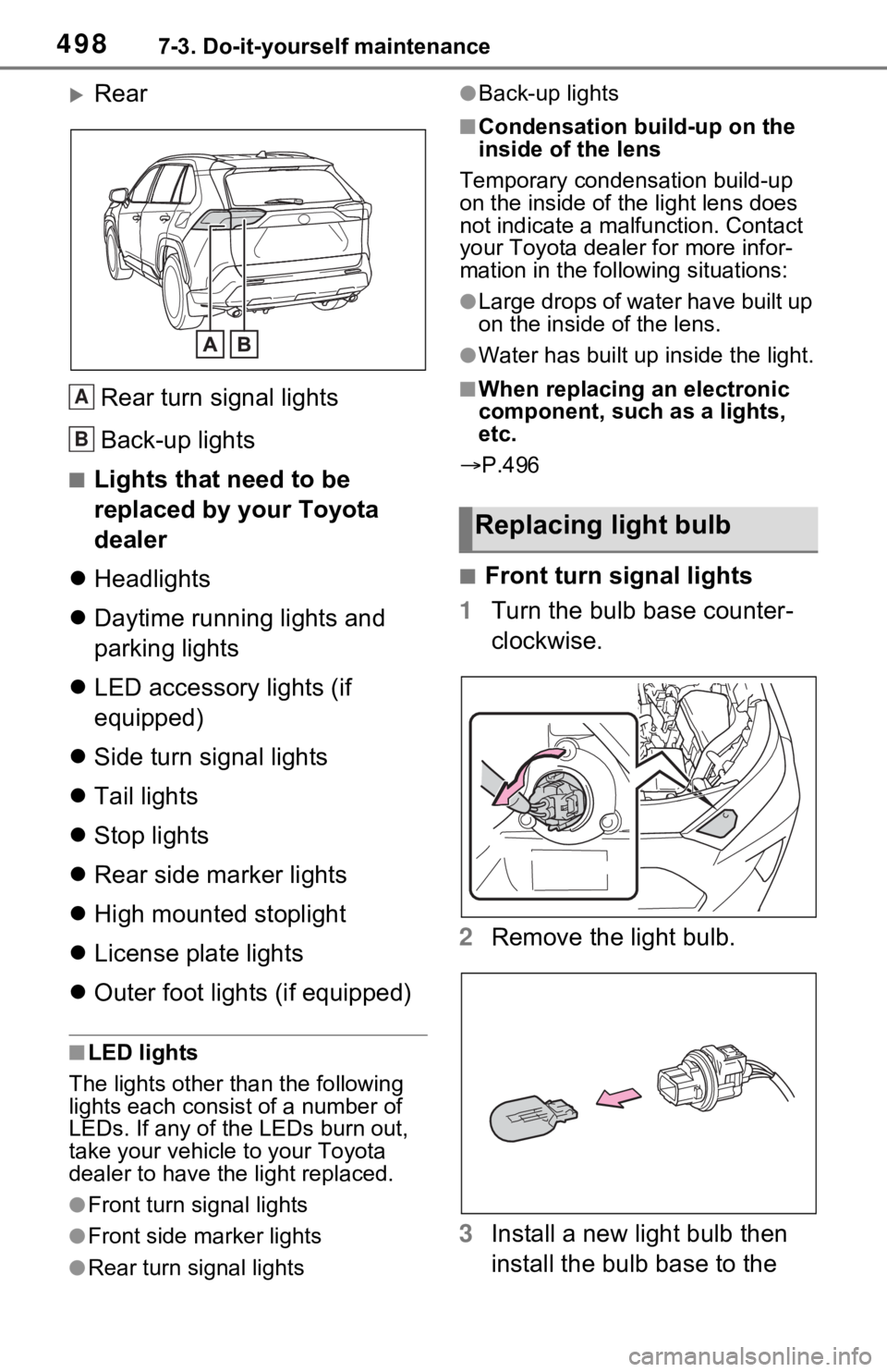
Rear
Rear turn signal lights
Back-up lights
■Lights that need to be
replaced by your Toyota
dealer
Headlights
Daytime running lights and
parking lights
LED accessory lights (if
equipped)
Side turn signal lights
Tail lights
Stop lights
Rear side marker lights
High mounted stoplight
License plate lights
Outer foot lights (if equipped)
■LED lights
The lights other than the following
lights each consist of a number of
LEDs. If any of the LEDs burn out,
take your vehicle to your Toyota
dealer to have the light replaced.
●Front turn signal lights
●Front side marker lights
●Rear turn signal lights
●Back-up lights
■Condensation build-up on the
inside of the lens
Temporary condensation build-up
on the inside of the light lens does
not indicate a mal function. Contact
your Toyota dealer for more infor-
mation in the following situations:
●Large drops of water have built up
on the inside of the lens.
●Water has built up inside the light.
■When replacing an electronic
component, such as a lights,
etc.
P.496
■Front turn signal lights
1 Turn the bulb base counter-
clockwise.
2 Remove the light bulb.
3 Install a new light bulb then
install the bulb base to the
A
B
Replacing light bulb