warning light TOYOTA RAV4 PRIME 2021 Owners Manual (in English)
[x] Cancel search | Manufacturer: TOYOTA, Model Year: 2021, Model line: RAV4 PRIME, Model: TOYOTA RAV4 PRIME 2021Pages: 616, PDF Size: 34.66 MB
Page 522 of 616
5228-2. Steps to take in an emergency
■Warning messages
The warning messages explained
below may differ from the actual
messages according to operation
conditions and vehicle specifica-
tions.
■If a message about an operation
is shown
●If a message about an operation
of the accelerator pedal or brake
Your vehicle has also been
equipped with a TPMS (tire pres-
sure warning system) malfunc-
tion indicator to indicate when the
system is not opera
ting properly.
The TPMS (tire pressure warning
system) malfunction indicator is
combined with the low tire pres-
sure telltale (tire pressure warning
light). When the system detects a
malfunction, the telltale will flash
for approximately one minute and
then remain continuously illumi-
nated. This sequence will con-
tinue upon subsequent vehicle
start-ups as long as the malfunc-
tion exists. When the malfunction
indicator is illuminated, the sys-
tem may not be able to detect or
signal low tire pressure as
intended.
TPMS (tire pressure warning sys-
tem) malfunctions may occur for a
variety of reasons, including the
installation of replacement or
alternate tires or wheels on the
vehicle that prevent the TPMS
(tire pressure warning system)
from functioning properly. Always
check the TPMS ( tire pressure
warning system) malfunction tell-
tale after replacing one or more
tires or wheels on your vehicle to
ensure that the r eplacement or
alternate tires and wheels allow
the TPMS (tire pressure warning
system) to continue to function
properly.
NOTICE
■To ensure the tire pressure
warning system operates
properly
Do not install tires with different
specifications or manufacturers
as the tire pressure warning sys-
tem may not operate properly.
If a warning message
is displayed
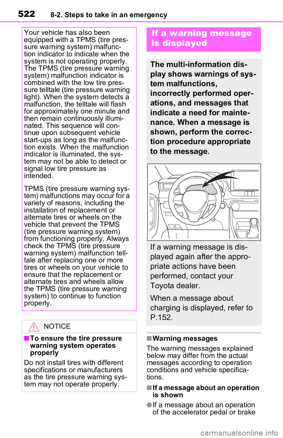
The multi-information dis-
play shows warnings of sys-
tem malfunctions,
incorrectly performed oper-
ations, and messages that
indicate a need for mainte-
nance. When a message is
shown, perform the correc-
tion procedure appropriate
to the message.
If a warning message is dis-
played again after the appro-
priate actions have been
performed, contact your
Toyota dealer.
When a message about
charging is displayed, refer to
P.152.
Page 523 of 616

5238-2. Steps to take in an emergency
8
When trouble arises
pedal is shown
A warning message about an opera-
tion of the brake pedal may be
shown while the dr iving support sys-
tems such as PCS (Pre-Collision
system) or the dynamic radar cruise
control with full-speed range is oper-
ating. If a warning message is
shown, be sure to decelerate the
vehicle or follow an instruction
shown on the multi -information dis-
play.
• A warning message is shown when Brake Override System
operates. ( P.259, 517)
• A warning message is shown when Drive-Start Control or Park-
ing Support Brake function (if
equipped) operates ( P.259,
363). Follow the instructions on
the multi-inform ation display.
●If a message about an operation
of the power switch is shown
An instruction for operation of the
power switch is shown when the
incorrect procedure for starting the
hybrid system is performed or the
power switch is operated incorrectly.
Follow the instructions shown on the
multi-information display to operate
the power switch again.
●If a message abou t a shift lever
operation is shown
To prevent the shift lever from being
operated incorrectly or the vehicle
from moving unexpectedly, a mes-
sage that requires shifting the shift
lever may be sho wn on the multi-
information display. In that case, fol-
low the instruction of the message
and shift the shift lever.
●If a message or image about an
open/close state of a part or
replenishment of a consumable is
shown
Confirm the part indicated by the multi-information
display or a warn-
ing light, and then perform the cop-
ing method such as closing the
open door or replenishing a con-
sumable.
■If a message that indicates the
need for visiting your Toyota
dealer is displayed
The system or part shown on the
multi-information di splay is malfunc-
tioning. Have the vehicle inspected
by your Toyota dea ler immediately.
■If a message that indicates the
need for referring to Owner’s
Manual is displayed
●If the following messages are
shown, follow the instructions,
accordingly.
• “Blind Spot Monitor Unavailable”
( P.348, 523)
• “Rear Cross Traffic Alert Unavail- able”( P.348, 523)
• “Engine Coolant Temp High” ( P.544)
●If the following messages are
shown, there may be a malfunc-
tion. Immediately stop the vehicle
in a safe place and contact your
Toyota dealer. Continuing to drive
the vehicle may be dangerous.
• “Plug-in charging system malfunc- tion”
• “Hybrid System Malfunction”
• “Charging System Malfunction”
• “Check Engine”
• “Hybrid Battery System Malfunc-
tion”
• “Accelerator System Malfunction”
• “Smart Key System Malfunction”
●If the following messages are
shown, there may be a malfunc-
tion. Immediately have the vehi-
cle inspected by your Toyota
dealer.
• “Oil Pressure Low”
• “Braking Power Low”
●If any of the following messages
are shown on the multi-informa-
tion display, the vehicle may have
run out of fuel. Stop the vehicle in
Page 525 of 616
5258-2. Steps to take in an emergency
8
When trouble arises
recharge the 12-volt battery.
■If “Engine Oil Level Low Add or
Replace” is displayed
The engine oil level may be low.
Check the level of the engine oil,
and add engine oil if necessary.
This message may be displayed if
the vehicle is sto pped on a slope.
Move the vehicle to a level surface
and check if the message disap-
pears.
■If “Maintenance Required
Soon” is shown
Indicates that all maintenance
according to the driven distance on
the maintenance schedule
* should
be performed soon.
Comes on approximately 4500
miles (7200 km) after the message
has been reset.
If necessary, perform maintenance.
Please reset the message after the
maintenance is performed.
( P.451)
*: Refer to the separate “Scheduled
Maintenance Guide” or “Owner’
Manual Supplement” for the main-
tenance interval applicable to your
vehicle.
■If “Maintenance Required Visit
Your Dealer” is shown
Indicates that all maintenance is
required to correspond to the driven
distance on the maintenance sched-
ule
*.
Comes on approximately 5000
miles (8000 km) after the message
has been reset. (The indicator will
not work properly unless the mes-
sage has been reset.)
Perform the necessary mainte-
nance. Please reset the message
after the maintenance is performed.
( P.451)
*: Refer to the separate “Scheduled
Maintenance Guide” or “Owner’
Manual Supplement” for the main- tenance interval applicable to your
vehicle.
■If a message that indicates the
malfunction of front camera is
displayed
The following systems may be sus-
pended until the problem shown in
the message is resolved. ( P.313,
511)
●PCS (Pre-Collision System)
●LTA (Lane Tracing Assist)
●Automatic High Beam
●RSA (Road Sign Assist)*
●Dynamic radar cruise control with
full-speed range
*: If equipped
■If “Radar Cruise Control
Unavailable See Owner’s Man-
ual” is shown
The dynamic radar cruise control
with full-speed range system is sus-
pended temporarily or until the prob-
lem shown in the message is
resolved. (causes and coping meth-
ods: P.313)
■If “Radar Cruise Control
Unavailable” is shown
The dynamic radar cruise control
with full-speed range system cannot
be used temporarily. Use the sys-
tem when it becomes available
again.
■Warning buzzer
P.519
WARNING
■If a warning light comes on or
a warning buzzer sounds
when a warning message is
shown on the multi-informa-
tion display
P.521
Page 530 of 616
5308-2. Steps to take in an emergency
and then take out the spare
tire.
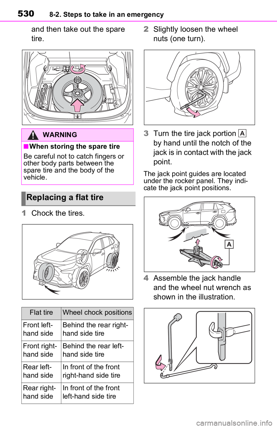
1 Chock the tires. 2
Slightly loosen the wheel
nuts (one turn).
3 Turn the tire jack portion
by hand until the notch of the
jack is in contact with the jack
point.
The jack point guides are located
under the rocker panel. They indi-
cate the jack po int positions.
4Assemble the jack handle
and the wheel nut wrench as
shown in the illustration.
WARNING
■When storing the spare tire
Be careful not to catch fingers or
other body parts between the
spare tire and the body of the
vehicle.
Replacing a flat tire
Flat tireWheel chock positions
Front left-
hand sideBehind the rear right-
hand side tire
Front right-
hand sideBehind the rear left-
hand side tire
Rear left-
hand sideIn front of the front
right-hand side tire
Rear right-
hand sideIn front of the front
left-hand side tire
A
Page 531 of 616

5318-2. Steps to take in an emergency
8
When trouble arises
5Raise the vehicle until the tire
is slightly raised off the
ground.
6 Remove all the wheel nuts
and the tire.
When resting the tire on the
ground, place the tire so that the
wheel design faces up to avoid
scratching the wheel surface.
1 Remove any dirt or foreign
matter from the wheel con-
tact surface.
If foreign matter is on the wheel
contact surface, the wheel nuts
may loosen while the vehicle is in
WARNING
■Replacing a flat tire
●Do not touch the disc wheels or
the area around the brakes
immediately after the vehicle
has been driven.
After the vehicle has been
driven the disc wheels and the
area around the brakes will be
extremely hot. Touching these
areas with hands , feet or other
body parts while changing a tire,
etc. may result in burns.
●Failure to follow these precau-
tions could cause the wheel
nuts to loosen and the tire to fall
off, resulting in death or serious
injury.
• Have the wheel nuts tightened
with a torque wrench to 76 ft•lbf
(103 N•m, 10.5 kgf•m) as soon
as possible after changing
wheels.
• When installing a tire, only use wheel nuts that have been spe-
cifically designed for that wheel.
• If there are any cracks or defor- mations in the bolt screws, nut
threads or bolt holes of the
wheel, have the vehicle
inspected by your Toyota
dealer.
●For vehicles with power back
door: In cases such as when
replacing tires, make sure to
turn off the po wer back door
system ( P.216). Failure to do
so may cause the back door to
operate unintentionally if the
power back door switch is acci-
dentally touched , resulting in
hands and fingers being caught
and injured.
Installing the spare tire
Page 532 of 616
5328-2. Steps to take in an emergency
motion, causing the tire to come off.
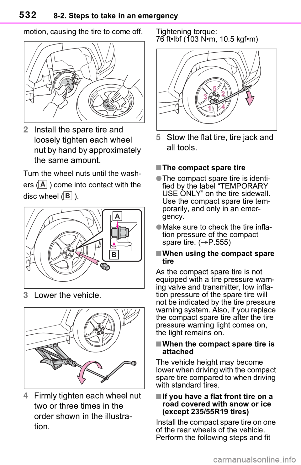
2Install the spare tire and
loosely tighten each wheel
nut by hand by approximately
the same amount.
Turn the wheel nuts until the wash-
ers ( ) come into contact with the
disc wheel ( ).
3Lower the vehicle.
4 Firmly tighten each wheel nut
two or three times in the
order shown in the illustra-
tion.
Tightening torque:
76 ft•lbf (103 N•m, 10.5 kgf•m)
5Stow the flat tire, tire jack and
all tools.
■The compact spare tire
●The compact spare tire is identi-
fied by the label “TEMPORARY
USE ONLY” on the tire sidewall.
Use the compact spare tire tem-
porarily, and only in an emer-
gency.
●Make sure to check the tire infla-
tion pressure of the compact
spare tire. ( P.555)
■When using the compact spare
tire
As the compact spare tire is not
equipped with a tire pressure warn-
ing valve and transm itter, low infla-
tion pressure of t he spare tire will
not be indicated by the tire pressure
warning system. Also , if you replace
the compact spare ti re after the tire
pressure warning light comes on,
the light remains on.
■When the compact spare tire is
attached
The vehicle height may become
lower when driving with the compact
spare tire compared to when driving
with standard tires.
■If you have a flat front tire on a
road covered wit h snow or ice
(except 235/55R19 tires)
Install the compact spare tire on one
of the rear wheels of the vehicle.
Perform the following steps and fit
A
B
Page 533 of 616

5338-2. Steps to take in an emergency
8
When trouble arises
tire chains to the front tires:
1Replace a rear tire with the com-
pact spare tire.
2 Replace the flat front tire with the
tire removed from the rear of the
vehicle.
3 Fit tire chains to the front tires.
WARNING
■When using the compact
spare tire
●Remember that the compact
spare tire provided is specifi-
cally designed for use with your
vehicle. Do not use your com-
pact spare tire on another vehi-
cle.
●Do not use more than one com-
pact spare tire simultaneously.
●Replace the compact spare tire
with a standard tire as soon as
possible.
●Avoid sudden acceleration,
abrupt steering, sudden brak-
ing and shifting operations that
cause sudden engine braking.
■When the compact spare tire
is attached
The vehicle speed may not be
correctly detecte d, and the follow-
ing systems may not operate cor-
rectly:
• ABS & Brake assist
• VSC/Trailer Sway Control
• TRAC
• Dynamic radar cruise control with full-speed range
• PCS (Pre-Collision System)
• EPS
• LTA (Lane Tracing Assist)
• Tire pressure warning system
• AHB (Automatic High Beam)
• AFS (Adaptive Front-lighting System) (if equipped)
• BSM (Blind Spot Monitor)
• Rear view monitor system (if equipped)
• Panoramic view monitor (if equipped)
• Toyota parking assist monitor (if equipped)
• Intuitive parking assist (if equipped)
• PKSB (Parking Support Brake) (if equipped)
• Navigation system (if equipped)
Also, not only c an the following
system not be utilized fully, but it
may actually negatively affect the
drive-train components:
• E-Four (Electronic On-Demand AWD system)
■Speed limit when using the
compact spare tire
Do not drive at speeds in excess
of 50 mph (80 km /h) when a com-
pact spare tire is installed on the
vehicle.
The compact spare tire is not
designed for driving at high
speeds. Failure to observe this
precaution may lead to an acci-
dent causing death or serious
injury.
■After using the tools and jack
Before driving, ma ke sure all the
tools and jack are securely in
place in their storage location to
reduce the possibility of personal
injury during a collision or sudden
braking.
Page 543 of 616
5438-2. Steps to take in an emergency
8
When trouble arises
WARNING
■Avoiding 12-volt battery fires
or explosions
Observe the following precautions
to prevent accidentally igniting the
flammable gas that may be emit-
ted from the 12-volt battery:
●Make sure each jumper cable is
connected to the correct termi-
nal and that it is not unintention-
ally in contact with any other
than the intended terminal.
●Do not allow the other end of
the jumper cable connected to
the “+” terminal to come into
contact with any other parts or
metal surfaces in the area, such
as brackets or unpainted metal.
●Do not allow the + and - clamps
of the jumper cables to come
into contact with each other.
●Do not smoke, use matches,
cigarette lighters or allow open
flame near the 12-volt battery.
■12-volt battery precautions
The 12-volt battery contains poi-
sonous and corrosi ve acidic elec-
trolyte, while related parts contain
lead and lead compounds.
Observe the following precautions
when handling the 12-volt battery:
●When working with the 12-volt
battery, always wear safety
glasses and take care not to
allow any battery fluids (acid) to
come into contact with skin,
clothing or the vehicle body.
●Do not lean over the 12-volt bat-
tery.
●In the event that battery fluid
comes into contact with the skin
or eyes, immediately wash the
affected area with water and
seek medical attention.
Place a wet sponge or cloth
over the affected area until
medical attention can be
received.
●Always wash your hands after
handling the 12-volt battery sup-
port, terminals, and other bat-
tery-related parts.
●Do not allow children near the
12-volt battery.
■After recharging the 12-volt
battery
Have the 12-volt battery
inspected at your Toyota dealer
as soon as possible.
If the 12-volt battery is deteriorat-
ing, continued use may cause the
12-volt battery to emit a malodor-
ous gas, which may be detrimen-
tal to the health of passengers.
■When replacing the 12-volt
battery
●For information regarding 12-
volt battery rep lacement, con-
tact your Toyota dealer.
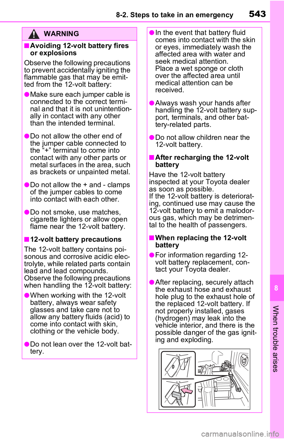
●After replacing, s ecurely attach
the exhaust hose and exhaust
hole plug to the exhaust hole of
the replaced 12-volt battery. If
not properly installed, gases
(hydrogen) may leak into the
vehicle interior, and there is the
possible danger of the gas ignit-
ing and exploding.
Page 544 of 616
5448-2. Steps to take in an emergency
■If the high coolant tempera-
ture warning light comes
on, flashes or “Engine
Coolant Temp High Stop in
a Safe Place See Owner’s
Manual” is shown on the
multi-information display
1 Stop the vehicle in a safe
place and turn off the air con-
ditioning system, and then
stop the hybrid system.
2 If you see steam:
Carefully lift the hood after
NOTICE
■When handling jumper cables
When connecting the jumper
cables, ensure that they do not
become entangled in the cooling
fan, etc.
■To prevent damaging the
vehicle
The exclusive jump starting termi-
nal is to be used when charging
the 12-volt battery from another
vehicle in an emergency. It cannot
be used to jump start another
vehicle.
If your vehicle over-
heats
The following may indicate
that your vehicle is over-
heating.
The high coolant tempera-
ture warning light ( P.161)
comes on or flashes, or a
loss of hybrid system power
is experienced. (For exam-
ple, the vehicle speed does
not increase.)
“Engine Coolant Temp High
Stop in a Safe Place See
Owner’s Manual” or “Hybrid
System Overheated Output
Power Reduced” is shown
on the multi-information dis-
play.
Steam comes out from
under the hood.
Correction procedures
Page 576 of 616
5769-2. Customization
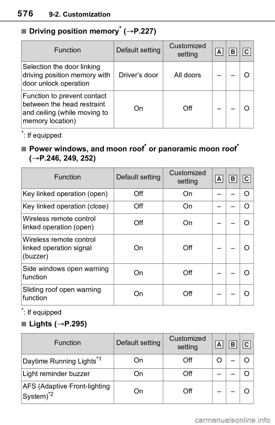
■Driving position memory* ( P.227)
*: If equipped
■Power windows, and moon roof* or panoramic moon roof*
( P.246, 249, 252)
*: If equipped
■Lights ( P.295)
FunctionDefault settingCustomized
setting
Selection the door linking
driving position memory with
door unlock operation
Driver’s doorAll doors––O
Function to prevent contact
between the head restraint
and ceiling (while moving to
memory location)
OnOff––O
FunctionDefault settingCustomized setting
Key linked operation (open)OffOn––O
Key linked operation (close)OffOn––O
Wireless remote control
linked operation (open)OffOn––O
Wireless remote control
linked operation signal
(buzzer)
OnOff––O
Side windows open warning
functionOnOff––O
Sliding roof open warning
function OnOff––O
FunctionDefault settingCustomized setting
Daytime Running Lights*1OnOffO–O
Light reminder buzzerOnOff––O
AFS (Adaptive Front-lighting
System)
*2OnOff––O
ABC
ABC
ABC