TOYOTA RAV4 PRIME 2021 Owners Manual
Manufacturer: TOYOTA, Model Year: 2021, Model line: RAV4 PRIME, Model: TOYOTA RAV4 PRIME 2021Pages: 618, PDF Size: 24.18 MB
Page 481 of 618
4817-3. Do-it-yourself maintenance
7
Maintenance and care
Do not forget to check the spare.
■Effects of incorrect tire inflation
pressure
Driving with incorr ect tire inflation
pressure may result in the following:
●Reduced fuel economy
●Reduced driving comfort and poor
handling
●Reduced tire life due to wear
●Reduced safety
●Damage to the drive train
If a tire needs frequent inflating,
have it checked b y your Toyota
dealer.
■Instructions for checking tire
inflation pressure
When checking tire inflation pres-
sure, observe the following:
●Check only when the tires are
cold.
If your vehicle has been parked
for at least 3 hours or has not
been driven for more than 1 mile
or 1.5 km, you will get an accurate
cold tire inflation pressure reading.
●Always use a tire pressure gauge.
It is difficult to judge if a tire is
properly inflated based only on its
appearance.
●It is normal for th e tire inflation
pressure to be higher after driving
as heat is generated in the tire. Do
not reduce tire inflation pressure
after driving.
●Never exceed the vehicle capacity
weight. Passengers and luggage
weight should be placed so that
the vehicle is balanced.
WARNING
■Proper inflation is critical to
save tire performance
Keep your tires properly inflated.
If the tires are not properly
inflated, the following conditions
may occur which could lead to an
accident resulting in death or seri-
ous injury:
●Excessive wear
●Uneven wear
●Poor handling
●Possibility of blowouts resulting
from overheated tires
●Air leaking from between tire
and wheel
●Wheel deformation and/or tire
damage
●Greater possibi lity of tire dam-
age while driving (due to road
hazards, expansion joints,
sharp edges in the road, etc.)
NOTICE
■When inspecting and adjust-
ing tire infla tion pressure
Be sure to put the tire valve caps
back on.
If a valve cap is no t installed, dirt
or moisture may get into the valve
and cause an air leak, resulting in
decreased tire inflation pressure.
Page 482 of 618
4827-3. Do-it-yourself maintenance
When replacing wheels, care
should be taken to ensure that
they are equivalent to those
removed in load capacity, diam-
eter, rim width and inset
*.
Replacement wheels are avail-
able at your Toyota dealer.
*: Conventionally referred to as off- set.
Toyota does not recommend
using the following:
Wheels of different sizes or
types
Used wheels
Bent wheels that have been
straightened
■When replacing wheels
The wheels of your vehicle are
equipped with tire pressure warning
valves and transmit ters that allow
the tire pressure warning system to
provide advance warning in the
event of a loss in tire inflation pres-
sure. Whenever wheels are
replaced, tire pressure warning
valves and transmitters must be
installed. ( P.471, 483)
Wheels
If a wheel is bent, cracked or
heavily corroded, it should
be replaced. Otherwise, the
tire may separate from the
wheel or cause a loss of
handling control.
Wheel selection
WARNING
■When replacing wheels
●Do not use wheels that are a dif-
ferent size from those recom-
mended in the Owner’s Manual,
as this may result in a loss of
handling control.
●Never use an inner tube in a
leaking wheel which is designed
for a tubeless tire. Doing so may
result in an accident, causing
death or serious injury.
■When installing the wheel
nuts
●Be sure to install the wheel nuts
with the tapered ends facing
inward. ( P.531) Installing the
nuts with the tapered ends fac-
ing outward can cause the
wheel to break and eventually
cause the whee l to come off
while driving, wh ich could lead
to an accident resulting in death
or serious injury.
●Never use oil or grease on the
wheel bolts or wheel nuts. Oil
and grease may cause the
wheel nuts to be excessively
tightened, leading to bolt or disc
wheel damage. In addition, the
oil or grease can cause the
wheel nuts to loosen and the
wheel may fall off, causing an
accident and resulting in death
or serious injury. Remove any
oil or grease fr om the wheel
bolts or wheel nuts.
■Use of defective wheels pro-
hibited
Do not use cracke d or deformed
wheels.
Doing so could cause the tire to
leak air during driving, possibly
causing an accident.
Page 483 of 618
4837-3. Do-it-yourself maintenance
7
Maintenance and care
Use only Toyota wheel nuts
and wrenches designed for
use with your aluminum
wheels.
When rotating, repairing or
changing your tires, check
that the wheel nuts are still
tight after driving 1000 miles
(1600 km).
Be careful not to damage the
aluminum wheels when using
tire chains.
Use only Toyota genuine bal-
ance weights or equivalent
and a plastic or rubber ham-
mer when balancing your
wheels. 1
Turn the power switch off.
Confirm that the charging connec-
tor is not connect ed. Also, do not
use the Remote A ir Conditioning
System during the procedure.
2 Open the front passenger’s
door.
By keeping the door open, unex-
pected operation of the Remote Air
Conditioning System can be pre-
vent. ( P.405)
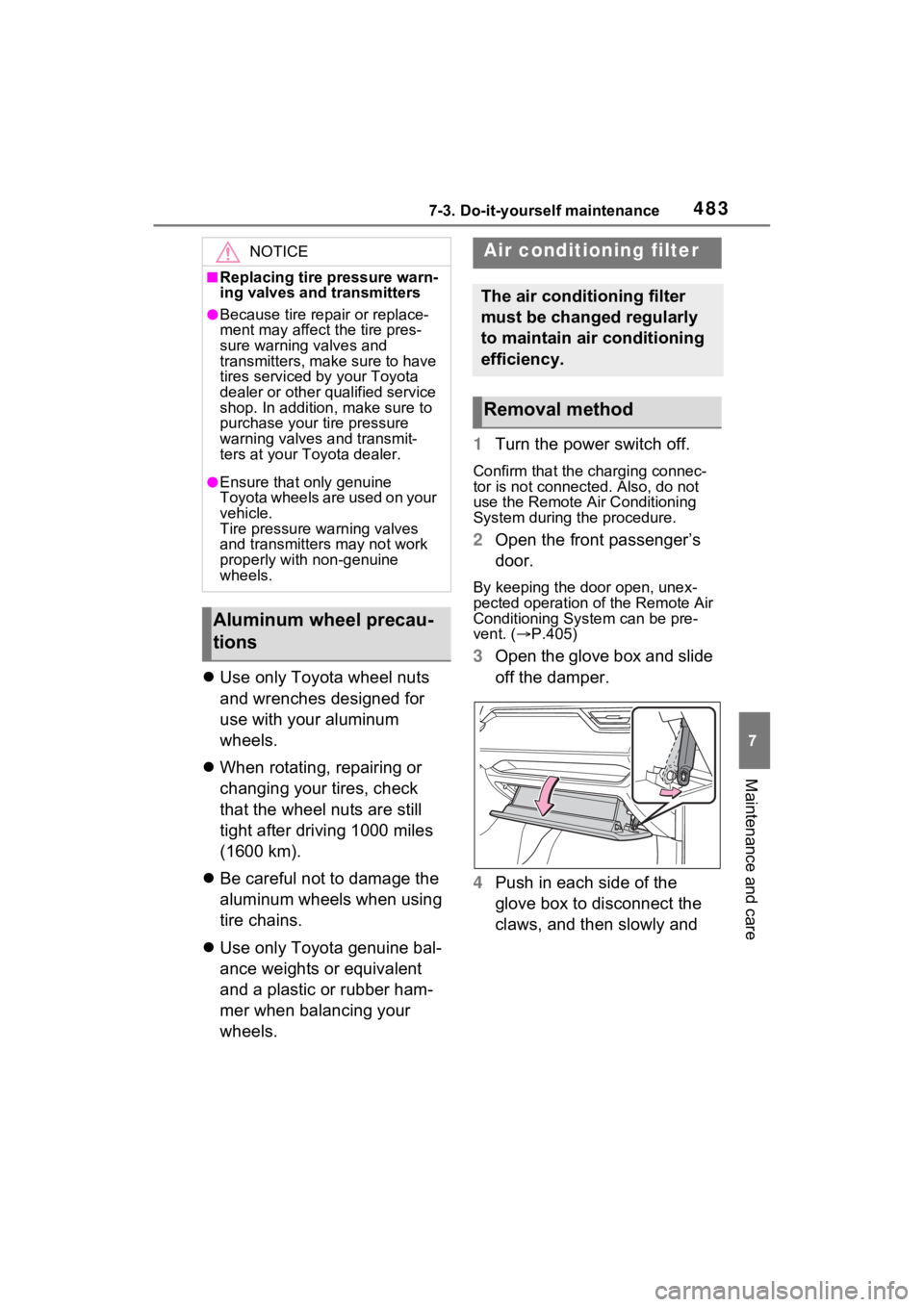
3 Open the glove box and slide
off the damper.
4 Push in each side of the
glove box to disconnect the
claws, and then slowly and
NOTICE
■Replacing tire pressure warn-
ing valves and transmitters
●Because tire repair or replace-
ment may affect the tire pres-
sure warning valves and
transmitters, make sure to have
tires serviced by your Toyota
dealer or other qualified service
shop. In addition, make sure to
purchase your tire pressure
warning valves and transmit-
ters at your Toyota dealer.
●Ensure that only genuine
Toyota wheels are used on your
vehicle.
Tire pressure warning valves
and transmitters may not work
properly with non-genuine
wheels.
Aluminum wheel precau-
tions
Air conditioning filter
The air conditioning filter
must be changed regularly
to maintain air conditioning
efficiency.
Removal method
Page 484 of 618
4847-3. Do-it-yourself maintenance
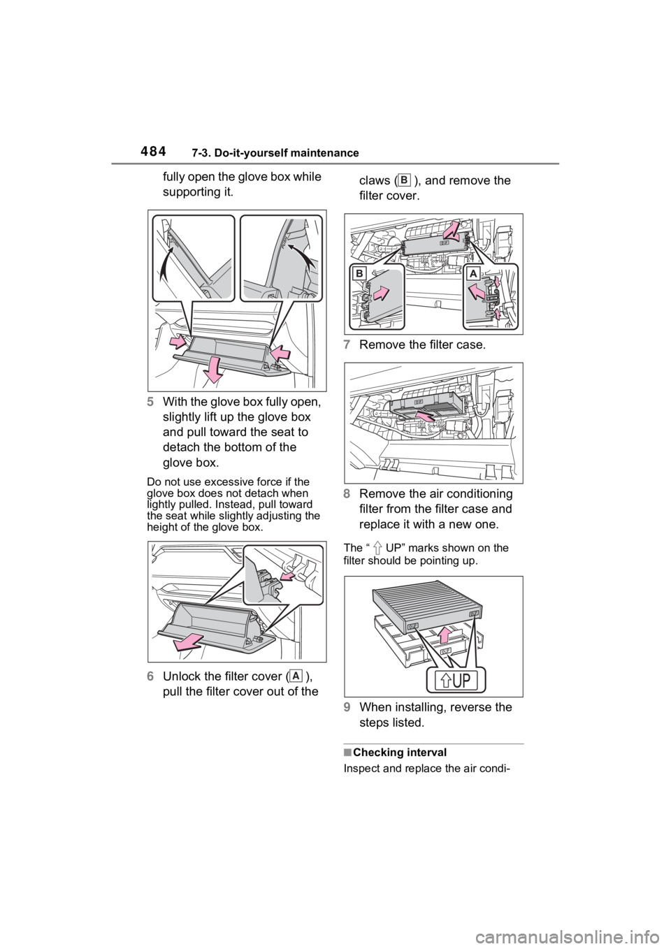
fully open the glove box while
supporting it.
5 With the glove box fully open,
slightly lift up the glove box
and pull toward the seat to
detach the bottom of the
glove box.
Do not use excessive force if the
glove box does not detach when
lightly pulled. Ins tead, pull toward
the seat while slightly adjusting the
height of the glove box.
6 Unlock the filter cover ( ),
pull the filter cover out of the claws ( ), and remove the
filter cover.
7 Remove the filter case.
8 Remove the air conditioning
filter from the filter case and
replace it with a new one.
The “ UP” marks shown on the
filter should be pointing up.
9When installing, reverse the
steps listed.
■Checking interval
Inspect and replace the air condi-
A
B
Page 485 of 618
4857-3. Do-it-yourself maintenance
7
Maintenance and care
tioning filter according to the mainte-
nance schedule. In dusty areas or
areas with heavy traffic flow, early
replacement may be required. (For
scheduled maintenance information,
please refer to the “Owner’s Manual
Supplement” or “Scheduled Mainte-
nance”.)
■If air flow from the vents
decreases dramatically
The filter may be clogged. Check
the filter and replace if necessary.
WARNING
■When replacing the air condi-
tioning filter
Observe the following precau-
tions. Failure to do so may result
in the air conditioning system
operating during the procedure,
possibly resulting in injury.
●Check that the charging con-
nector is not connected
The air conditioning may operate
due to the “Climate Prep”
( P.131) setting.
●Do not use the Remote Air Con-
ditioning System
NOTICE
■When using the air condition-
ing system
Make sure that a filter is always
installed. Using the air condition-
ing system without a filter may
cause damage to the system.
■When removing the glove box
Always follow the specified proce-
dure to remove the glove box
( P.483). If the glove box is
removed without following the
specified procedure, the hinge of
the glove box may become dam-
aged.
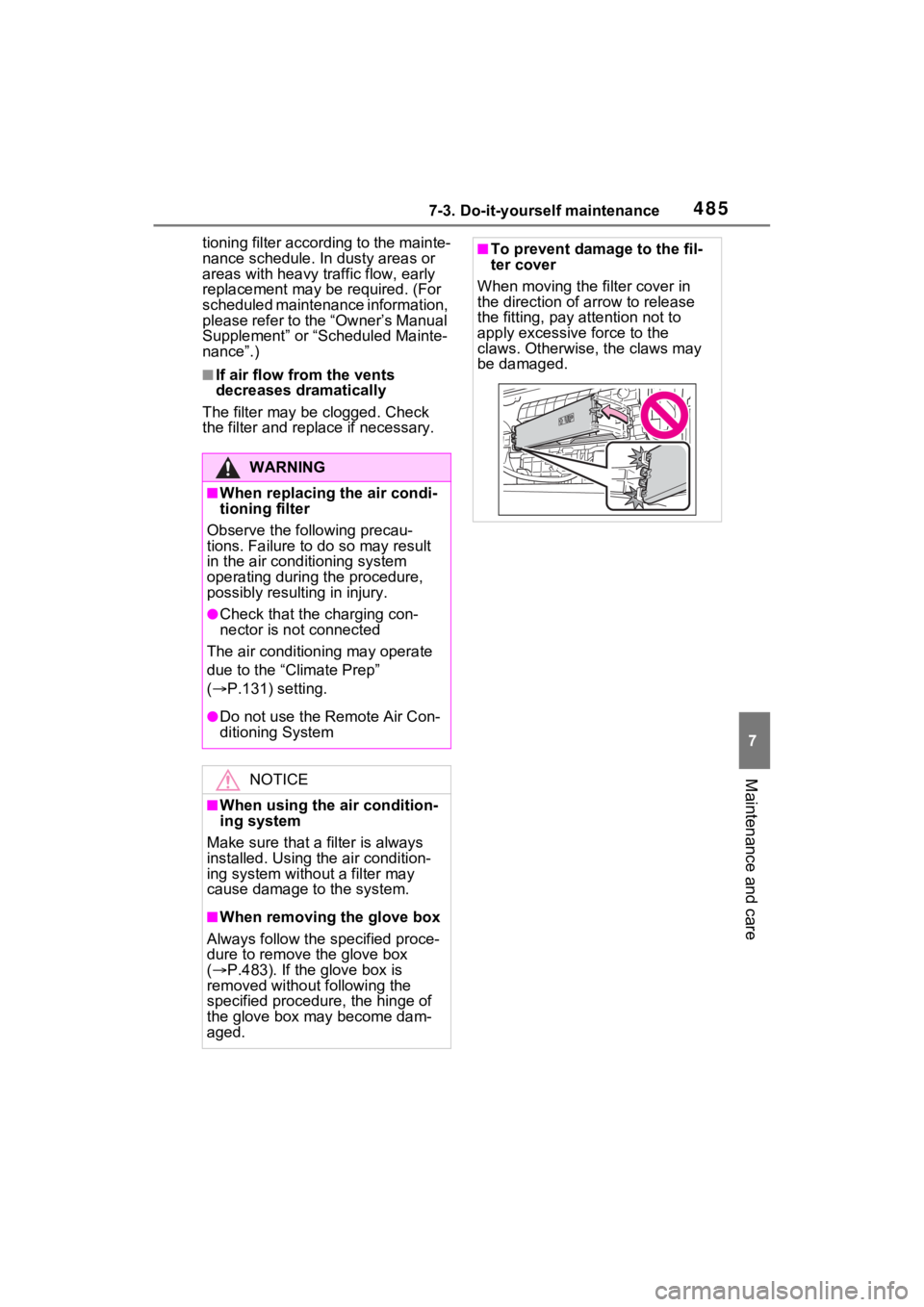
■To prevent damage to the fil-
ter cover
When moving the filter cover in
the direction of arrow to release
the fitting, pay attention not to
apply excessive force to the
claws. Otherwise, the claws may
be damaged.
Page 486 of 618
4867-3. Do-it-yourself maintenance
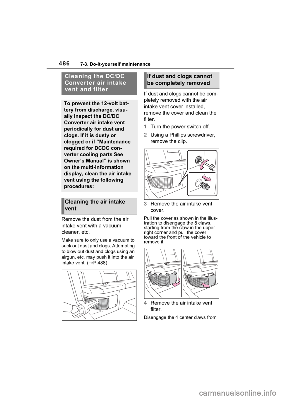
Remove the dust from the air
intake vent with a vacuum
cleaner, etc.
Make sure to only use a vacuum to
suck out dust and clogs. Attempting
to blow out dust and clogs using an
airgun, etc. may push it into the air
intake vent. (P.488)
If dust and clogs cannot be com-
pletely removed with the air
intake vent cover installed,
remove the cover and clean the
filter.
1 Turn the power switch off.
2 Using a Phillips screwdriver,
remove the clip.
3 Remove the air intake vent
cover.
Pull the cover as shown in the illus-
tration to disengage the 8 claws,
starting from the claw in the upper
right corner and pull the cover
toward the front of the vehicle to
remove it.
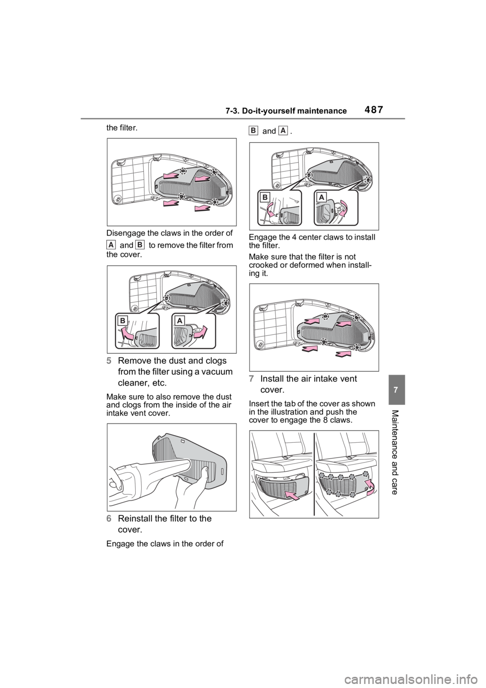
4 Remove the air intake vent
filter.
Disengage the 4 center claws from
Cleaning the DC/DC
Converter air intake
vent and filter
To prevent the 12-volt bat-
tery from discharge, visu-
ally inspect the DC/DC
Converter air intake vent
periodically for dust and
clogs. If it is dusty or
clogged or if “Maintenance
required for DCDC con-
verter cooling parts See
Owner’s Manual” is shown
on the multi-information
display, clean the air intake
vent using the following
procedures:
Cleaning the air intake
vent
If dust and clogs cannot
be completely removed
Page 487 of 618
4877-3. Do-it-yourself maintenance
7
Maintenance and care
the filter.
Disengage the claws in the order of and to remove the filter from
the cover.
5 Remove the dust and clogs
from the filter using a vacuum
cleaner, etc.
Make sure to also remove the dust
and clogs from the inside of the air
intake vent cover.
6Reinstall the filter to the
cover.
Engage the claws in the order of and .
Engage the 4 center claws to install
the filter.
Make sure that the filter is not
crooked or deformed when install-
ing it.
7 Install the air intake vent
cover.
Insert the tab of the cover as shown
in the illustration and push the
cover to enga ge the 8 claws.
AB
BA
Page 488 of 618
4887-3. Do-it-yourself maintenance
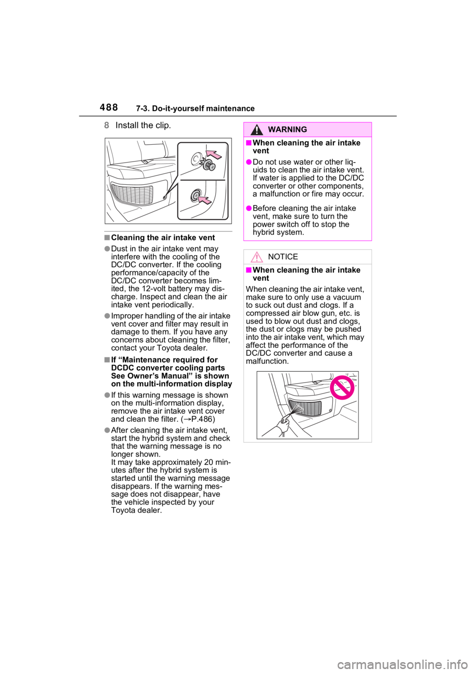
8Install the clip.
■Cleaning the ai r intake vent
●Dust in the air intake vent may
interfere with the cooling of the
DC/DC converter. If the cooling
performance/capacity of the
DC/DC converte r becomes lim-
ited, the 12-volt battery may dis-
charge. Inspect and clean the air
intake vent periodically.
●Improper handling of the air intake
vent cover and filt er may result in
damage to them. If you have any
concerns about cleaning the filter,
contact your Toyota dealer.
■If “Maintenance required for
DCDC converter cooling parts
See Owner’s Manual” is shown
on the multi-information display
●If this warning m essage is shown
on the multi-information display,
remove the air in take vent cover
and clean the filter. ( P.486)
●After cleaning the air intake vent,
start the hybrid system and check
that the warning message is no
longer shown.
It may take approximately 20 min-
utes after the hybrid system is
started until the warning message
disappears. If the warning mes-
sage does not disappear, have
the vehicle inspected by your
Toyota dealer.
WARNING
■When cleaning the air intake
vent
●Do not use water or other liq-
uids to clean the air intake vent.
If water is applied to the DC/DC
converter or other components,
a malfunction or fire may occur.
●Before cleaning the air intake
vent, make sure to turn the
power switch off to stop the
hybrid system.
NOTICE
■When cleaning the air intake
vent
When cleaning the air intake vent,
make sure to onl y use a vacuum
to suck out dust and clogs. If a
compressed air blow gun, etc. is
used to blow out dust and clogs,
the dust or clog s may be pushed
into the air intake vent, which may
affect the perfor mance of the
DC/DC converter and cause a
malfunction.
Page 489 of 618
4897-3. Do-it-yourself maintenance
7
Maintenance and care
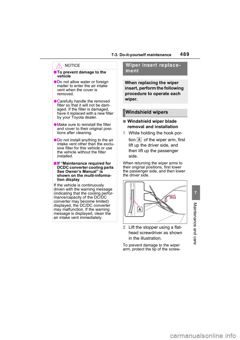
■Windshield wiper blade
removal and installation
1 While holding the hook por-
tion of the wiper arm, first
lift up the driver side, and
then lift up the passenger
side.
When returning the wiper arms to
their original positions, first lower
the passenger side, and then lower
the driver side.
2Lift the stopper using a flat-
head screwdriver as shown
in the illustration.
To prevent damage to the wiper
arm, protect the tip of the screw-
NOTICE
■To prevent damage to the
vehicle
●Do not allow water or foreign
matter to enter t he air intake
vent when the cover is
removed.
●Carefully handle the removed
filter so that i t will not be dam-
aged. If the filter is damaged,
have it replaced with a new filter
by your Toyota dealer.
●Make sure to reinstall the filter
and cover to their original posi-
tions after cleaning.
●Do not install anything to the air
intake vent other than the exclu-
sive filter for this vehicle or use
the vehicle without the filter
installed.
■If “Maintenance required for
DCDC converter cooling parts
See Owner’s Manual” is
shown on the multi-informa-
tion display
If the vehicle is continuously
driven with the warning message
(indicating that the cooling perfor-
mance/capacity of the DC/DC
converter may become limited)
displayed, the DC/DC converter
may malfunction. If the warning
message is displayed, clean the
air intake vent immediately.
Wiper insert replace-
ment
When replacing the wiper
insert, perform the following
procedure to operate each
wiper.
Windshield wipers
A
Page 490 of 618
4907-3. Do-it-yourself maintenance
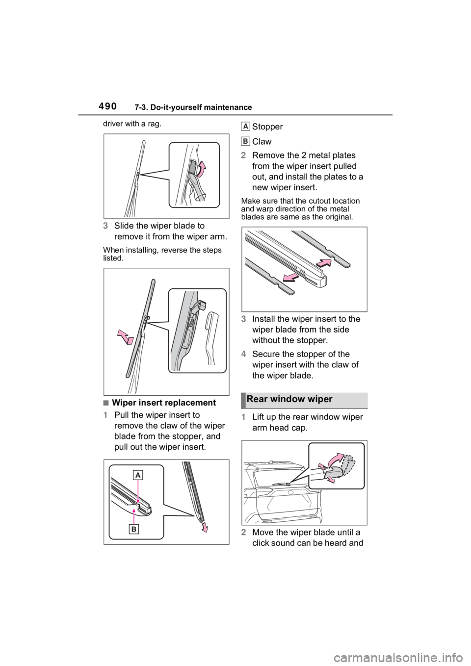
driver with a rag.
3Slide the wiper blade to
remove it from the wiper arm.
When installing, rev erse the steps
listed.
■Wiper insert replacement
1 Pull the wiper insert to
remove the claw of the wiper
blade from the stopper, and
pull out the wiper insert. Stopper
Claw
2 Remove the 2 metal plates
from the wiper insert pulled
out, and install the plates to a
new wiper insert.
Make sure that the cutout location
and warp direction of the metal
blades are same as the original.
3Install the wiper insert to the
wiper blade from the side
without the stopper.
4 Secure the stopper of the
wiper insert with the claw of
the wiper blade.
1 Lift up the rear window wiper
arm head cap.
2 Move the wiper blade until a
click sound can be heard and
Rear window wiper
A
B