air condition TOYOTA SEQUOIA HYBRID 2023 Service Manual
[x] Cancel search | Manufacturer: TOYOTA, Model Year: 2023, Model line: SEQUOIA HYBRID, Model: TOYOTA SEQUOIA HYBRID 2023Pages: 628, PDF Size: 14.27 MB
Page 417 of 628
4175-1. Using the air conditioning system and defogger
Owners Manual_USA_M0C043_en
5
Interior features
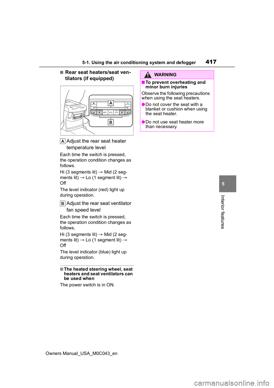
■Rear seat heaters/seat ven-
tilators (if equipped) Adjust the rear seat heater
temperature level
Each time the switch is pressed,
the operation condition changes as
follows.
Hi (3 segments lit) Mid (2 seg-
ments lit) Lo (1 segment lit)
Off
The level indicato r (red) light up
during operation.
Adjust the rear seat ventilator
fan speed level
Each time the switch is pressed,
the operation condition changes as
follows.
Hi (3 segments lit) Mid (2 seg-
ments lit) Lo (1 segment lit)
Off
The level indicator (blue) light up
during operation.
■The heated steering wheel, seat
heaters and seat ventilators can
be used when
The power swit ch is in ON.
WARNING
■To prevent overheating and
minor burn injuries
Observe the following precautions
when using the seat heaters.
●Do not cover the seat with a
blanket or cushion when using
the seat heater.
●Do not use seat heater more
than necessary.
Page 437 of 628
4375-4. Using the other interior features
Owners Manual_USA_M0C043_en
5
Interior features
stable power supply
●Devices that require a constant
power supply from the power out-
let, such as a device with a timer.
■When the power supply func-
tion cannot be used
If the “AC120V” switch is pressed
but the switch indicator does not illu-
minate, the protection circuit may
have operated.
In this case, perform the appropriate
procedures as follows.
●Disconnect the plug of each
device from the p ower outlets,
check that the total power con-
sumption of all devices to be con-
nected to the power outlets,
reconnect the devices and then
press the “AC120V” switch again.
●Disconnect the plug of each
device from the p ower outlets,
check that the devices are not
malfunctioning, reconnect the
devices and then press the
“AC120V” switch again.
●If the temperature inside the vehi-
cle is high, such as after the vehi-
cle has been parked under the
sun, move the vehicle to a shaded
area, use the air conditioning sys-
tem to sufficiently cool the interior,
and then press the “AC120V”
switch again.
If the power outlets cannot be used
even after performing the appropri-
ate procedures above, have the
vehicle inspected by your Toyota
dealer.
●If any electrical device has mal-
functioned, park the vehicle in a
safe location and turn the
“AC120V” switch off.
●If the protection f unction activates
and power is cut, perform the fol-
lowing procedure.
1 Stop the vehicle in a safe place
and set the parking brake.
2 Ensure that the shift lever is in P
or N. 3
Check that the power consumed
by the electrical devices is within
400 W and any device has not
malfunctioned.
4 Press the “AC120V” switch.
If the inside of the vehicle is hot,
open the windows to lower the tem-
perature and turn the switch back on
once the inside of the vehicle
reaches a normal temperature. If
following the procedure above does
not restore power, have the vehicle
inspected at your Toyota dealer.
WARNING
■For safe use
Observe the following precau-
tions.
Failure to do so may lead to an
accident, resulting in death or
serious injury.
●Do not use devices such as the
following when driving:
• Devices which cannot be prop- erly secured within the vehicle.
• Devices which may distract the driver and be a hindrance to
safe driving, such as a TV, DVD
player, etc.
• Unsecured devices which gen- erate heat, such as a toaster,
microwave, electric heater, elec-
tric kettle, coffee maker, etc., as
they may cause burns or a fire
in the case of sudden braking or
an accident.
• Devices which may fall under the pedals and prevent the
brake pedal from being
depressed.
Page 439 of 628
4395-4. Using the other interior features
Owners Manual_USA_M0C043_en
5
Interior features
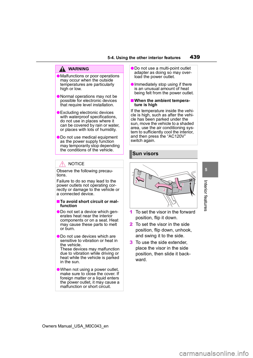
1 To set the visor in the forward
position, flip it down.
2 To set the visor in the side
position, flip down, unhook,
and swing it to the side.
3 To use the side extender,
place the visor in the side
position, then slide it back-
ward.
WARNING
●Malfunctions or poor operations
may occur when the outside
temperatures are particularly
high or low.
●Normal operations may not be
possible for electronic devices
that require level installation.
●Excluding electronic devices
with waterproof specifications,
do not use in places where it
can be covered by rain or water,
or places with lots of humidity.
●Do not use medical equipment
as the power s upply function
may temporarily stop depending
the conditions of the vehicle.
NOTICE
Observe the following precau-
tions.
Failure to do so m ay lead to the
power outlets not operating cor-
rectly or damage to the vehicle or
a connected device.
■To avoid short circuit or mal-
function
●Do not set a device which gen-
erates heat near the interior
components or on a seat. Heat
may cause these parts to melt
or burn.
●Do not use devices which are
sensitive to vibration or heat in
the vehicle.
These devices may malfunction
due to vibration while driving or
heat while the vehicle is parked
in the sun.
●When not using a power outlet,
make sure to close the cover. If
foreign matter or a liquid enters
the power outlet, it may cause a
malfunction or short circuit.
●Do not use a mul ti-point outlet
adapter as doing so may over-
load the power outlet.
●Immediately stop using if there
is an unusual amount of heat
being felt from th e power outlet.
■When the ambient tempera-
ture is high
If the temperature inside the vehi-
cle is high, such as after the vehi-
cle has been parked under the
sun, move the vehicle to a shaded
area, use the air conditioning sys-
tem to sufficiently cool the interior,
and then press the “AC120V”
switch again.
Sun visors
Page 449 of 628
449
Owners Manual_USA_M0C043_en
6
6
Maintenance and care
Maintenance and care
6-1. Maintenance and careCleaning and protecting the vehicle exterior .......... 450
Cleaning and protecting the vehicle interior ........... 453
6-2. Maintenance Maintenance requirements.................................. 456
General maintenance.. 457
Emission inspection and maintenance (I/M) pro-
grams ........................ 460
6-3. Do-it-yourself mainte- nance
Do-it-yourself service pre- cautions ..................... 462
Hood ........................... 464
Engine compartment ... 465
12-volt battery ............. 471
Tires ............................ 474
Tire inflation pressure.. 484
Wheels ......... ...............486
Air conditioning filter .... 487
Cleaning the hybrid battery (traction battery) air intake
vent and filter............. 489
Electronic key battery.. 493
Checking and replacing fuses.......................... 495
Light bulbs................... 498
Page 453 of 628
4536-1. Maintenance and care
Owners Manual_USA_M0C043_en
6
Maintenance and care
Remove dirt and dust using a
vacuum cleaner. Wipe dirty
surfaces with a cloth damp-
ened with lukewarm water.
If dirt cannot be removed,
wipe it off with a soft cloth
dampened with neutral deter-
gent diluted to approximately
1%.
Wring out any excess water
from the cloth and thoroughly
wipe off remaining traces of
detergent and water.
■Shampooing the carpets
There are several commercial foam-
ing-type cleaners available. Use a
sponge or brush to apply the foam.
Rub in overlapping circles. Do not
use water. Wipe dirty surfaces and
let them dry. Excellent results are
obtained by keeping the carpet as
dry as possible.
■Handling the seat belts
Clean with mild soap and lukewarm
water using a cloth or sponge. Also
check the belts periodically for
excessive wear, fraying or cuts.
NOTICE
●Do not spray the lower part of
the windshield continuously.
If water enters the air conditioning
system intake located near the
lower part of the windshield, the
air conditioning system may not
operate correctly.
●Do not wash the underside of
the vehicle usin g a high pres-
sure car washer.
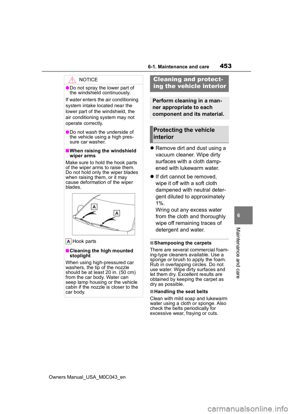
■When raising the windshield
wiper arms
Make sure to hold the hook parts
of the wiper arms to raise them.
Do not hold only the wiper blades
when raising them, or it may
cause deformation of the wiper
blades.
Hook parts
■Cleaning the high mounted
stoplight
When using high-pressured car
washers, the tip of the nozzle
should be at least 20 in. (50 cm)
from the car body. Water can
seep lamp housing or the vehicle
cabin if the nozzle is closer to the
car body.
Cleaning and protect-
ing the vehicle interior
Perform cleaning in a man-
ner appropriate to each
component and its material.
Protecting the vehicle
interior
Page 474 of 628
4746-3. Do-it-yourself maintenance
Owners Manual_USA_M0C043_en
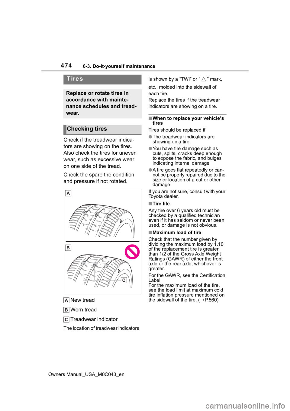
Check if the treadwear indica-
tors are showing on the tires.
Also check the tires for uneven
wear, such as excessive wear
on one side of the tread.
Check the spare tire condition
and pressure if not rotated.
New tread
Worn tread
Treadwear indicator
The location of treadwear indicators is shown by a “TWI” or “ ” mark,
etc., molded into the sidewall of
each tire.
Replace the tires if the treadwear
indicators are s
howing on a tire.
■When to replace your vehicle’s
tires
Tires should be replaced if:
●The treadwear indicators are
showing on a tire.
●You have tire damage such as
cuts, splits, cracks deep enough
to expose the fabric, and bulges
indicating internal damage
●A tire goes flat repeatedly or can-
not be properly repaired due to the
size or location of a cut or other
damage
If you are not sure, consult with your
Toyota dealer.
■Tire life
Any tire over 6 years old must be
checked by a qualified technician
even if it has seldom or never been
used, or damage is not obvious.
■Maximum load of tire
Check that the n umber given by
dividing the maximum load by 1.10
of the replacement tire is greater
than 1/2 of the Gross Axle Weight
Ratings (GAWR) of either the front
axle or the rear axle, whichever is
greater.
For the GAWR, see the Certification
Label.
For the maximum load of the tire,
see the load limit at maximum cold
tire inflation pressure mentioned on
the sidewall of the tire. ( P.560)
Tires
Replace or rotate tires in
accordance with mainte-
nance schedules and tread-
wear.
Checking tires
Page 476 of 628
4766-3. Do-it-yourself maintenance
Owners Manual_USA_M0C043_en
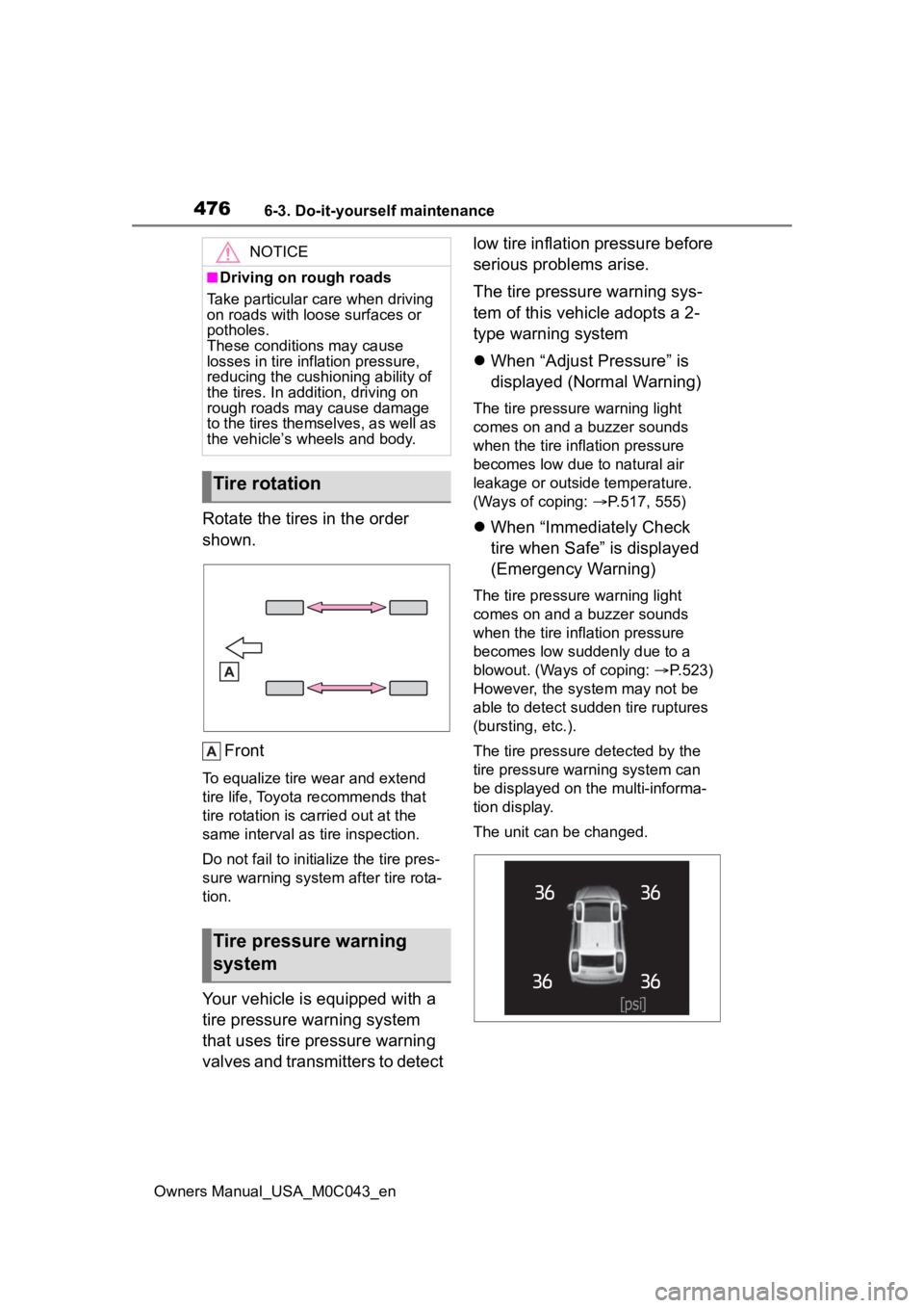
Rotate the tires in the order
shown.
Front
To equalize tire wear and extend
tire life, Toyota recommends that
tire rotation is c arried out at the
same interval as tire inspection.
Do not fail to initialize the tire pres-
sure warning system after tire rota-
tion.
Your vehicle is equipped with a
tire pressure warning system
that uses tire pressure warning
valves and transmitters to detect low tire inflation pressure before
serious problems arise.
The tire pressure warning sys-
tem of this vehicle adopts a 2-
type warning system
When “Adjust Pressure” is
displayed (Normal Warning)
The tire pressure warning light
comes on and a buzzer sounds
when the tire inflation pressure
becomes low due to natural air
leakage or outside temperature.
(Ways of coping: P.517, 555)
When “Immediately Check
tire when Safe” is displayed
(Emergency Warning)
The tire pressure warning light
comes on and a buzzer sounds
when the tire inflation pressure
becomes low suddenly due to a
blowout. (Ways of coping: P.523)
However, the system may not be
able to detect sudden tire ruptures
(bursting, etc.).
The tire pressure detected by the
tire pressure warning system can
be displayed on the multi-informa-
tion display.
The unit can be changed.
NOTICE
■Driving on rough roads
Take particular care when driving
on roads with loose surfaces or
potholes.
These conditions may cause
losses in tire inf lation pressure,
reducing the cushio ning ability of
the tires. In addit ion, driving on
rough roads may cause damage
to the tires themselves, as well as
the vehicle’s wheels and body.
Tire rotation
Tire pressure warning
system
Page 477 of 628
4776-3. Do-it-yourself maintenance
Owners Manual_USA_M0C043_en
6
Maintenance and care
■How to change the unit
1 Park the vehicle in a safe
place and turn the power
switch off.
Changing the unit cannot be per-
formed while the vehicle is moving.
2Turn the power switch to ON.
3 Press or of the meter
control switch to select .
4 Press or to select
“Vehicle Settings” and then
press and hold .
5 Press or to select
“TPWS” and then press .
6 Press or to select “Set
Unit” and then press .
7 Press or to select the
desired unit and then press
.
■Routine tire inflation pressure
checks
The tire pressure warning system
does not replace routine tire inflation
pressure checks. Make sure to
check tire inflation pressure as part
of your routine of daily vehicle
checks.
■Tire inflation pressure
●It may take a few minutes to dis-
play the tire inflation pressure
after the power switch is turned to
ON. It may also take a few min-
utes to display the tire inflation
pressure after inflation pressure
has been adjusted.
●Tire inflation pressure changes
with temperature. The displayed
values may also be different from
the values measured using a tire
pressure gauge.
■Situations in which the tire
pressure warning system may
not operate properly
●In the following cases, the tire
pressure warning system may not
operate properly.
• If non-genuine Toyota wheels are
used.
• A tire has been replaced with a
tire that is not an OE (Original
Equipment) tire.
• A tire has been replaced with a
tire that is not of the specified size.
• Tire chains, etc. , are equipped.
• An auxiliary-support ed run-flat tire
is equipped.
• If a window tint that affects the radio wave signals is installed.
• If there is a lot of snow or ice on
the vehicle, particularly around the
wheels or wheel housings.
• If the tire inflation pressure is
extremely higher than the speci-
fied level.
• If wheels without tire pressure
warning valves and transmitters
are used.
• If the ID code on the tire pressure
warning valves and transmitters is
not registered in the tire pressure
warning computer.
●Performance may be affected in
the following situations.
• Near a TV tower, electric power plant, gas station, radio station,
large display, airpo rt or other facil-
ity that generates strong radio
waves or electrical noise
• When carrying a portable radio,
cellular phone, cordless phone or
other wireless communication
device
If tire position info rmation is not cor-
rectly displayed due to the radio
wave conditions, the display may be
corrected by driving and changing
the radio wave c onditions may
Page 478 of 628
4786-3. Do-it-yourself maintenance
Owners Manual_USA_M0C043_enchange.
●When the vehicle is parked, the
time taken for the warning to start
or go off could be extended.
●When tire inflation pressure
declines rapidly for example when
a tire has burst, the warning may
not function.
■Warning performance of the tire
pressure warning system
The warning of the tire pressure
warning system will change in
accordance with th e conditions
under which it was initialized. For
this reason, the system may give a
warning even if the tire pressure
does not reach a low enough level,
or if the pressure is higher than the
pressure that was adjusted to when
the system was initialized.
■Certification
P. 6 2 5
When replacing tires or wheels,
tire pressure warning valves and
transmitters must also be
installed.
When new tire pressure warning
valves and transmitters are
installed, new ID codes must be
registered in the tire pressure
warning computer and the tire
pressure warning system must
be initialized. ( P.480)
■When replacing the tires and
wheels
If the ID code of the tire pressure
warning valve and transmitter is not
registered, the tire pressure warning
system will not work properly. After driving for about 20 minutes, the tire
pressure warning light blinks for 1
minute and stays on to indicate a
system malfunction.
■The tire pressure warning
system must be initialized
in the following circum-
stances:
When rotating the tires.
When changing the tires.
After registering the ID codes.
( P.480)
When changing between two
registered wheel sets.
When the tire pressure warning
Installing tire pressure
warning valves and trans-
mitters
NOTICE
■Repairing or replacing tires,
wheels, tire pressure warn-
ing valves, transmitters and
tire valve caps
●When removing or fitting the
wheels, tires or the tire pressure
warning valves and transmit-
ters, contact your Toyota dealer
as the tire pressure warning
valves and transmitters may be
damaged if not handled cor-
rectly.
●Make sure to install the tire
valve caps. If the tire valve caps
are not installed, water could
enter the tire pressure warning
valves, corrode the valves and
the tire pressure warning valves
could be bound.
●When replacing tire valve caps,
do not use tire valve caps other
than those specified. The cap
may become stuck.
Initializing the tire pres-
sure warning system
Page 485 of 628
4856-3. Do-it-yourself maintenance
Owners Manual_USA_M0C043_en
6
Maintenance and care
■Instructions for checking tire
inflation pressure
When checking tire inflation pres-
sure, observe the following:
●Check only when the tires are
cold.
If your vehicle has been parked for
at least 3 hours or has not been
driven for more tha n 1 mile or 1.5
km, you will get an accurate cold
tire inflation pressure reading.
●Always use a tire pressure gauge.
It is difficult to judge if a tire is
properly inflated based only on its
appearance.
●It is normal for the tire inflation
pressure to be higher after driving
as heat is generated in the tire. Do
not reduce tire inflation pressure
after driving.
●Never exceed the vehicle capacity
weight.
Passengers and luggage weight
should be placed so that the vehi-
cle is balanced.
WARNING
■Proper inflation is critical to
save tire performance
Keep your tires properly inflated.
If the tires are not properly
inflated, the following conditions
may occur which could lead to an
accident resulting in death or seri-
ous injury:
●Excessive wear
●Uneven wear
●Poor handling
●Possibility of blowouts resulting
from overheated tires
●Air leaking from between tire
and wheel
●Wheel deformation and/or tire
damage
●Greater possibi lity of tire dam-
age while driving (due to road
hazards, expansion joints,
sharp edges in the road, etc.)
NOTICE
■When inspecting and adjust-
ing tire inflation pressure
Be sure to put the tire valve caps
back on.
If a valve cap is no t installed, dirt
or moisture may get into the valve
and cause an air leak, resulting in
decreased tire inflation pressure.