tow TOYOTA SEQUOIA HYBRID 2023 Manual Online
[x] Cancel search | Manufacturer: TOYOTA, Model Year: 2023, Model line: SEQUOIA HYBRID, Model: TOYOTA SEQUOIA HYBRID 2023Pages: 628, PDF Size: 14.27 MB
Page 381 of 628
3814-5. Using the driving support systems
Owners Manual_USA_M0C043_en
4
Driving
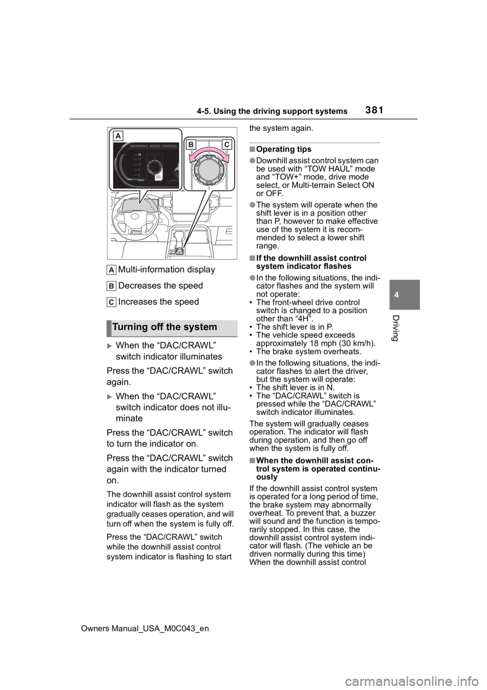
Multi-information display
Decreases the speed
Increases the speed
When the “DAC/CRAWL”
switch indicator illuminates
Press the “DAC/CRAWL” switch
again.
When the “DAC/CRAWL”
switch indicator does not illu-
minate
Press the “DAC/CRAWL” switch
to turn the indicator on.
Press the “DAC/CRAWL” switch
again with the indicator turned
on.
The downhill assist control system
indicator will flash as the system
gradually ceases operation, and will
turn off when the system is fully off.
Press the “DAC/CRAWL” switch
while the downhill assist control
system indicator is flashing to start the system again.
■Operating tips
●Downhill assist con
trol system can
be used with “TOW HAUL” mode
and “TOW+” mode, drive mode
select, or Multi-terrain Select ON
or OFF.
●The system will op erate when the
shift lever is in a position other
than P, however to make effective
use of the system it is recom-
mended to select a lower shift
range.
■If the downhill a ssist control
system indicator flashes
●In the following situ ations, the indi-
cator flashes and the system will
not operate:
• The front-wheel drive control switch is changed to a position
other than “4H”.
• The shift lever is in P.
• The vehicle speed exceeds approximately 18 mph (30 km/h).
• The brake system overheats.
●In the following situ ations, the indi-
cator flashes to alert the driver,
but the system will operate:
• The shift lever is in N.
• The “DAC/CRAWL” switch is pressed while the “DAC/CRAWL”
switch indicator illuminates.
The system will gradually ceases
operation. The indicator will flash
during operation, and then go off
when the system is fully off.
■When the downhill assist con-
trol system is operated continu-
ously
If the downhill assist control system
is operated for a long period of time,
the brake system may abnormally
overheat. To preve nt that, a buzzer
will sound and the function is tempo-
rarily stopped. In this case, the
downhill assist control system indi-
cator will flash. (Th e vehicle an be
driven normally during this time)
When the downhill assist control
Turning off the system
Page 383 of 628

3834-5. Using the driving support systems
Owners Manual_USA_M0C043_en
4
Driving
system detects a panic stop sit-
uation
■Enhanced VSC (Enhanced
Vehicle Stability Control)
Provides cooperative control of
the ABS, TRAC, VSC and EPS.
Helps to maintai n directional
stability when swerving on slip-
pery road surfaces by con-
trolling steering performance.
■Trailer Sway Control
Helps the driver to control trailer
sway by selectively applying
brake pressure for individual
wheels and reducing driving
torque when trailer sway is
detected.
■TRAC (Traction Control)
Helps to maintain drive power
and prevent the drive wheels
from spinning when starting the
vehicle or accelerating on slip-
pery roads
■Hill-start assist control
Helps to reduce the backward
movement of the vehicle when
starting on an uphill
■AVS (Adaptive Variable
Suspension System) (if
equipped)
The damping force of the shock
absorbers are independently
controlled for the 4 wheels
according to factors including
the road surface conditions and
driving operation, contributing
toward enhancing smooth driv- ing comfort and superior stabil-
ity, and helping to maintain
vehicle posture.
In addition, the damping force
can be changed by selecting the
drive mode with the driving
mode select (
P.366), and driv-
ing comfort can be ensured
during off-road driving by setting
the front-wheel drive control
switch to “4L”.( P.369)
■EPS (Electric Power Steer-
ing)
Employs an electric motor to
reduce the amount of effort
needed to turn the steering
wheel
■The Secondary Collision
Brake
When the SRS airbag sensor
detects a collision and the sys-
tem operates, the brakes and
brake lights are automatically
controlled to reduce the vehicle
speed and help reduce the pos-
sibility of further damage due to
a secondary collision.
■When the
TRAC/VSC/ABS/Trailer Sway
Control systems are operating
The slip indicator light will flash
while the TRAC/VSC/ABS/Trailer
Sway Control systems are operat-
ing.
Page 387 of 628
3874-5. Using the driving support systems
Owners Manual_USA_M0C043_en
4
Driving
WARNING
■Replacing tires
Make sure that all tires are of the
specified size, brand, tread pat-
tern and total load capacity. In
addition, make sure that the tires
are inflated to the recommended
tire inflation pressure level.
The ABS, TRAC, Trailer Sway
Control and VSC systems will not
function correctly if different tires
are installed on the vehicle.
Contact your Toyota dealer for fur-
ther information when replacing
tires or wheels.
■Handling of tires and the sus-
pension
Using tires with any kind of prob-
lem or modifying the suspension
will affect the driving assist sys-
tems, and may cause a system to
malfunction.
■Trailer Sway Control precau-
tion
The Trailer Sway Control system
is not able to reduce trailer sway
in all situations . Depending on
many factors such as the condi-
tions of the vehicle, trailer, road
surface and driving environment,
the Trailer Sway Control system
may not be effec tive. Refer to
your trailer owner’s manual for
information on how to tow your
trailer properly.
■If trailer sway occurs
Observe the following precau-
tions.
Failing to do so may cause death
or serious injury.
●Firmly grip the steering wheel.
Steer straight ahead. Do not try
to control trailer sway by turning
the steering wheel.
●Begin releasing the accelerator
pedal immediately but very
gradually to reduce speed.
Do not increase speed. Do not
apply vehicle brakes.
If you make no extreme correction
with the steering or brakes, your
vehicle and traile r should stabi-
lize. ( P.198)
■Secondary Collision Brake
Do not rely solely upon the Sec-
ondary Collision Brake. This sys-
tem is designed to help reduce
the possibility of further damage
due to a secondary collision, how-
ever, that effect changes accord-
ing to various conditions. Overly
relying on the system may result
in death or serious injury.
Page 389 of 628
3894-5. Using the driving support systems
Owners Manual_USA_M0C043_en
4
Driving
Select the item desired to be
setup and select as follows on
the multi-information screen
( P.102):
1 Press or on the meter
control switch and then select
.
2 Press or on the meter
control switch, select “Trailer
Settings”, and then press and
hold on the meter control
switch.
3 According to the display,
select the desired setting and
then press .
Changing trailer brake type or
trailer ID will cause the current
“gain” setting to reset to zero.
Make sure to set the “gain” as
described in the following sec-
tion.
“Gain” setting on trailer brake
controller should be set for a
specific towing condition. “Gain”
setting should be adjusted each
time the vehicle load, trailer
load, road conditions, or
weather changes. Setting the
“gain” value to 0 will disable the
trailer brake controller output. 1
Make sure the trailer brakes
are in good working condition
and functioning normally. See
trailer dealer if necessary.
2 Hook up the trailer and make
proper electrical connections.
3 Select the correct type of
trailer brakes that are
equipped on the trailer by
using the multi-information
display.
4 Drive vehicle with trailer
attached on a level road sur-
face similar to towing condi-
tion and in traffic-free
environment. Driving speed
should be approximately 20 -
25 mph [35 - 40 km/h].
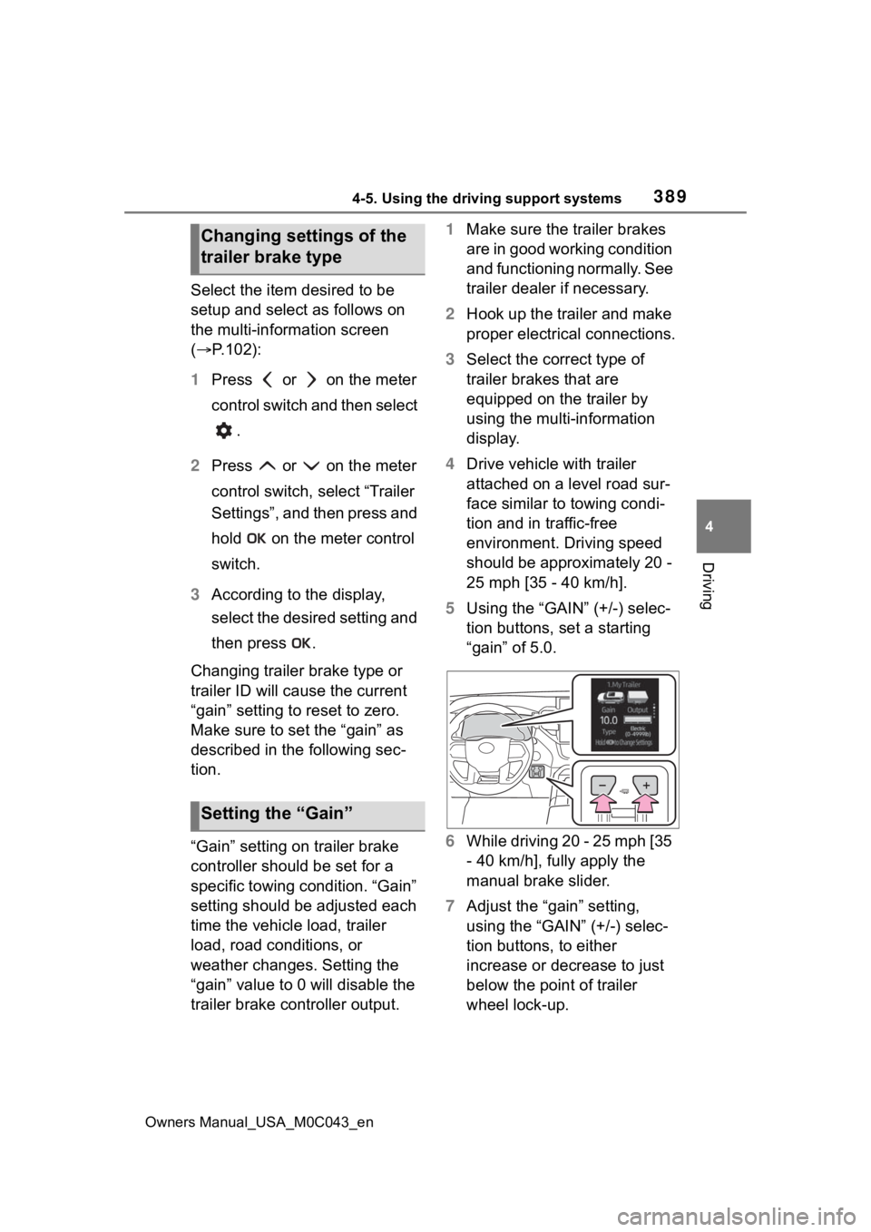
5 Using the “GAIN” (+/-) selec-
tion buttons, set a starting
“gain” of 5.0.
6 While driving 20 - 25 mph [35
- 40 km/h], fully apply the
manual brake slider.
7 Adjust the “gain” setting,
using the “GAIN” (+/-) selec-
tion buttons, to either
increase or decrease to just
below the point of trailer
wheel lock-up.
Changing settings of the
trailer brake type
Setting the “Gain”
Page 390 of 628
3904-5. Using the driving support systems
Owners Manual_USA_M0C043_en
8For confirmation, repeat
steps 6 and 7 until desired
“gain” setting is reached (just
below point of trailer wheel
lock-up).
■When setting the “gain”
Wheel lock-up occurs when the
trailer wheel squeals or tire smoke
occurs. Trailer wheels may not lock-
up while driving heavily loaded
trailer. During this case, adjust the
Trailer “gain” to the highest allow-
able setting for the towing condition.
■When disconnecting and recon-
necting 12-volt battery termi-
nals
The “gain” setting data will be reset.
■Trailer Sway Control Function
Helps suppress trailer sway at an
early stage by using the trailer brake
control system to operate the trailer
brakes.
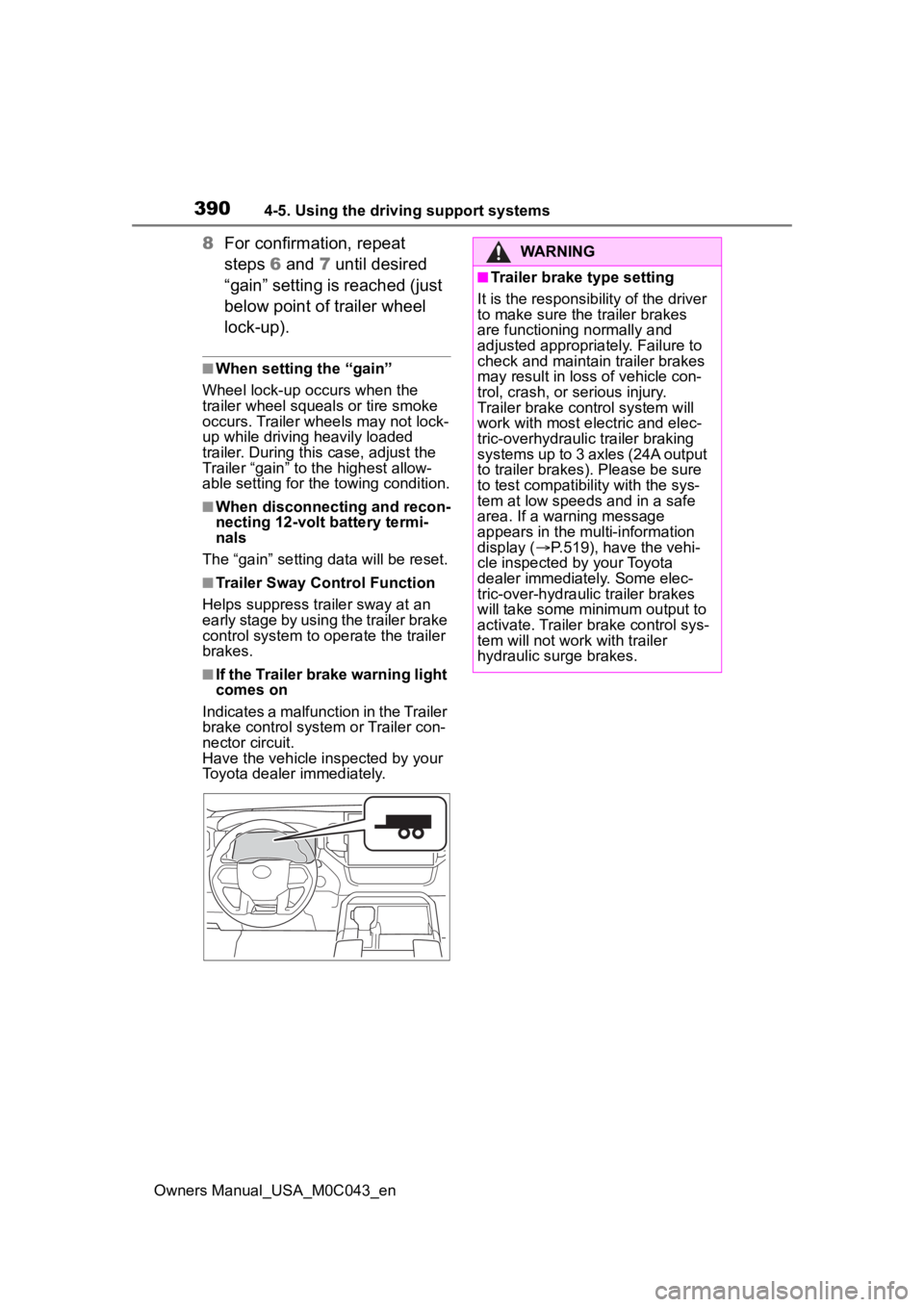
■If the Trailer brake warning light
comes on
Indicates a malfunction in the Trailer
brake control system or Trailer con-
nector circuit.
Have the vehicle inspected by your
Toyota dealer immediately.
WARNING
■Trailer brake type setting
It is the responsibility of the driver
to make sure the trailer brakes
are functioning normally and
adjusted appropriately. Failure to
check and maintain trailer brakes
may result in loss of vehicle con-
trol, crash, or serious injury.
Trailer brake control system will
work with most electric and elec-
tric-overhydraulic trailer braking
systems up to 3 axles (24A output
to trailer brakes). Please be sure
to test compatibility with the sys-
tem at low speeds and in a safe
area. If a warning message
appears in the multi-information
display ( P.519), have the vehi-
cle inspected by your Toyota
dealer immediately. Some elec-
tric-over-hydraulic trailer brakes
will take some minimum output to
activate. Trailer brake control sys-
tem will not work with trailer
hydraulic surge brakes.
Page 424 of 628
4245-3. Using the storage features
Owners Manual_USA_M0C043_en
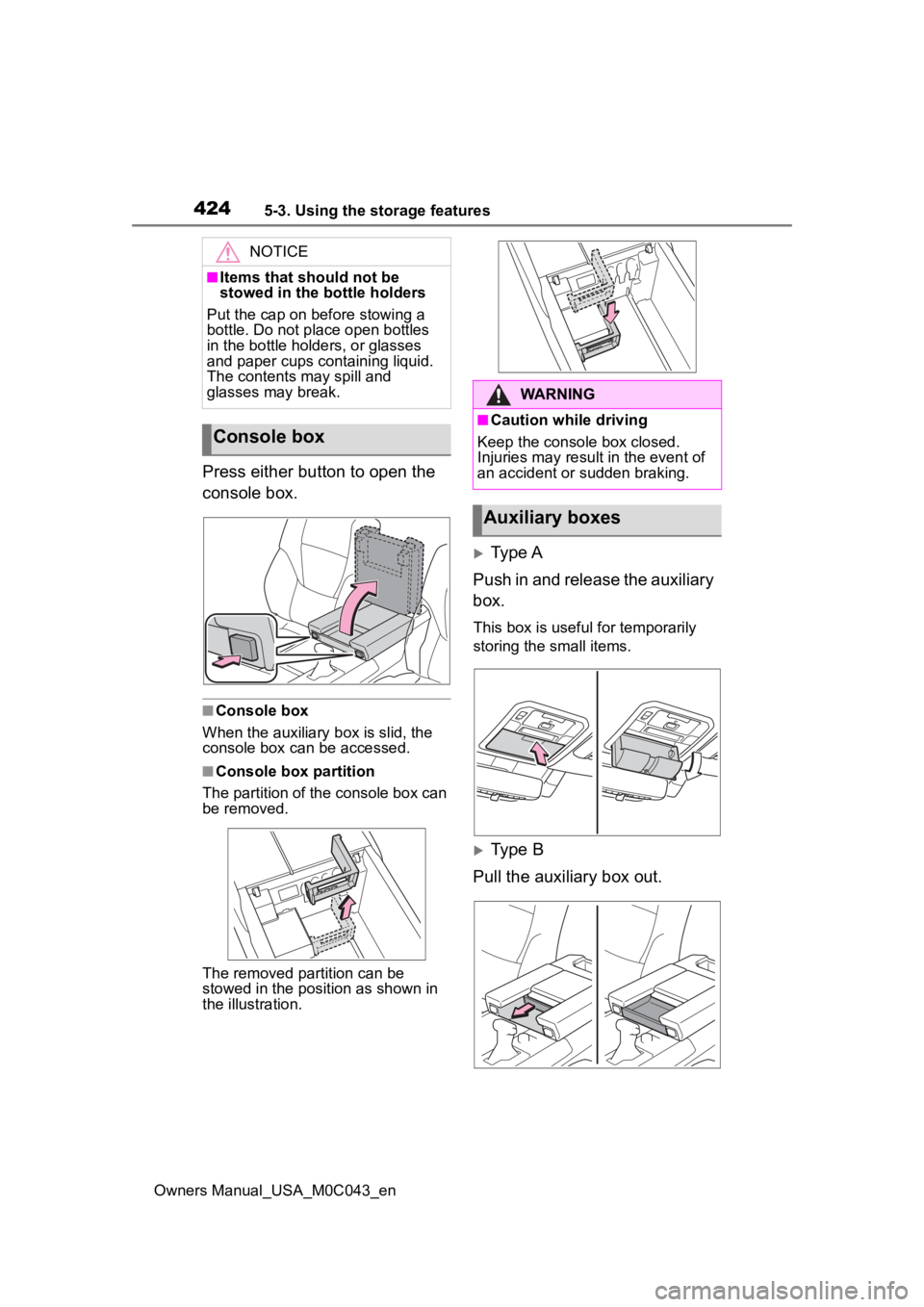
Press either button to open the
console box.
■Console box
When the auxiliary b ox is slid, the
console box can be accessed.
■Console box partition
The partition of the console box can
be removed.
The removed partition can be
stowed in the posit ion as shown in
the illustration.
Type A
Push in and release the auxiliary
box.
This box is useful for temporarily
storing the small items.
Type B
Pull the auxiliary box out.
NOTICE
■Items that should not be
stowed in the bottle holders
Put the cap on before stowing a
bottle. Do not place open bottles
in the bottle holders, or glasses
and paper cups containing liquid.
The contents may spill and
glasses may break.
Console box
WARNING
■Caution while driving
Keep the console box closed.
Injuries may resul t in the event of
an accident or sudden braking.
Auxiliary boxes
Page 426 of 628
4265-3. Using the storage features
Owners Manual_USA_M0C043_en
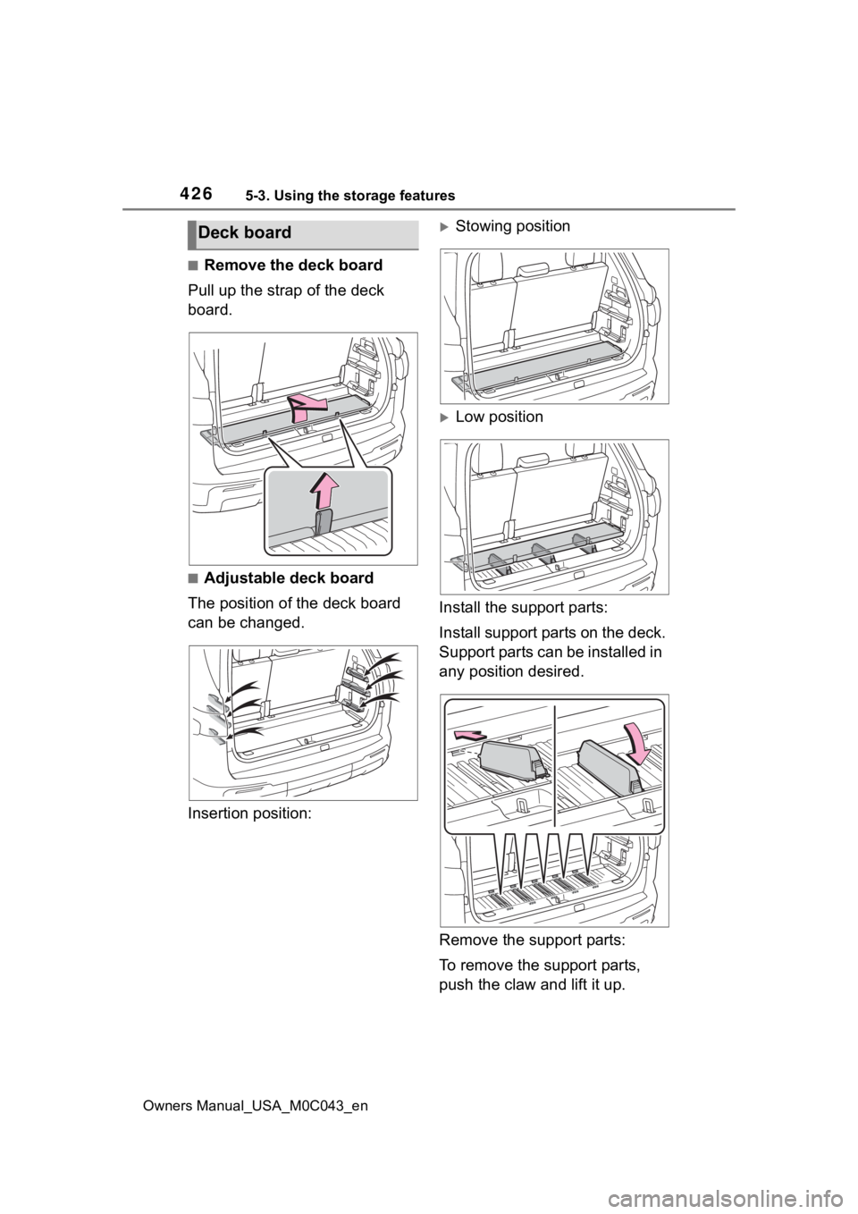
■Remove the deck board
Pull up the strap of the deck
board.
■Adjustable deck board
The position of the deck board
can be changed.
Insertion position:
Stowing position
Low position
Install the support parts:
Install support parts on the deck.
Support parts can be installed in
any position desired.
Remove the support parts:
To remove the support parts,
push the claw and lift it up.
Deck board
Page 432 of 628
4325-4. Using the other interior features
Owners Manual_USA_M0C043_en
WARNING
■Caution regarding interfer-
ence with electronic devices
People with implantable cardiac
pacemakers, cardiac resynchroni-
zation therapy-pacemakers or
implantable cardioverter defibrilla-
tors, as well as any other electri-
cal medical device, should consult
their physician about the usage of
the wireless charger. The opera-
tions of the wireless charger may
have an affect on medical
devices.
■To prevent damage or burns
Observe the following precau-
tions.
Failure to do so m ay result in a
possibility of equ ipment failure
and damage, catch fire, burns due
to overheat.
●Do not insert any metallic
objects between the charging
area and the portable device
while charging
●Do not attach stickers, metallic
objects, etc., to the charger area
or portable device
●Do not cover with cloth, etc.,
and charge
●Do not charge portable devices
other than designated
●Do not attempt t o dismantle for
disassembly or modifications
●Do not hit or apply a strong
force
NOTICE
■Conditions in which the func-
tion may not operate cor-
rectly
In the following co nditions, it may
not operate correctly
●The portable device is fully
charged
●There is foreign matter between
the charge area and portable
device
●The temperature of the portable
device gets higher from
charging
●The charging surface of the por-
table device is facing up
●The placement of the portable
device is out of alignment with
the charge area
●Near a TV tower, electric power
plant, gas station, radio station,
large display, a irport or other
facility that gen erates strong
radio waves or electrical noise
●When the portable device is in
contact with, or is covered by
the following metallic objects
• Cards to which aluminum foil is attached
• Cigarette boxes that have alu- minum foil inside
• Metallic wallets or bags
• Coins
• Hand warmers made of metal
• Media such as CDs and DVDs
Page 462 of 628
4626-3. Do-it-yourself maintenance
Owners Manual_USA_M0C043_en
6-3.Do-it-yourself maintenance
Do-it-yourself ser vice
precautions
If you perform maintenance
by yourself, be sure to fol-
low the correct procedure
as given in these sections.
Maintenance
ItemsParts and tools
12-volt battery
condition
( P.471)
•Grease
•Warm water
• Baking soda
• Distilled water
• Conventional
wrench (for ter-
minal clamp
bolts)
Brake fluid
level ( P.469)
• FMVSS No.116
DOT 3 or SAE
J1703 brake fluid
FMVSS No.116
DOT 4 or SAE
J1704 brake fluid
• Rag or paper towel
• Funnel (used only for adding
brake fluid)
Engine/inter-
cooler/power
control unit
coolant level
( P.468)
• “Toyota Super
Long Life Cool-
ant” or a similar
high quality eth-
ylene glycol-
based non-sili-
cate, non-amine,
non-nitrite and
non-borate cool-
ant with longlife
hybrid organic
acid technology
For the U.S.A.:
“Toyota Super
Long Life Cool-
ant” is pre-mixed
with 50% cool-
ant and 50%
deionized water.
For Canada:
“Toyota Super
Long Life Cool-
ant” is pre-mixed
with 55% cool-
ant and 45%
deionized water.
• Funnel (used only for adding
coolant)
Engine oil level
( P.466)
• “Toyota Genuine
Motor Oil” or
equivalent
• Rag or paper towel
• Funnel (used only for adding
engine oil)
Fuses
( P.495)• Fuse with same
amperage rating
as original
ItemsParts and tools
Page 466 of 628
4666-3. Do-it-yourself maintenance
Owners Manual_USA_M0C043_en
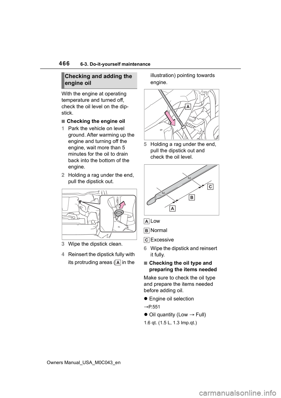
With the engine at operating
temperature and turned off,
check the oil level on the dip-
stick.
■Checking the engine oil
1 Park the vehicle on level
ground. After warming up the
engine and turning off the
engine, wait more than 5
minutes for the oil to drain
back into the bottom of the
engine.
2 Holding a rag under the end,
pull the dipstick out.
3 Wipe the dipstick clean.
4 Reinsert the dipstick fully with
its protruding areas ( in the illustration) pointing towards
engine.
5 Holding a rag under the end,
pull the dipstick out and
check the oil level.
Low
Normal
Excessive
6 Wipe the dipstick and reinsert
it fully.
■Checking the oil type and
preparing the items needed
Make sure to check the oil type
and prepare the items needed
before adding oil.
Engine oil selection
P.551
Oil quantity (Low Full)
1.6 qt. (1.5 L, 1.3 Imp.qt.)
Checking and adding the
engine oil