TOYOTA SIENNA 2007 Service Repair Manual
Manufacturer: TOYOTA, Model Year: 2007, Model line: SIENNA, Model: TOYOTA SIENNA 2007Pages: 3000, PDF Size: 52.26 MB
Page 1371 of 3000
CH–222GR-FE CHARGING – GENERATOR
CH
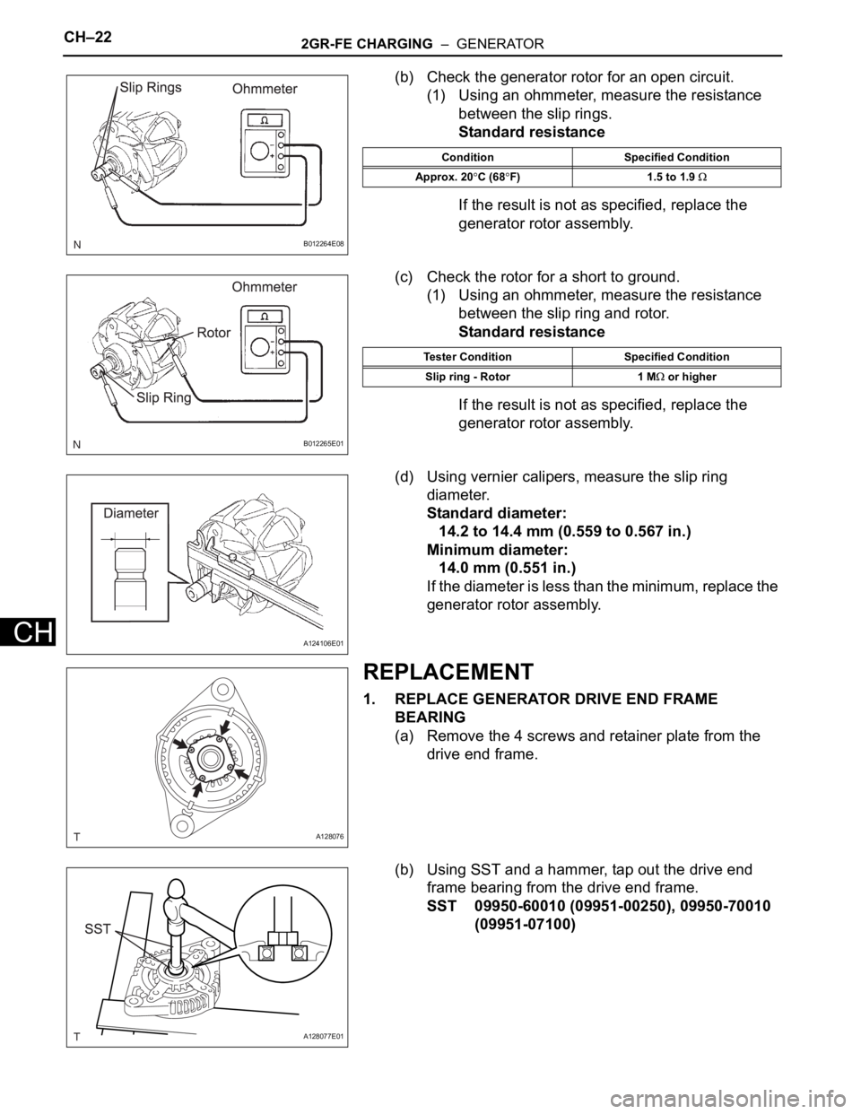
(b) Check the generator rotor for an open circuit.
(1) Using an ohmmeter, measure the resistance
between the slip rings.
Standard resistance
If the result is not as specified, replace the
generator rotor assembly.
(c) Check the rotor for a short to ground.
(1) Using an ohmmeter, measure the resistance
between the slip ring and rotor.
Standard resistance
If the result is not as specified, replace the
generator rotor assembly.
(d) Using vernier calipers, measure the slip ring
diameter.
Standard diameter:
14.2 to 14.4 mm (0.559 to 0.567 in.)
Minimum diameter:
14.0 mm (0.551 in.)
If the diameter is less than the minimum, replace the
generator rotor assembly.
REPLACEMENT
1. REPLACE GENERATOR DRIVE END FRAME
BEARING
(a) Remove the 4 screws and retainer plate from the
drive end frame.
(b) Using SST and a hammer, tap out the drive end
frame bearing from the drive end frame.
SST 09950-60010 (09951-00250), 09950-70010
(09951-07100)
B012264E08
Condition Specified Condition
Approx. 20
C (68F) 1.5 to 1.9
B012265E01
Tester Condition Specified Condition
Slip ring - Rotor 1 M
or higher
A124106E01
A128076
A128077E01
Page 1372 of 3000
2GR-FE CHARGING – GENERATORCH–23
CH
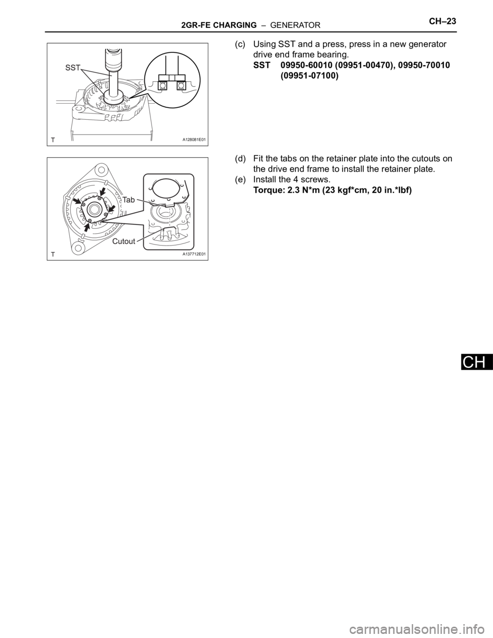
(c) Using SST and a press, press in a new generator
drive end frame bearing.
SST 09950-60010 (09951-00470), 09950-70010
(09951-07100)
(d) Fit the tabs on the retainer plate into the cutouts on
the drive end frame to install the retainer plate.
(e) Install the 4 screws.
Torque: 2.3 N*m (23 kgf*cm, 20 in.*lbf)
A128081E01
A137712E01
Page 1373 of 3000
CH–242GR-FE CHARGING – GENERATOR
CH
REASSEMBLY
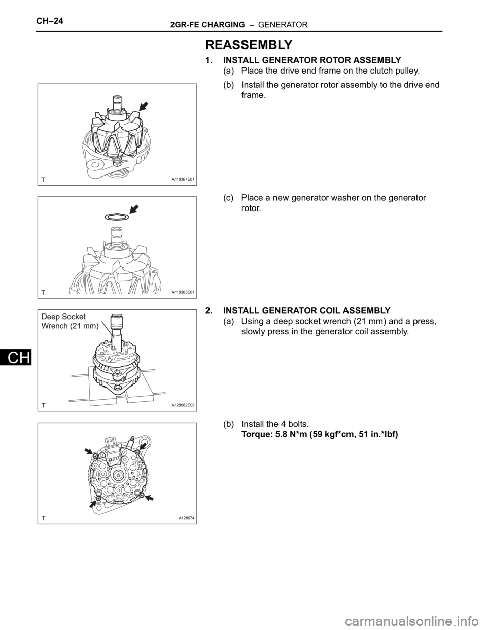
1. INSTALL GENERATOR ROTOR ASSEMBLY
(a) Place the drive end frame on the clutch pulley.
(b) Install the generator rotor assembly to the drive end
frame.
(c) Place a new generator washer on the generator
rotor.
2. INSTALL GENERATOR COIL ASSEMBLY
(a) Using a deep socket wrench (21 mm) and a press,
slowly press in the generator coil assembly.
(b) Install the 4 bolts.
Torque: 5.8 N*m (59 kgf*cm, 51 in.*lbf)
A118367E01
A118365E01
A128082E03
A128074
Page 1374 of 3000
2GR-FE CHARGING – GENERATORCH–25
CH
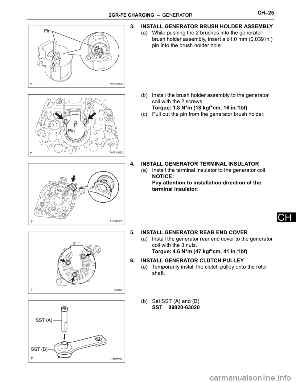
3. INSTALL GENERATOR BRUSH HOLDER ASSEMBLY
(a) While pushing the 2 brushes into the generator
brush holder assembly, insert a
1.0 mm (0.039 in.)
pin into the brush holder hole.
(b) Install the brush holder assembly to the generator
coil with the 2 screws.
Torque: 1.8 N*m (18 kgf*cm, 16 in.*lbf)
(c) Pull out the pin from the generator brush holder.
4. INSTALL GENERATOR TERMINAL INSULATOR
(a) Install the terminal insulator to the generator coil.
NOTICE:
Pay attention to installation direction of the
terminal insulator.
5. INSTALL GENERATOR REAR END COVER
(a) Install the generator rear end cover to the generator
coil with the 3 nuts.
Torque: 4.6 N*m (47 kgf*cm, 41 in.*lbf)
6. INSTALL GENERATOR CLUTCH PULLEY
(a) Temporarily install the clutch pulley onto the rotor
shaft.
(b) Set SST (A) and (B).
SST 09820-63020
A079315E13
A079316E02
A128083E01
A128071
A128084E01
Page 1375 of 3000
CH–262GR-FE CHARGING – GENERATOR
CH
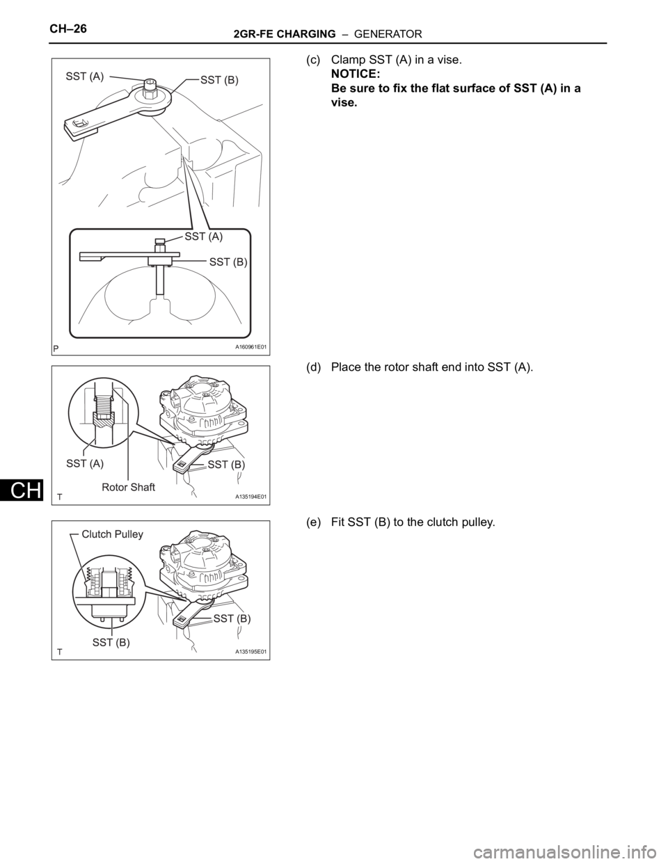
(c) Clamp SST (A) in a vise.
NOTICE:
Be sure to fix the flat surface of SST (A) in a
vise.
(d) Place the rotor shaft end into SST (A).
(e) Fit SST (B) to the clutch pulley.
A160961E01
A135194E01
A135195E01
Page 1376 of 3000
2GR-FE CHARGING – GENERATORCH–27
CH
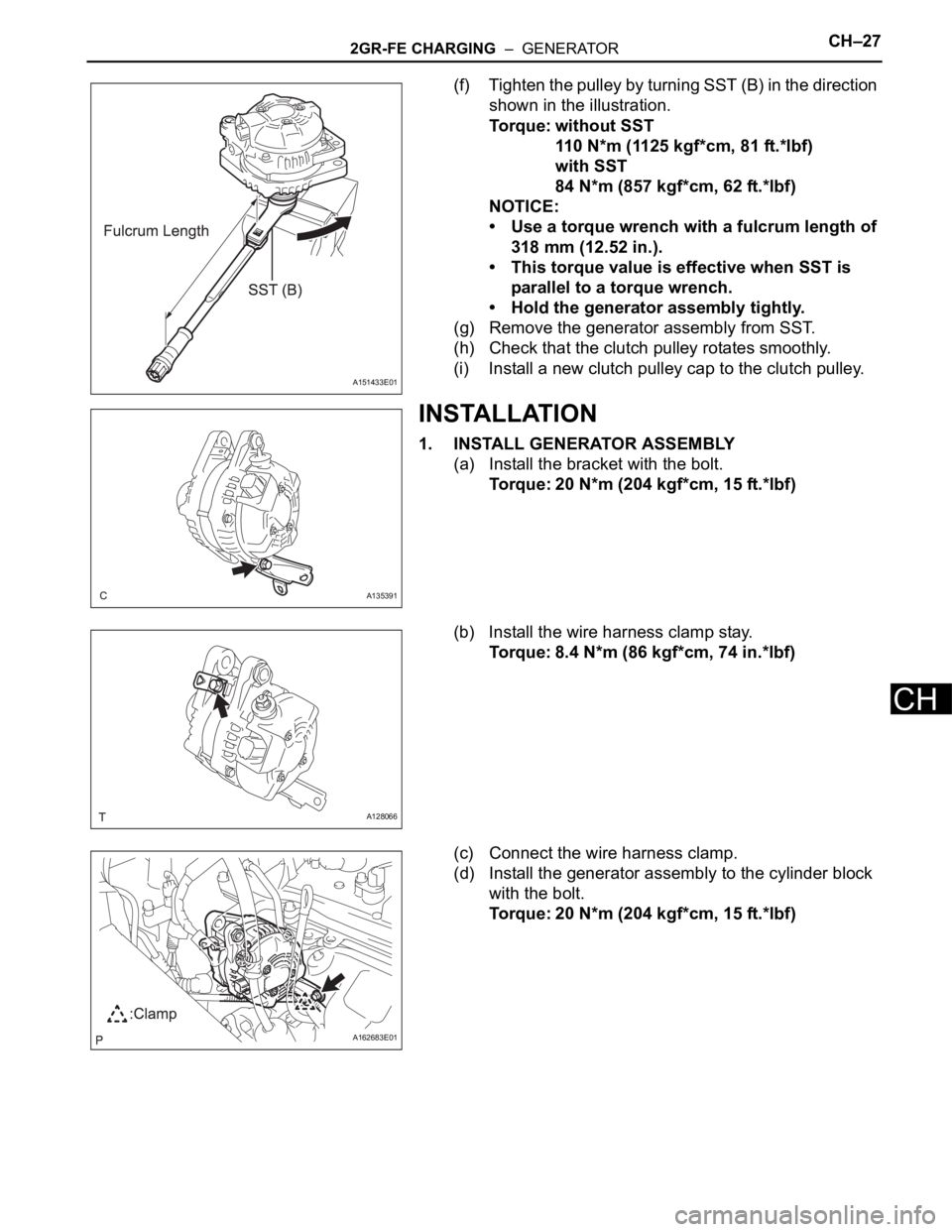
(f) Tighten the pulley by turning SST (B) in the direction
shown in the illustration.
Torque: without SST
110 N*m (1125 kgf*cm, 81 ft.*lbf)
with SST
84 N*m (857 kgf*cm, 62 ft.*lbf)
NOTICE:
• Use a torque wrench with a fulcrum length of
318 mm (12.52 in.).
• This torque value is effective when SST is
parallel to a torque wrench.
• Hold the generator assembly tightly.
(g) Remove the generator assembly from SST.
(h) Check that the clutch pulley rotates smoothly.
(i) Install a new clutch pulley cap to the clutch pulley.
INSTALLATION
1. INSTALL GENERATOR ASSEMBLY
(a) Install the bracket with the bolt.
Torque: 20 N*m (204 kgf*cm, 15 ft.*lbf)
(b) Install the wire harness clamp stay.
Torque: 8.4 N*m (86 kgf*cm, 74 in.*lbf)
(c) Connect the wire harness clamp.
(d) Install the generator assembly to the cylinder block
with the bolt.
Torque: 20 N*m (204 kgf*cm, 15 ft.*lbf)
A151433E01
A135391
A128066
A162683E01
Page 1377 of 3000
CH–282GR-FE CHARGING – GENERATOR
CH
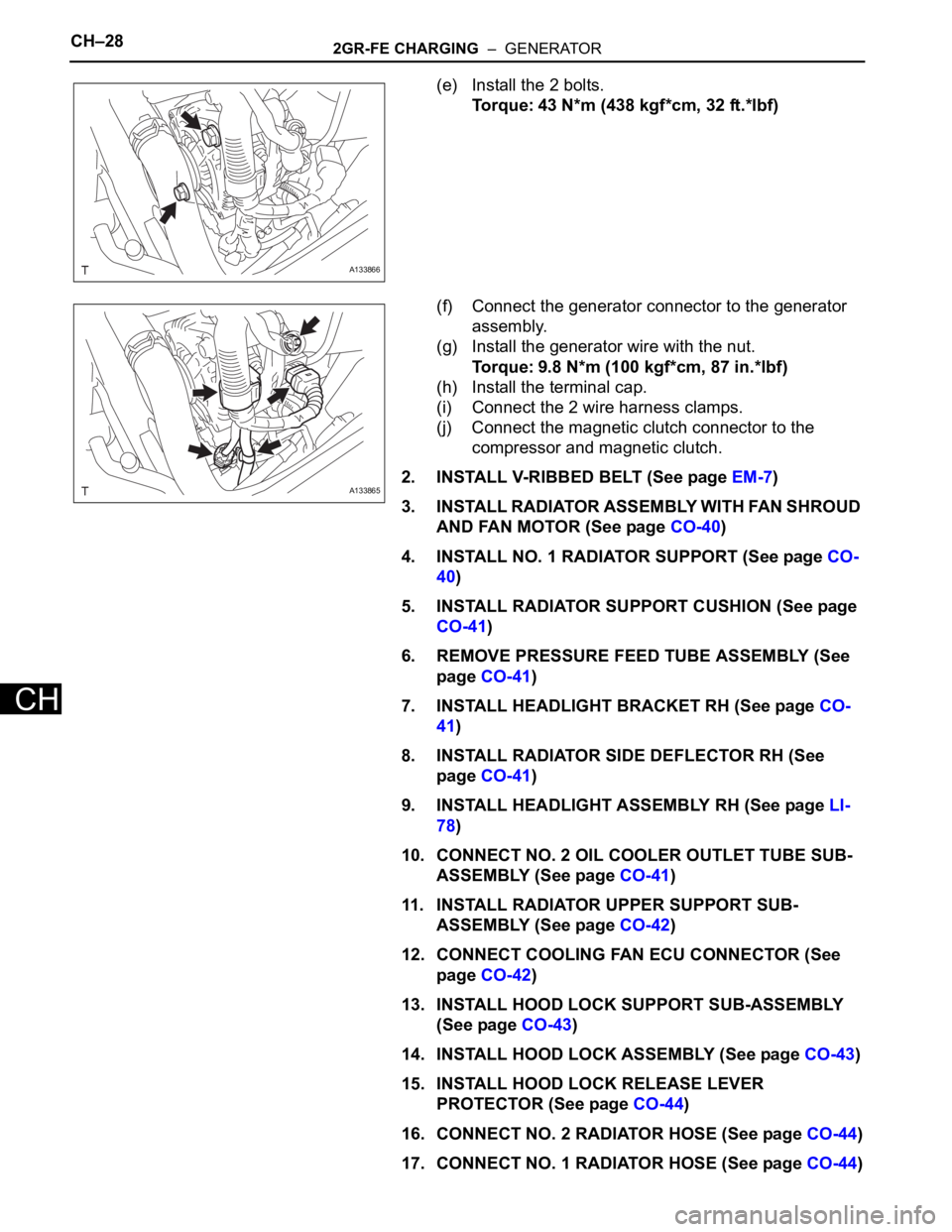
(e) Install the 2 bolts.
Torque: 43 N*m (438 kgf*cm, 32 ft.*lbf)
(f) Connect the generator connector to the generator
assembly.
(g) Install the generator wire with the nut.
Torque: 9.8 N*m (100 kgf*cm, 87 in.*lbf)
(h) Install the terminal cap.
(i) Connect the 2 wire harness clamps.
(j) Connect the magnetic clutch connector to the
compressor and magnetic clutch.
2. INSTALL V-RIBBED BELT (See page EM-7)
3. INSTALL RADIATOR ASSEMBLY WITH FAN SHROUD
AND FAN MOTOR (See page CO-40)
4. INSTALL NO. 1 RADIATOR SUPPORT (See page CO-
40)
5. INSTALL RADIATOR SUPPORT CUSHION (See page
CO-41)
6. REMOVE PRESSURE FEED TUBE ASSEMBLY (See
page CO-41)
7. INSTALL HEADLIGHT BRACKET RH (See page CO-
41)
8. INSTALL RADIATOR SIDE DEFLECTOR RH (See
page CO-41)
9. INSTALL HEADLIGHT ASSEMBLY RH (See page LI-
78)
10. CONNECT NO. 2 OIL COOLER OUTLET TUBE SUB-
ASSEMBLY (See page CO-41)
11. INSTALL RADIATOR UPPER SUPPORT SUB-
ASSEMBLY (See page CO-42)
12. CONNECT COOLING FAN ECU CONNECTOR (See
page CO-42)
13. INSTALL HOOD LOCK SUPPORT SUB-ASSEMBLY
(See page CO-43)
14. INSTALL HOOD LOCK ASSEMBLY (See page CO-43)
15. INSTALL HOOD LOCK RELEASE LEVER
PROTECTOR (See page CO-44)
16. CONNECT NO. 2 RADIATOR HOSE (See page CO-44)
17. CONNECT NO. 1 RADIATOR HOSE (See page CO-44)
A133866
A133865
Page 1378 of 3000
2GR-FE CHARGING – GENERATORCH–29
CH
18. CONNECT RADIATOR RESERVE TANK HOSE OR
PIPE (See page CO-44)
19. INSTALL NO. 1 AIR CLEANER INLET (See page EM-
59)
20. INSTALL FRONT BUMPER ENERGY ABSORBER
21. INSTALL FRONT BUMPER ASSEMBLY (See page ET-
9)
22. INSTALL BATTERY (See page EM-59)
23. INSTALL NO. 2 AIR CLEANER INLET (See page EM-
60)
24. ADD ENGINE COOLANT (See page CO-7)
25. INSPECT FOR COOLANT LEAK (See page CO-1)
26. ADD AUTOMATIC TRANSAXLE FLUID
27. CHECK AUTOMATIC TRANSAXLE FLUID (See page
AX-123)
28. INSTALL FRONT FENDER APRON SEAL RH (See
page EM-62)
29. INSTALL NO. 1 ENGINE UNDER COVER (See page
EM-63)
30. INSTALL FRONT WHEEL RH
Torque: 103 N*m (1050 kgf*cm, 76 ft.*lbf)
31. INSTALL V-BANK COVER SUB-ASSEMBLY (See
page EM-63)
32. VEHICLE PREPARATION FOR HEADLIGHT AIM
ADJUSTMENT (See page LI-71)
33. PREPARATION FOR HEADLIGHT AIMING (Using a
tester) (See page LI-71)
34. PREPARATION FOR HEADLIGHT AIMING (Using a
Screen) (See page LI-72)
35. HEADLIGHT AIMING INSPECTION (See page LI-74)
36. HEADLIGHT AIMING ADJUSTMENT (See page LI-75)
37. VEHICLE PREPARATION FOR FOG LIGHT AIM
ADJUSTMENT (w/ Fog Light) (See page LI-82)
38. PREPARATION FOR FOG LIGHT AIMING (Using a
Screen) (w/ Fog Light) (See page LI-83)
39. FOG LIGHT AIMING INSPECTION (w/ Fog Light) (See
page LI-74)
40. FOG LIGHT AIMING ADJUSTMENT (w/ Fog Light)
(See page LI-85)
Page 1379 of 3000
U151E AUTOMATIC TRANSAXLE – AUTOMATIC TRANSAXLE SYSTEMAX–5
AX
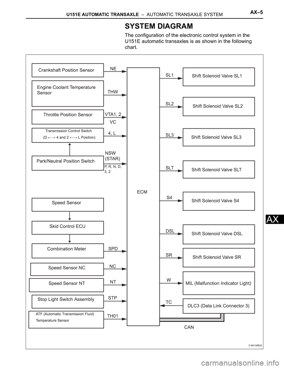
SYSTEM DIAGRAM
The configuration of the electronic control system in the
U151E automatic transaxles is as shown in the following
chart.
C160130E02
Page 1380 of 3000
AX–6U151E AUTOMATIC TRANSAXLE – AUTOMATIC TRANSAXLE SYSTEM
AX
SYSTEM DESCRIPTION
1. SYSTEM DESCRIPTION
(a) The ECT (Electronic controlled automatic
transmission/transaxle) is an automatic
transmission/transaxle that electronically controls
shift timing using the ECM. The ECM detects
electrical signals that indicate engine and driving
conditions, and controls the shift point, based on
driver habits and road conditions. As a result, fuel
efficiency and power transmission performance are
improved.
Shift shock has been reduced by controlling the
engine and transmission simultaneously.
In addition, the ECT has features such as follows:
• Diagnostic function.
• Fail-safe function when a malfunction occurs.