TOYOTA SIENNA 2007 Service Repair Manual
Manufacturer: TOYOTA, Model Year: 2007, Model line: SIENNA, Model: TOYOTA SIENNA 2007Pages: 3000, PDF Size: 52.26 MB
Page 2641 of 3000
BRAKE – REAR DRUM BRAKEBR–41
BR
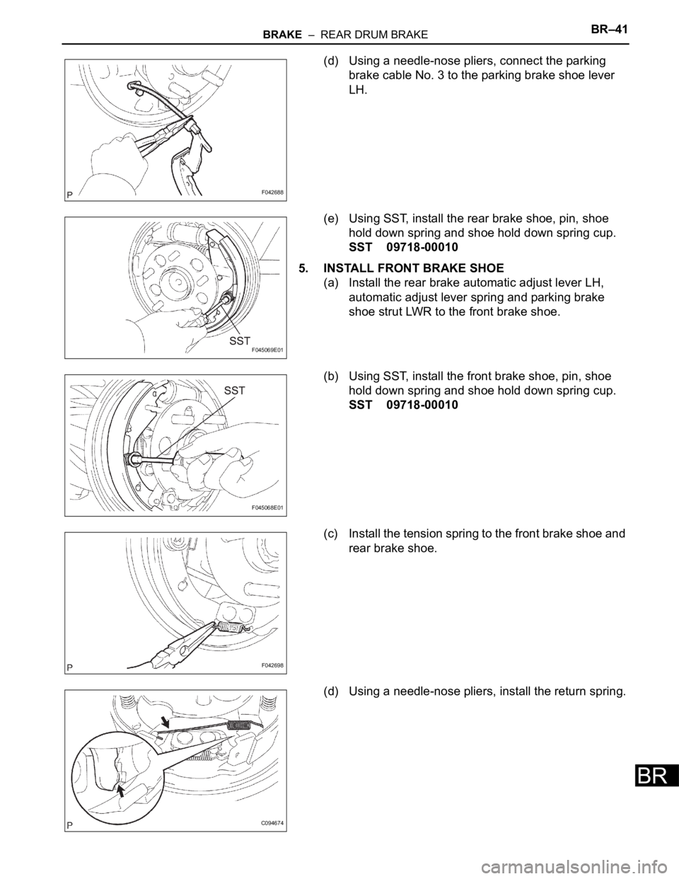
(d) Using a needle-nose pliers, connect the parking
brake cable No. 3 to the parking brake shoe lever
LH.
(e) Using SST, install the rear brake shoe, pin, shoe
hold down spring and shoe hold down spring cup.
SST 09718-00010
5. INSTALL FRONT BRAKE SHOE
(a) Install the rear brake automatic adjust lever LH,
automatic adjust lever spring and parking brake
shoe strut LWR to the front brake shoe.
(b) Using SST, install the front brake shoe, pin, shoe
hold down spring and shoe hold down spring cup.
SST 09718-00010
(c) Install the tension spring to the front brake shoe and
rear brake shoe.
(d) Using a needle-nose pliers, install the return spring.
F042688
F045069E01
F045068E01
F042698
C094674
Page 2642 of 3000
BR–42BRAKE – REAR DRUM BRAKE
BR
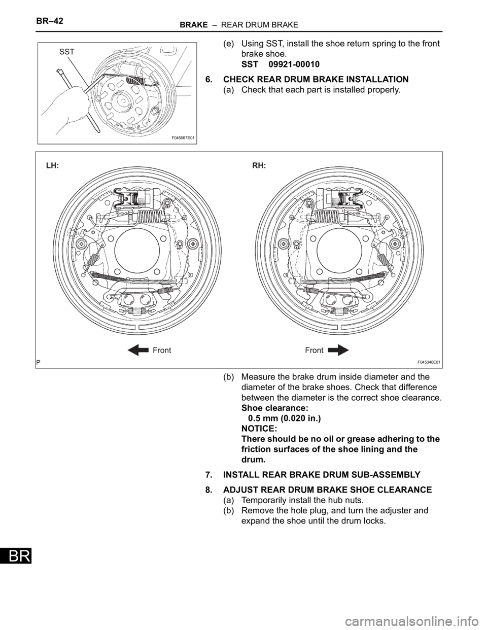
(e) Using SST, install the shoe return spring to the front
brake shoe.
SST 09921-00010
6. CHECK REAR DRUM BRAKE INSTALLATION
(a) Check that each part is installed properly.
(b) Measure the brake drum inside diameter and the
diameter of the brake shoes. Check that difference
between the diameter is the correct shoe clearance.
Shoe clearance:
0.5 mm (0.020 in.)
NOTICE:
There should be no oil or grease adhering to the
friction surfaces of the shoe lining and the
drum.
7. INSTALL REAR BRAKE DRUM SUB-ASSEMBLY
8. ADJUST REAR DRUM BRAKE SHOE CLEARANCE
(a) Temporarily install the hub nuts.
(b) Remove the hole plug, and turn the adjuster and
expand the shoe until the drum locks.
F045067E01
F045346E01
Page 2643 of 3000
BRAKE – REAR DRUM BRAKEBR–43
BR
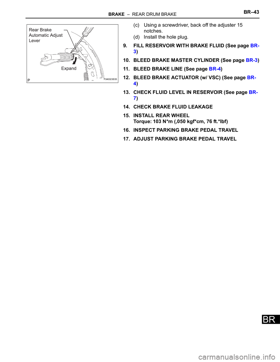
(c) Using a screwdriver, back off the adjuster 15
notches.
(d) Install the hole plug.
9. FILL RESERVOIR WITH BRAKE FLUID (See page BR-
3)
10. BLEED BRAKE MASTER CYLINDER (See page BR-3)
11. BLEED BRAKE LINE (See page BR-4)
12. BLEED BRAKE ACTUATOR (w/ VSC) (See page BR-
4)
13. CHECK FLUID LEVEL IN RESERVOIR (See page BR-
7)
14. CHECK BRAKE FLUID LEAKAGE
15. INSTALL REAR WHEEL
Torque: 103 N*m (,050 kgf*cm, 76 ft.*lbf)
16. INSPECT PARKING BRAKE PEDAL TRAVEL
17. ADJUST PARKING BRAKE PEDAL TRAVEL
F040023E05
Page 2644 of 3000
BRAKE – REAR DRUM BRAKEBR–39
BR
INSPECTION
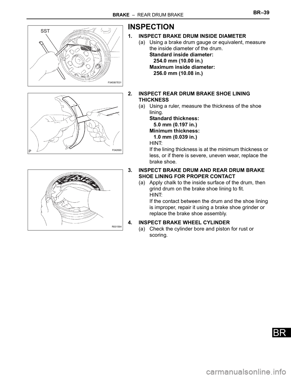
1. INSPECT BRAKE DRUM INSIDE DIAMETER
(a) Using a brake drum gauge or equivalent, measure
the inside diameter of the drum.
Standard inside diameter:
254.0 mm (10.00 in.)
Maximum inside diameter:
256.0 mm (10.08 in.)
2. INSPECT REAR DRUM BRAKE SHOE LINING
THICKNESS
(a) Using a ruler, measure the thickness of the shoe
lining.
Standard thickness:
5.0 mm (0.197 in.)
Minimum thickness:
1.0 mm (0.039 in.)
HINT:
If the lining thickness is at the minimum thickness or
less, or if there is severe, uneven wear, replace the
brake shoe.
3. INSPECT BRAKE DRUM AND REAR DRUM BRAKE
SHOE LINING FOR PROPER CONTACT
(a) Apply chalk to the inside surface of the drum, then
grind drum on the brake shoe lining to fit.
HINT:
If the contact between the drum and the shoe lining
is improper, repair it using a brake shoe grinder or
replace the brake shoe assembly.
4. INSPECT BRAKE WHEEL CYLINDER
(a) Check the cylinder bore and piston for rust or
scoring.
F045067E01
F042690
R001564
Page 2645 of 3000
BR–40BRAKE – REAR DRUM BRAKE
BR
REASSEMBLY
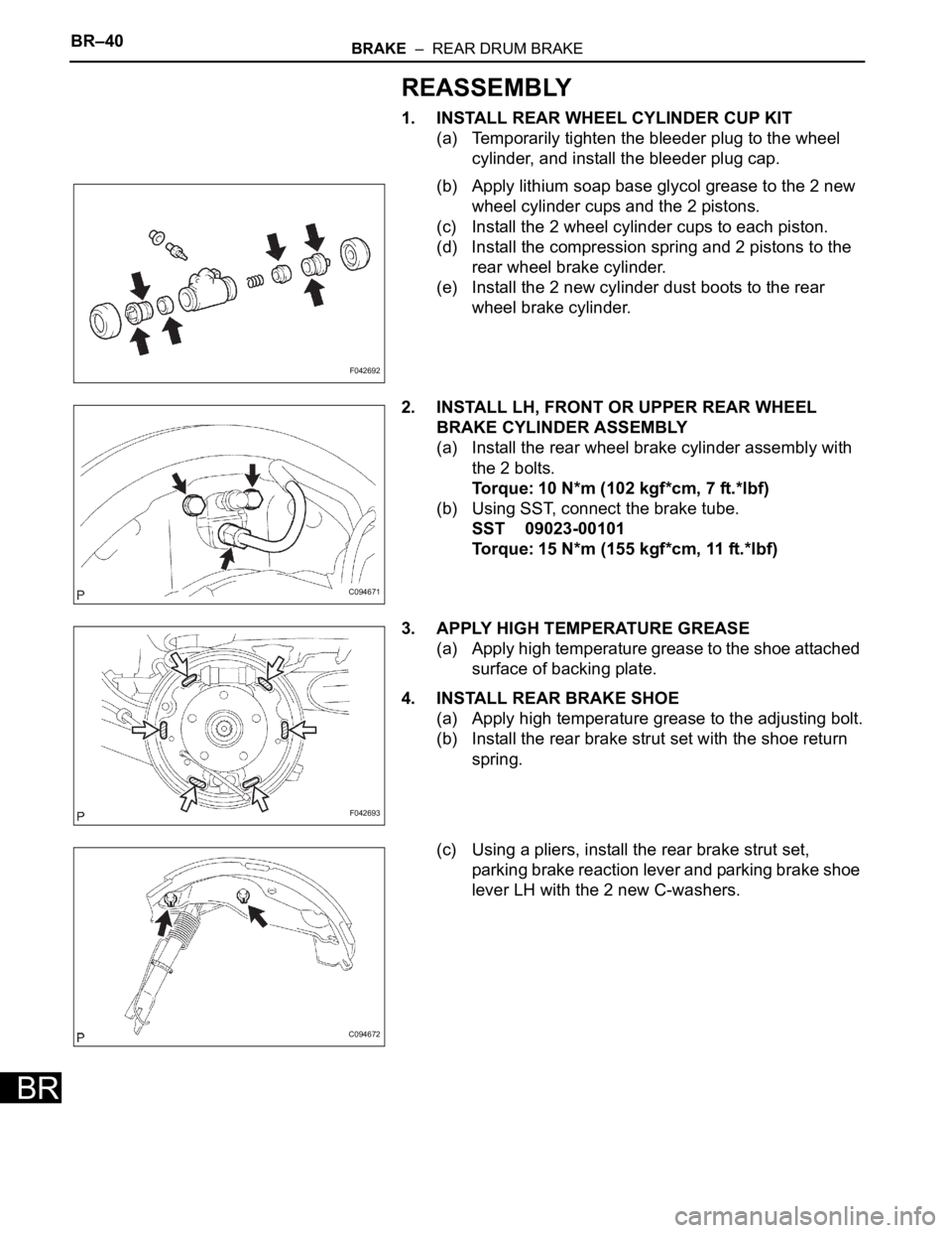
1. INSTALL REAR WHEEL CYLINDER CUP KIT
(a) Temporarily tighten the bleeder plug to the wheel
cylinder, and install the bleeder plug cap.
(b) Apply lithium soap base glycol grease to the 2 new
wheel cylinder cups and the 2 pistons.
(c) Install the 2 wheel cylinder cups to each piston.
(d) Install the compression spring and 2 pistons to the
rear wheel brake cylinder.
(e) Install the 2 new cylinder dust boots to the rear
wheel brake cylinder.
2. INSTALL LH, FRONT OR UPPER REAR WHEEL
BRAKE CYLINDER ASSEMBLY
(a) Install the rear wheel brake cylinder assembly with
the 2 bolts.
Torque: 10 N*m (102 kgf*cm, 7 ft.*lbf)
(b) Using SST, connect the brake tube.
SST 09023-00101
Torque: 15 N*m (155 kgf*cm, 11 ft.*lbf)
3. APPLY HIGH TEMPERATURE GREASE
(a) Apply high temperature grease to the shoe attached
surface of backing plate.
4. INSTALL REAR BRAKE SHOE
(a) Apply high temperature grease to the adjusting bolt.
(b) Install the rear brake strut set with the shoe return
spring.
(c) Using a pliers, install the rear brake strut set,
parking brake reaction lever and parking brake shoe
lever LH with the 2 new C-washers.
F042692
C094671
F042693
C094672
Page 2646 of 3000
BRAKE – REAR DRUM BRAKEBR–41
BR
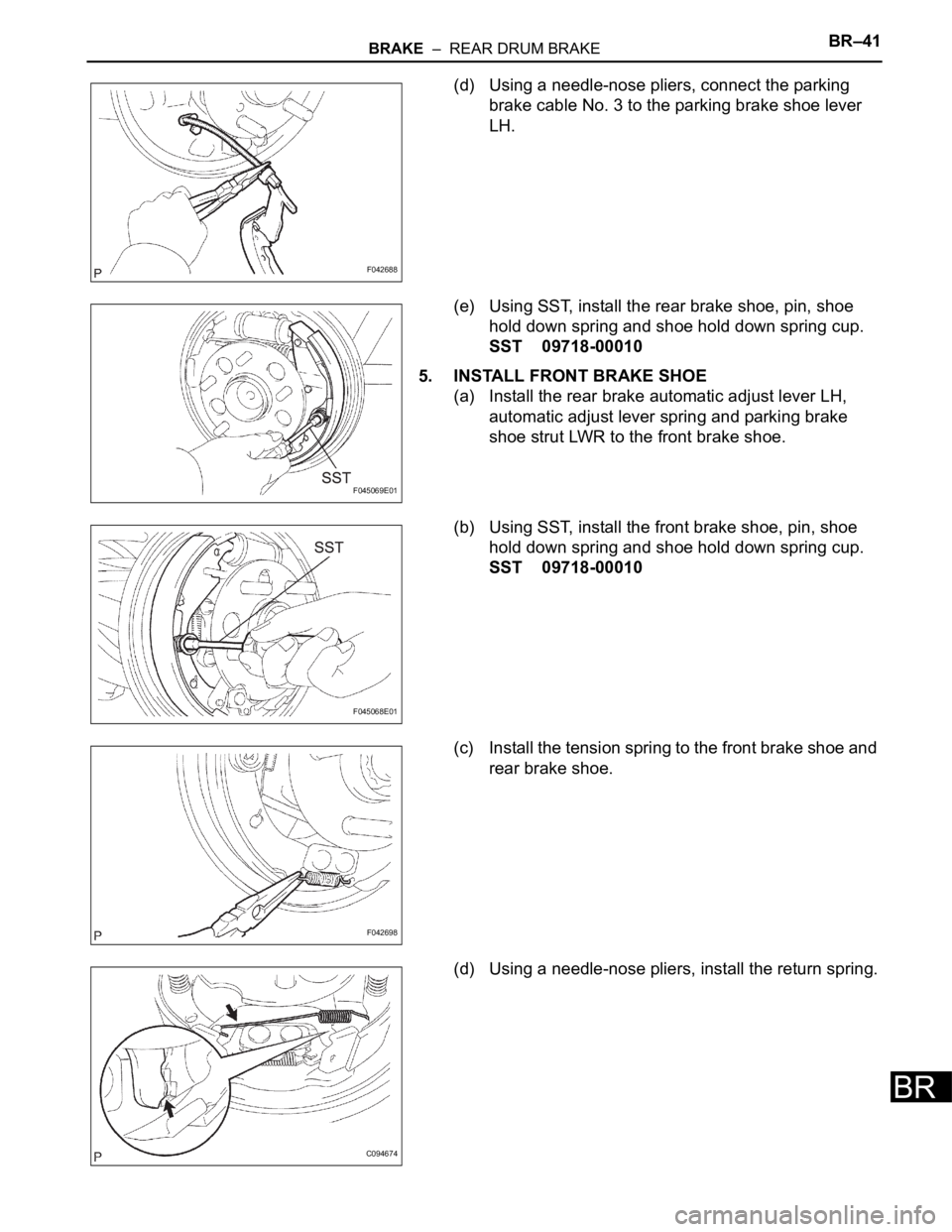
(d) Using a needle-nose pliers, connect the parking
brake cable No. 3 to the parking brake shoe lever
LH.
(e) Using SST, install the rear brake shoe, pin, shoe
hold down spring and shoe hold down spring cup.
SST 09718-00010
5. INSTALL FRONT BRAKE SHOE
(a) Install the rear brake automatic adjust lever LH,
automatic adjust lever spring and parking brake
shoe strut LWR to the front brake shoe.
(b) Using SST, install the front brake shoe, pin, shoe
hold down spring and shoe hold down spring cup.
SST 09718-00010
(c) Install the tension spring to the front brake shoe and
rear brake shoe.
(d) Using a needle-nose pliers, install the return spring.
F042688
F045069E01
F045068E01
F042698
C094674
Page 2647 of 3000
BR–42BRAKE – REAR DRUM BRAKE
BR
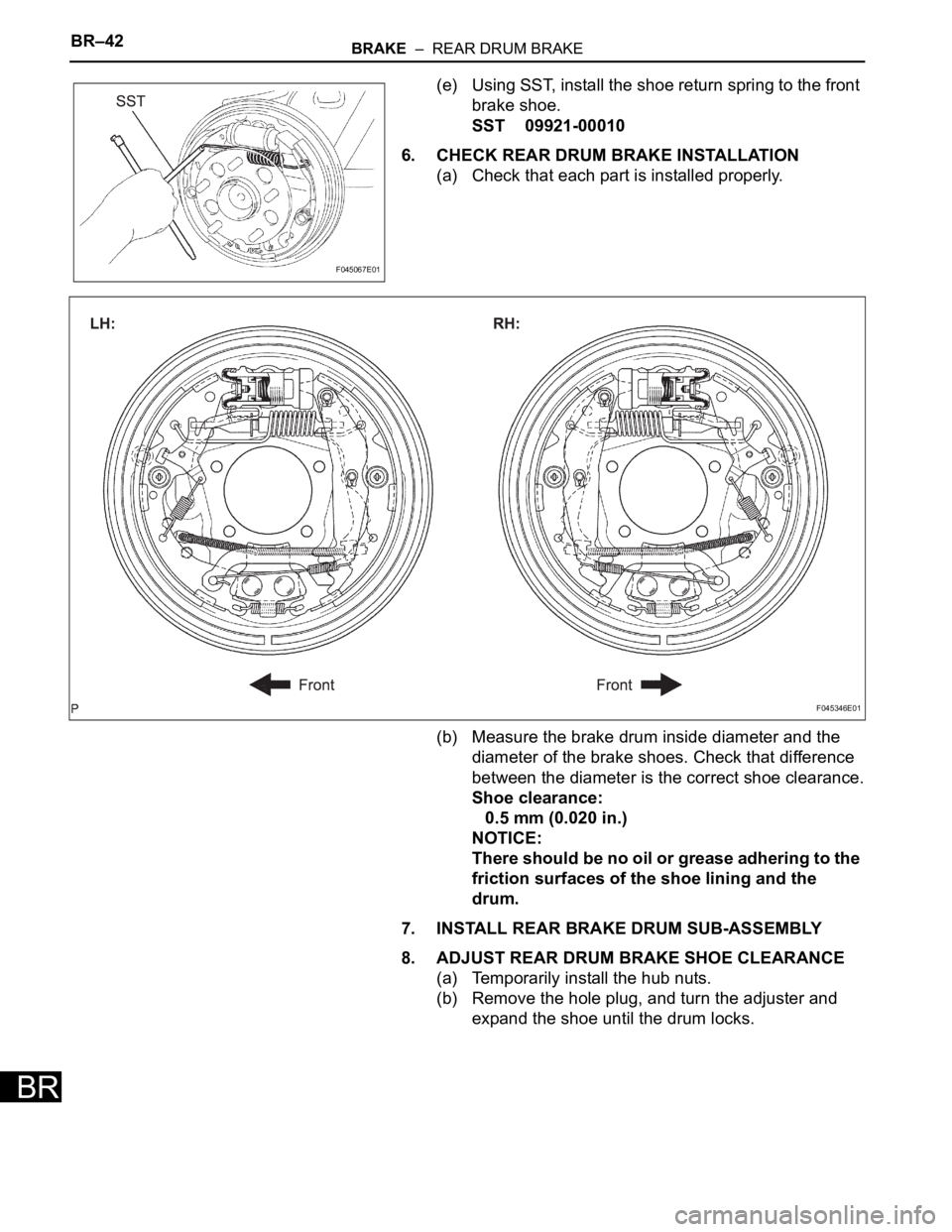
(e) Using SST, install the shoe return spring to the front
brake shoe.
SST 09921-00010
6. CHECK REAR DRUM BRAKE INSTALLATION
(a) Check that each part is installed properly.
(b) Measure the brake drum inside diameter and the
diameter of the brake shoes. Check that difference
between the diameter is the correct shoe clearance.
Shoe clearance:
0.5 mm (0.020 in.)
NOTICE:
There should be no oil or grease adhering to the
friction surfaces of the shoe lining and the
drum.
7. INSTALL REAR BRAKE DRUM SUB-ASSEMBLY
8. ADJUST REAR DRUM BRAKE SHOE CLEARANCE
(a) Temporarily install the hub nuts.
(b) Remove the hole plug, and turn the adjuster and
expand the shoe until the drum locks.
F045067E01
F045346E01
Page 2648 of 3000
BRAKE – REAR DRUM BRAKEBR–43
BR
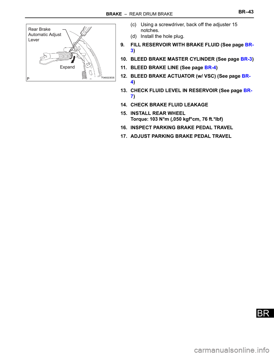
(c) Using a screwdriver, back off the adjuster 15
notches.
(d) Install the hole plug.
9. FILL RESERVOIR WITH BRAKE FLUID (See page BR-
3)
10. BLEED BRAKE MASTER CYLINDER (See page BR-3)
11. BLEED BRAKE LINE (See page BR-4)
12. BLEED BRAKE ACTUATOR (w/ VSC) (See page BR-
4)
13. CHECK FLUID LEVEL IN RESERVOIR (See page BR-
7)
14. CHECK BRAKE FLUID LEAKAGE
15. INSTALL REAR WHEEL
Torque: 103 N*m (,050 kgf*cm, 76 ft.*lbf)
16. INSPECT PARKING BRAKE PEDAL TRAVEL
17. ADJUST PARKING BRAKE PEDAL TRAVEL
F040023E05
Page 2649 of 3000
PARKING BRAKE – PARKING BRAKE PEDALPB–7
PB
REASSEMBLY
1. INSTALL PARKING BRAKE SWITCH ASSEMBLY
(a) Install the parking brake switch to the parking brake
pedal with the screw.
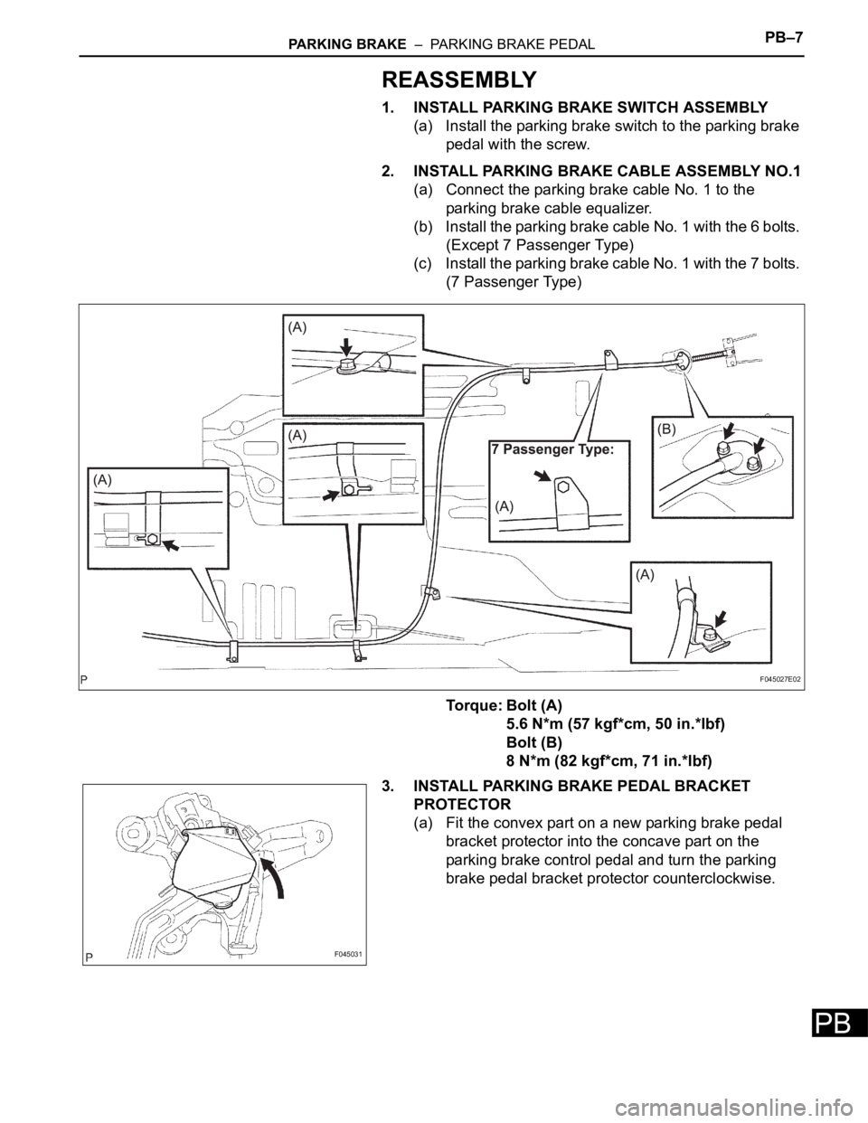
2. INSTALL PARKING BRAKE CABLE ASSEMBLY NO.1
(a) Connect the parking brake cable No. 1 to the
parking brake cable equalizer.
(b) Install the parking brake cable No. 1 with the 6 bolts.
(Except 7 Passenger Type)
(c) Install the parking brake cable No. 1 with the 7 bolts.
(7 Passenger Type)
Torque: Bolt (A)
5.6 N*m (57 kgf*cm, 50 in.*lbf)
Bolt (B)
8 N*m (82 kgf*cm, 71 in.*lbf)
3. INSTALL PARKING BRAKE PEDAL BRACKET
PROTECTOR
(a) Fit the convex part on a new parking brake pedal
bracket protector into the concave part on the
parking brake control pedal and turn the parking
brake pedal bracket protector counterclockwise.
F045027E02
F045031
Page 2650 of 3000
PB–8PARKING BRAKE – PARKING BRAKE PEDAL
PB
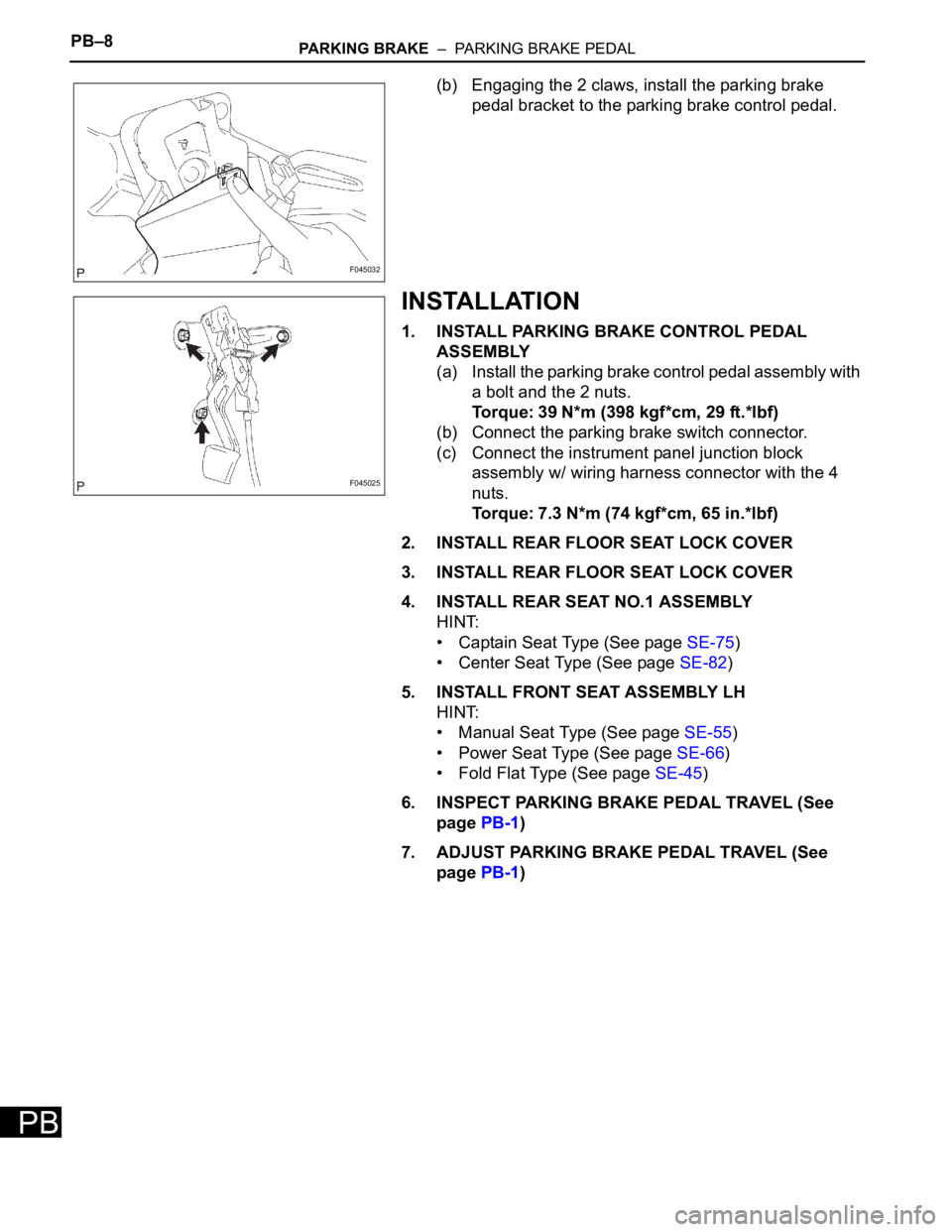
(b) Engaging the 2 claws, install the parking brake
pedal bracket to the parking brake control pedal.
INSTALLATION
1. INSTALL PARKING BRAKE CONTROL PEDAL
ASSEMBLY
(a) Install the parking brake control pedal assembly with
a bolt and the 2 nuts.
Torque: 39 N*m (398 kgf*cm, 29 ft.*lbf)
(b) Connect the parking brake switch connector.
(c) Connect the instrument panel junction block
assembly w/ wiring harness connector with the 4
nuts.
Torque: 7.3 N*m (74 kgf*cm, 65 in.*lbf)
2. INSTALL REAR FLOOR SEAT LOCK COVER
3. INSTALL REAR FLOOR SEAT LOCK COVER
4. INSTALL REAR SEAT NO.1 ASSEMBLY
HINT:
• Captain Seat Type (See page SE-75)
• Center Seat Type (See page SE-82)
5. INSTALL FRONT SEAT ASSEMBLY LH
HINT:
• Manual Seat Type (See page SE-55)
• Power Seat Type (See page SE-66)
• Fold Flat Type (See page SE-45)
6. INSPECT PARKING BRAKE PEDAL TRAVEL (See
page PB-1)
7. ADJUST PARKING BRAKE PEDAL TRAVEL (See
page PB-1)
F045032
F045025