TOYOTA SIENNA 2007 Service Repair Manual
Manufacturer: TOYOTA, Model Year: 2007, Model line: SIENNA, Model: TOYOTA SIENNA 2007Pages: 3000, PDF Size: 52.26 MB
Page 2611 of 3000
BRAKE – BRAKE MASTER CYLINDERBR–15
BR
REMOVAL
NOTICE:
• Do not adjust the brake booster push rod.
• Do not change the combination of the diameter
converting unit and brake.
1. DRAIN BRAKE FLUID
NOTICE:
Wash the brake fluid off immediately if it attaches to
any painted surfaces.
2. SEPARATE BATTERY NEGATIVE TERMINAL
3. REMOVE AIR CLEANER ASSEMBLY WITH HOSE
4. REMOVE COWL TOP PANEL SUB-ASSEMBLY
OUTER FRONT (See page SP-13)
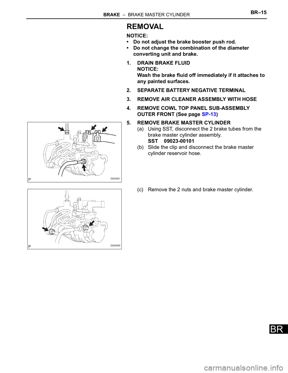
5. REMOVE BRAKE MASTER CYLINDER
(a) Using SST, disconnect the 2 brake tubes from the
brake master cylinder assembly.
SST 09023-00101
(b) Slide the clip and disconnect the brake master
cylinder reservoir hose.
(c) Remove the 2 nuts and brake master cylinder.
G024301
G024300
Page 2612 of 3000
BR–28BRAKE – FRONT BRAKE
BR
INSPECTION
1. INSPECT BRAKE CYLINDER AND PISTON
(a) Check the brake cylinder bore and front disc brake
piston for rust or scoring.
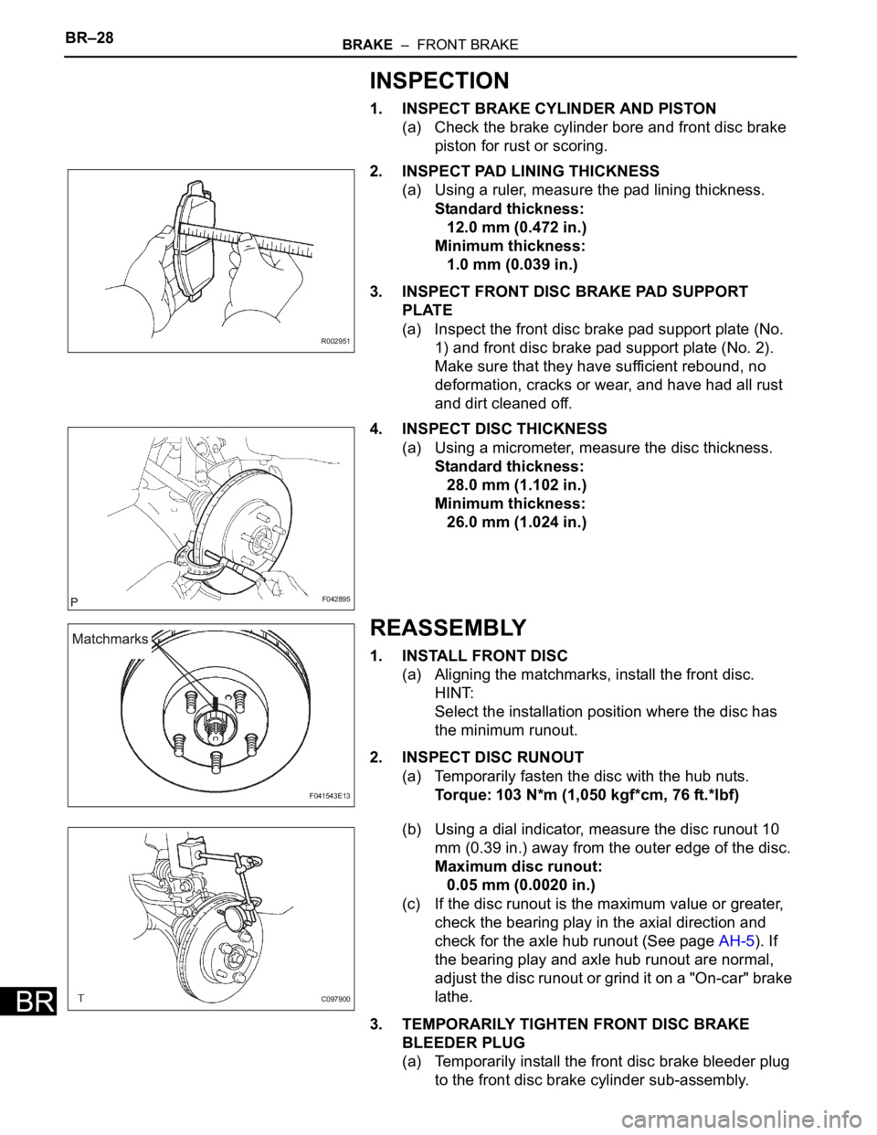
2. INSPECT PAD LINING THICKNESS
(a) Using a ruler, measure the pad lining thickness.
Standard thickness:
12.0 mm (0.472 in.)
Minimum thickness:
1.0 mm (0.039 in.)
3. INSPECT FRONT DISC BRAKE PAD SUPPORT
PLATE
(a) Inspect the front disc brake pad support plate (No.
1) and front disc brake pad support plate (No. 2).
Make sure that they have sufficient rebound, no
deformation, cracks or wear, and have had all rust
and dirt cleaned off.
4. INSPECT DISC THICKNESS
(a) Using a micrometer, measure the disc thickness.
Standard thickness:
28.0 mm (1.102 in.)
Minimum thickness:
26.0 mm (1.024 in.)
REASSEMBLY
1. INSTALL FRONT DISC
(a) Aligning the matchmarks, install the front disc.
HINT:
Select the installation position where the disc has
the minimum runout.
2. INSPECT DISC RUNOUT
(a) Temporarily fasten the disc with the hub nuts.
Torque: 103 N*m (1,050 kgf*cm, 76 ft.*lbf)
(b) Using a dial indicator, measure the disc runout 10
mm (0.39 in.) away from the outer edge of the disc.
Maximum disc runout:
0.05 mm (0.0020 in.)
(c) If the disc runout is the maximum value or greater,
check the bearing play in the axial direction and
check for the axle hub runout (See page AH-5). If
the bearing play and axle hub runout are normal,
adjust the disc runout or grind it on a "On-car" brake
lathe.
3. TEMPORARILY TIGHTEN FRONT DISC BRAKE
BLEEDER PLUG
(a) Temporarily install the front disc brake bleeder plug
to the front disc brake cylinder sub-assembly.
R002951
F042895
F041543E13
C097900
Page 2613 of 3000
BRAKE – FRONT BRAKEBR–29
BR
4. INSTALL FRONT DISC BRAKE BLEEDER PLUG CAP
5. INSTALL PISTON SEAL
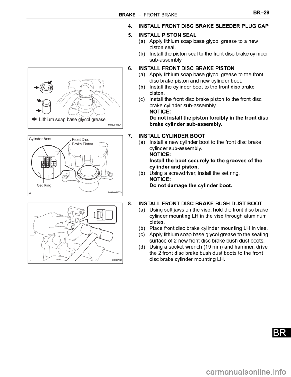
(a) Apply lithium soap base glycol grease to a new
piston seal.
(b) Install the piston seal to the front disc brake cylinder
sub-assembly.
6. INSTALL FRONT DISC BRAKE PISTON
(a) Apply lithium soap base glycol grease to the front
disc brake piston and new cylinder boot.
(b) Install the cylinder boot to the front disc brake
piston.
(c) Install the front disc brake piston to the front disc
brake cylinder sub-assembly.
NOTICE:
Do not install the piston forcibly in the front disc
brake cylinder sub-assembly.
7. INSTALL CYLINDER BOOT
(a) Install a new cylinder boot to the front disc brake
cylinder sub-assembly.
NOTICE:
Install the boot securely to the grooves of the
cylinder and piston.
(b) Using a screwdriver, install the set ring.
NOTICE:
Do not damage the cylinder boot.
8. INSTALL FRONT DISC BRAKE BUSH DUST BOOT
(a) Using soft jaws on the vise, hold the front disc brake
cylinder mounting LH in the vise through aluminum
plates.
(b) Place front disc brake cylinder mounting LH in vise.
(c) Apply lithium soap base glycol grease to the sealing
surface of 2 new front disc brake bush dust boots.
(d) Using a socket wrench (19 mm) and hammer, drive
the 2 front disc brake bush dust boots to the front
disc brake cylinder mounting LH.
F045277E04
F042832E03
C068792
Page 2614 of 3000
BR–18BRAKE – BRAKE BOOSTER
BR
BRAKE
BRAKE
BRAKE BOOSTER
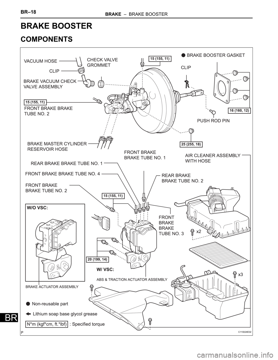
COMPONENTS
C119324E02
Page 2615 of 3000
BRAKE – BRAKE BOOSTERBR–19
BR
ON-VEHICLE INSPECTION
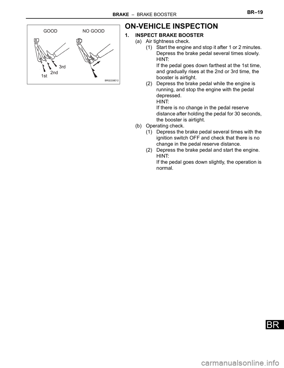
1. INSPECT BRAKE BOOSTER
(a) Air tightness check.
(1) Start the engine and stop it after 1 or 2 minutes.
Depress the brake pedal several times slowly.
HINT:
If the pedal goes down farthest at the 1st time,
and gradually rises at the 2nd or 3rd time, the
booster is airtight.
(2) Depress the brake pedal while the engine is
running, and stop the engine with the pedal
depressed.
HINT:
If there is no change in the pedal reserve
distance after holding the pedal for 30 seconds,
the booster is airtight.
(b) Operating check.
(1) Depress the brake pedal several times with the
ignition switch OFF and check that there is no
change in the pedal reserve distance.
(2) Depress the brake pedal and start the engine.
HINT:
If the pedal goes down slightly, the operation is
normal.
BR02238E12
Page 2616 of 3000
BR–30BRAKE – FRONT BRAKE
BR
INSTALLATION
HINT:
Install the RH side by the same procedure as the LH side.
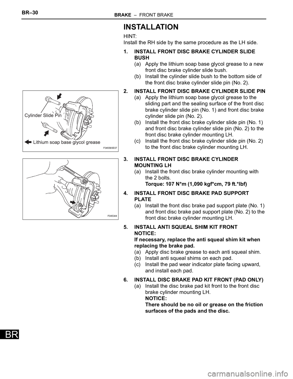
1. INSTALL FRONT DISC BRAKE CYLINDER SLIDE
BUSH
(a) Apply the lithium soap base glycol grease to a new
front disc brake cylinder slide bush.
(b) Install the cylinder slide bush to the bottom side of
the front disc brake cylinder slide pin (No. 2).
2. INSTALL FRONT DISC BRAKE CYLINDER SLIDE PIN
(a) Apply the lithium soap base glycol grease to the
sliding part and the sealing surface of the front disc
brake cylinder slide pin (No. 1) and front disc brake
cylinder slide pin (No. 2).
(b) Install the front disc brake cylinder slide pin (No. 1)
and front disc brake cylinder slide pin (No. 2) to the
front disc brake cylinder mounting LH.
(c) Install the front disc brake cylinder slide pin (No. 2)
to the front disc brake cylinder mounting LH.
3. INSTALL FRONT DISC BRAKE CYLINDER
MOUNTING LH
(a) Install the front disc brake cylinder mounting with
the 2 bolts.
Torque: 107 N*m (1,090 kgf*cm, 79 ft.*lbf)
4. INSTALL FRONT DISC BRAKE PAD SUPPORT
PLATE
(a) Install the front disc brake pad support plate (No. 1)
and front disc brake pad support plate (No. 2) to the
front disc brake cylinder mounting LH.
5. INSTALL ANTI SQUEAL SHIM KIT FRONT
NOTICE:
If necessary, replace the anti squeal shim kit when
replacing the brake pad.
(a) Apply disc brake grease to each anti squeal shim.
(b) Install anti squeal shims on each pad.
(c) Install the pad wear indicator plate facing upward,
and install each pad.
6. INSTALL DISC BRAKE PAD KIT FRONT (PAD ONLY)
(a) Install the disc brake pad kit front to the front disc
brake cylinder mounting LH.
NOTICE:
There should be no oil or grease on the friction
surfaces of the pads and the disc.
F045565E07
F045344
Page 2617 of 3000
BRAKE – FRONT BRAKEBR–31
BR
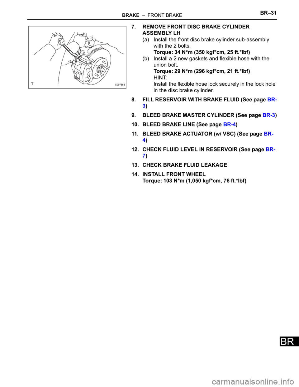
7. REMOVE FRONT DISC BRAKE CYLINDER
ASSEMBLY LH
(a) Install the front disc brake cylinder sub-assembly
with the 2 bolts.
Torque: 34 N*m (350 kgf*cm, 25 ft.*lbf)
(b) Install a 2 new gaskets and flexible hose with the
union bolt.
Torque: 29 N*m (296 kgf*cm, 21 ft.*lbf)
HINT:
Install the flexible hose lock securely in the lock hole
in the disc brake cylinder.
8. FILL RESERVOIR WITH BRAKE FLUID (See page BR-
3)
9. BLEED BRAKE MASTER CYLINDER (See page BR-3)
10. BLEED BRAKE LINE (See page BR-4)
11. BLEED BRAKE ACTUATOR (w/ VSC) (See page BR-
4)
12. CHECK FLUID LEVEL IN RESERVOIR (See page BR-
7)
13. CHECK BRAKE FLUID LEAKAGE
14. INSTALL FRONT WHEEL
Torque: 103 N*m (1,050 kgf*cm, 76 ft.*lbf)
C097868
Page 2618 of 3000
BRAKE – FRONT BRAKEBR–23
BR
BRAKE
BRAKE
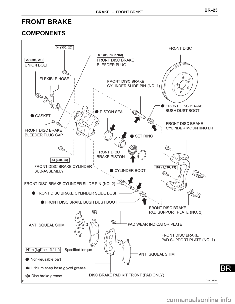
FRONT BRAKE
COMPONENTS
C119326E02
Page 2619 of 3000
BR–24BRAKE – FRONT BRAKE
BR
REMOVAL
HINT:
Remove the RH side by the same procedure as the LH side.
1. REMOVE FRONT WHEEL
2. DRAIN BRAKE FLUID
NOTICE:
Wash the brake fluid off immediately if it attaches to
any painted surface.
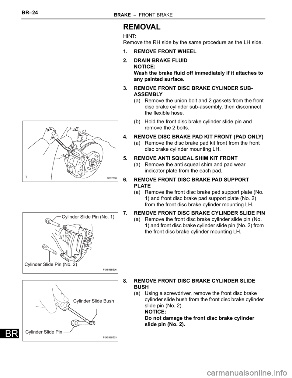
3. REMOVE FRONT DISC BRAKE CYLINDER SUB-
ASSEMBLY
(a) Remove the union bolt and 2 gaskets from the front
disc brake cylinder sub-assembly, then disconnect
the flexible hose.
(b) Hold the front disc brake cylinder slide pin and
remove the 2 bolts.
4. REMOVE DISC BRAKE PAD KIT FRONT (PAD ONLY)
(a) Remove the disc brake pad kit front from the front
disc brake cylinder mounting LH.
5. REMOVE ANTI SQUEAL SHIM KIT FRONT
(a) Remove the anti squeal shim and pad wear
indicator plate from the each pad.
6. REMOVE FRONT DISC BRAKE PAD SUPPORT
PLATE
(a) Remove the front disc brake pad support plate (No.
1) and front disc brake pad support plate (No. 2)
from the front disc brake cylinder mounting LH.
7. REMOVE FRONT DISC BRAKE CYLINDER SLIDE PIN
(a) Remove the front disc brake cylinder slide pin (No.
1) and front disc brake cylinder slide pin (No. 2) from
the front disc brake cylinder mounting LH.
8. REMOVE FRONT DISC BRAKE CYLINDER SLIDE
BUSH
(a) Using a screwdriver, remove the front disc brake
cylinder slide bush from the front disc brake cylinder
slide pin (No. 2).
NOTICE:
Do not damage the front disc brake cylinder
slide pin (No. 2).
C097868
F045565E06
F045566E03
Page 2620 of 3000
BRAKE – FRONT BRAKEBR–25
BR
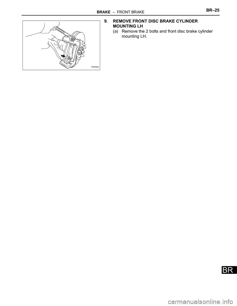
9. REMOVE FRONT DISC BRAKE CYLINDER
MOUNTING LH
(a) Remove the 2 bolts and front disc brake cylinder
mounting LH.
F045344