engine oil TOYOTA SIENNA 2007 Service Repair Manual
[x] Cancel search | Manufacturer: TOYOTA, Model Year: 2007, Model line: SIENNA, Model: TOYOTA SIENNA 2007Pages: 3000, PDF Size: 52.26 MB
Page 1885 of 3000
U151F AUTOMATIC TRANSAXLE – AUTOMATIC TRANSAXLE ASSEMBLYAX–169
AX
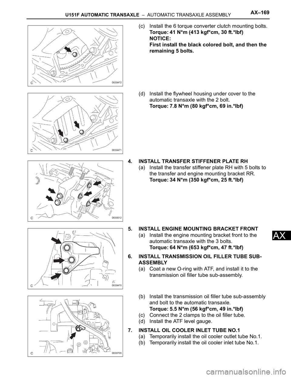
(c) Install the 6 torque converter clutch mounting bolts.
Torque: 41 N*m (413 kgf*cm, 30 ft.*lbf)
NOTICE:
First install the black colored bolt, and then the
remaining 5 bolts.
(d) Install the flywheel housing under cover to the
automatic transaxle with the 2 bolt.
Torque: 7.8 N*m (80 kgf*cm, 69 in.*lbf)
4. INSTALL TRANSFER STIFFENER PLATE RH
(a) Install the transfer stiffener plate RH with 5 bolts to
the transfer and engine mounting bracket RR.
Torque: 34 N*m (350 kgf*cm, 25 ft.*lbf)
5. INSTALL ENGINE MOUNTING BRACKET FRONT
(a) Install the engine mounting bracket front to the
automatic transaxle with the 3 bolts.
Torque: 64 N*m (653 kgf*cm, 47 ft.*lbf)
6. INSTALL TRANSMISSION OIL FILLER TUBE SUB-
ASSEMBLY
(a) Coat a new O-ring with ATF, and install it to the
transmission oil filler tube sub-assembly.
(b) Install the transmission oil filler tube sub-assembly
and bolt to the automatic transaxle.
Torque: 5.5 N*m (56 kgf*cm, 49 in.*lbf)
(c) Connect the 2 clamps to the oil filler tube.
(d) Install the ATF level gauge.
7. INSTALL OIL COOLER INLET TUBE NO.1
(a) Temporarily install the oil cooler outlet tube No.1.
(b) Temporarily install the oil cooler inlet tube No.1.
D030472
D030471
D030512
D030470
D030700
Page 2031 of 3000
TF–8TRANSFER – TRANSFER ASSEMBLY
TF
REMOVAL
1. REMOVE ENGINE AND TRANSAXLE
HINT:
(See page EM-26)
2. REMOVE AUTOMATIC TRANSMISSION WITH
TRANSFER
HINT:
(See page AX-164)
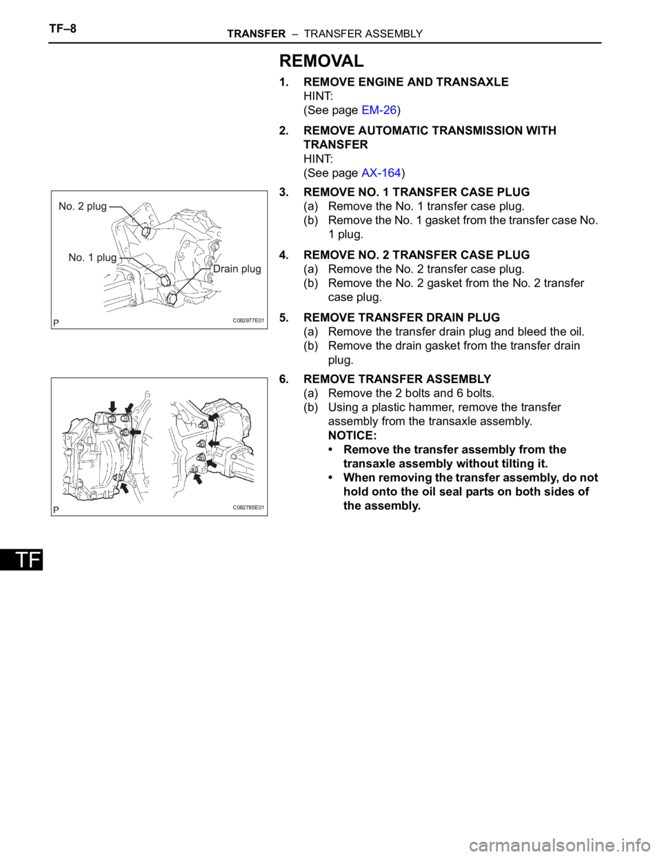
3. REMOVE NO. 1 TRANSFER CASE PLUG
(a) Remove the No. 1 transfer case plug.
(b) Remove the No. 1 gasket from the transfer case No.
1 plug.
4. REMOVE NO. 2 TRANSFER CASE PLUG
(a) Remove the No. 2 transfer case plug.
(b) Remove the No. 2 gasket from the No. 2 transfer
case plug.
5. REMOVE TRANSFER DRAIN PLUG
(a) Remove the transfer drain plug and bleed the oil.
(b) Remove the drain gasket from the transfer drain
plug.
6. REMOVE TRANSFER ASSEMBLY
(a) Remove the 2 bolts and 6 bolts.
(b) Using a plastic hammer, remove the transfer
assembly from the transaxle assembly.
NOTICE:
• Remove the transfer assembly from the
transaxle assembly without tilting it.
• When removing the transfer assembly, do not
hold onto the oil seal parts on both sides of
the assembly.
C082977E01
C082785E01
Page 2032 of 3000
TRANSFER – TRANSFER ASSEMBLYTF–9
TF
INSTALLATION
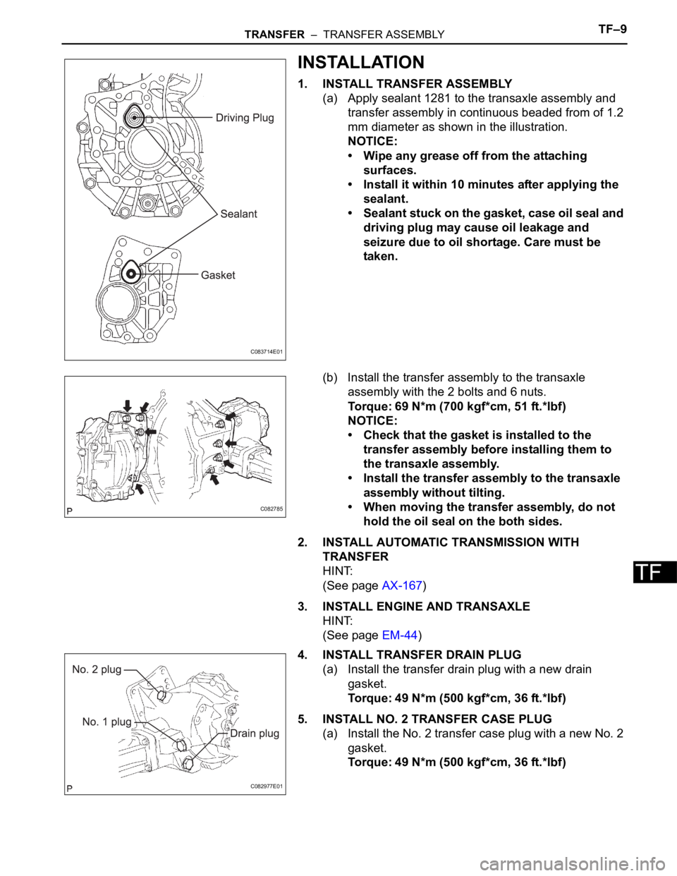
1. INSTALL TRANSFER ASSEMBLY
(a) Apply sealant 1281 to the transaxle assembly and
transfer assembly in continuous beaded from of 1.2
mm diameter as shown in the illustration.
NOTICE:
• Wipe any grease off from the attaching
surfaces.
• Install it within 10 minutes after applying the
sealant.
• Sealant stuck on the gasket, case oil seal and
driving plug may cause oil leakage and
seizure due to oil shortage. Care must be
taken.
(b) Install the transfer assembly to the transaxle
assembly with the 2 bolts and 6 nuts.
Torque: 69 N*m (700 kgf*cm, 51 ft.*lbf)
NOTICE:
• Check that the gasket is installed to the
transfer assembly before installing them to
the transaxle assembly.
• Install the transfer assembly to the transaxle
assembly without tilting.
• When moving the transfer assembly, do not
hold the oil seal on the both sides.
2. INSTALL AUTOMATIC TRANSMISSION WITH
TRANSFER
HINT:
(See page AX-167)
3. INSTALL ENGINE AND TRANSAXLE
HINT:
(See page EM-44)
4. INSTALL TRANSFER DRAIN PLUG
(a) Install the transfer drain plug with a new drain
gasket.
Torque: 49 N*m (500 kgf*cm, 36 ft.*lbf)
5. INSTALL NO. 2 TRANSFER CASE PLUG
(a) Install the No. 2 transfer case plug with a new No. 2
gasket.
Torque: 49 N*m (500 kgf*cm, 36 ft.*lbf)
C083714E01
C082785
C082977E01
Page 2168 of 3000
AXLE – FRONT AXLE HUBAH–9
AH
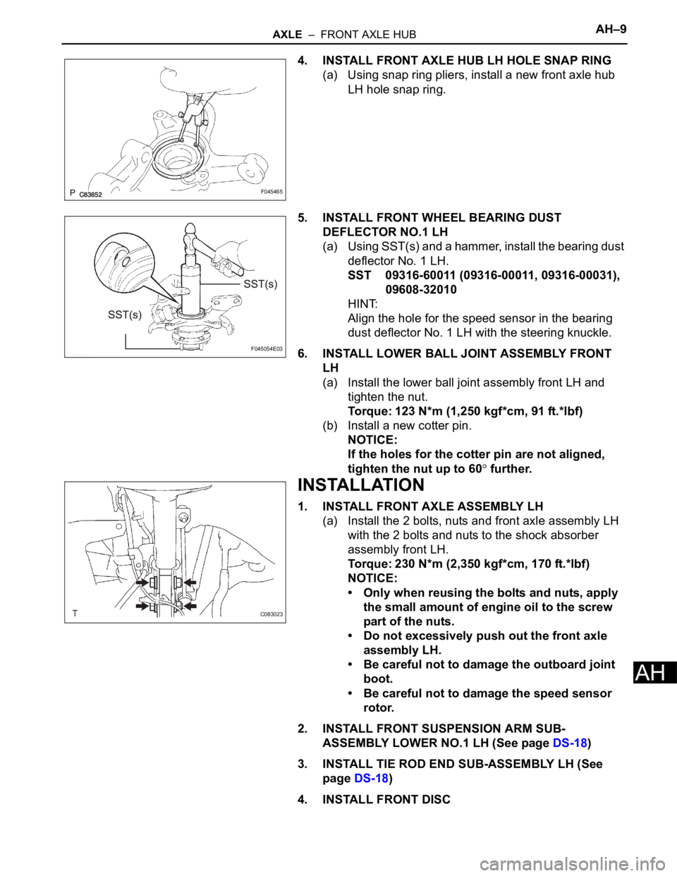
4. INSTALL FRONT AXLE HUB LH HOLE SNAP RING
(a) Using snap ring pliers, install a new front axle hub
LH hole snap ring.
5. INSTALL FRONT WHEEL BEARING DUST
DEFLECTOR NO.1 LH
(a) Using SST(s) and a hammer, install the bearing dust
deflector No. 1 LH.
SST 09316-60011 (09316-00011, 09316-00031),
09608-32010
HINT:
Align the hole for the speed sensor in the bearing
dust deflector No. 1 LH with the steering knuckle.
6. INSTALL LOWER BALL JOINT ASSEMBLY FRONT
LH
(a) Install the lower ball joint assembly front LH and
tighten the nut.
Torque: 123 N*m (1,250 kgf*cm, 91 ft.*lbf)
(b) Install a new cotter pin.
NOTICE:
If the holes for the cotter pin are not aligned,
tighten the nut up to 60
further.
INSTALLATION
1. INSTALL FRONT AXLE ASSEMBLY LH
(a) Install the 2 bolts, nuts and front axle assembly LH
with the 2 bolts and nuts to the shock absorber
assembly front LH.
Torque: 230 N*m (2,350 kgf*cm, 170 ft.*lbf)
NOTICE:
• Only when reusing the bolts and nuts, apply
the small amount of engine oil to the screw
part of the nuts.
• Do not excessively push out the front axle
assembly LH.
• Be careful not to damage the outboard joint
boot.
• Be careful not to damage the speed sensor
rotor.
2. INSTALL FRONT SUSPENSION ARM SUB-
ASSEMBLY LOWER NO.1 LH (See page DS-18)
3. INSTALL TIE ROD END SUB-ASSEMBLY LH (See
page DS-18)
4. INSTALL FRONT DISC
F045465
F045054E03
C083023
Page 2917 of 3000
AIR CONDITIONING – REFRIGERANTAC–173
AC
REPLACEMENT
1. DISCHARGE REFRIGERANT FROM
REFRIGERATION SYSTEM
SST 07110-58060 (07117-58080, 07117-58090,
07117-78050, 07117-88060, 07117-88070,
07117-88080)
(a) Turn the A/C switch to ON.
(b) Operating the cooler compressor at the engine rpm
of approx. 1,000 for 5 to 6 minutes, circulate the
refrigerant and collect the compressor oil remaining
in each component into the cooler compressor as
much as possible.
(c) Stop the engine.
(d) Let the refrigerant gas out.
SST 07110-58060 (07117-58080, 07117-78050,
07117-88060, 07117-88070, 07117-88080)
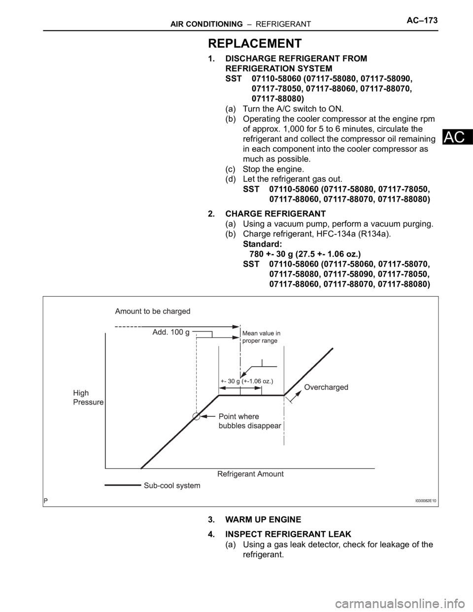
2. CHARGE REFRIGERANT
(a) Using a vacuum pump, perform a vacuum purging.
(b) Charge refrigerant, HFC-134a (R134a).
Standard:
780 +- 30 g (27.5 +- 1.06 oz.)
SST 07110-58060 (07117-58060, 07117-58070,
07117-58080, 07117-58090, 07117-78050,
07117-88060, 07117-88070, 07117-88080)
3. WARM UP ENGINE
4. INSPECT REFRIGERANT LEAK
(a) Using a gas leak detector, check for leakage of the
refrigerant.
I030082E10
Page 2959 of 3000

AIR CONDITIONING – COMPRESSOR AND MAGNETIC CLUTCHAC–233
AC
(d) Install the suction hose sub-assembly onto the
compressor and magnetic clutch with the bolt.
Torque: 5.4 N*m (55 kgf*cm, 48 in.*lbf)
3. INSTALL DISCHARGE HOSE SUB-ASSEMBLY
(a) Remove the attached vinyl tape from the hose.
(b) Apply sufficient compressor oil to a new O-ring and
the fitting surface of the compressor and magnetic
clutch.
Compressor oil:
ND-OIL 8 or equivalent
(c) Install the O-ring onto the discharge hose sub-
assembly.
(d) Install the discharge hose sub-assembly onto the
compressor and magnetic clutch with the bolt.
Torque: 5.4 N*m (55 kgf*cm, 48 in.*lbf)
4. INSTALL RADIATOR AND FAN ASSEMBLY
(See page CO-39)
5. INSTALL V-RIBBED BELT (See page EM-7)
6. INSTALL FRONT FENDER APRON SEAL RH (See
page EM-62)
7. INSTALL FRONT WHEEL RH
8. CHARGE WITH REFRIGERANT (See page AC-173)
9. WARM UP ENGINE
10. INSPECT FOR REFRIGERANT LEAK (See page AC-
173)
E145265
E145264
Page 2973 of 3000

AIR CONDITIONING – COMPRESSOR AND MAGNETIC CLUTCHAC–233
AC
(d) Install the suction hose sub-assembly onto the
compressor and magnetic clutch with the bolt.
Torque: 5.4 N*m (55 kgf*cm, 48 in.*lbf)
3. INSTALL DISCHARGE HOSE SUB-ASSEMBLY
(a) Remove the attached vinyl tape from the hose.
(b) Apply sufficient compressor oil to a new O-ring and
the fitting surface of the compressor and magnetic
clutch.
Compressor oil:
ND-OIL 8 or equivalent
(c) Install the O-ring onto the discharge hose sub-
assembly.
(d) Install the discharge hose sub-assembly onto the
compressor and magnetic clutch with the bolt.
Torque: 5.4 N*m (55 kgf*cm, 48 in.*lbf)
4. INSTALL RADIATOR AND FAN ASSEMBLY
(See page CO-39)
5. INSTALL V-RIBBED BELT (See page EM-7)
6. INSTALL FRONT FENDER APRON SEAL RH (See
page EM-62)
7. INSTALL FRONT WHEEL RH
8. CHARGE WITH REFRIGERANT (See page AC-173)
9. WARM UP ENGINE
10. INSPECT FOR REFRIGERANT LEAK (See page AC-
173)
E145265
E145264