Position TOYOTA SIENNA 2007 Service Owner's Guide
[x] Cancel search | Manufacturer: TOYOTA, Model Year: 2007, Model line: SIENNA, Model: TOYOTA SIENNA 2007Pages: 3000, PDF Size: 52.26 MB
Page 278 of 3000

PM–4PARK ASSIST / MONITORING – REAR VIEW MONITOR SYSTEM
PM
(b) Images are difficult to discern even in normal
conditions if:
(1) Camera screen is frosted over (the image
immediately after turning the ignition switch to
the on position may be blurred or darker than
normal).
(2) A strong beam of light, such as a sunbeam or
headlight, hits the camera.
(3) It is too dark around the camera (at night, etc.).
(4) The ambient temperature around the camera is
either too high or too low.
HINT:
When a strong light, such as a sunbeam
reflected off the vehicle's body, hits the camera,
the image may be blurred. This is called the
"SMEAR" phenomenon, peculiar to the CCD
camera.
Page 279 of 3000

OTHER SYSTEM – CIGARETTE LIGHTEROT–5
OT
REMOVAL
1. REMOVE INSTRUMENT CLUSTER CENTER NO. 1
FINISH PANEL (See page IP-8)
2. REMOVE INSTRUMENT CLUSTER CENTER NO. 2
FINISH PANEL
3. REMOVE SHIFT LEVER KNOB SUB-ASSEMBLY (See
page IP-8)
4. REMOVE POSITION INDICATOR HOUSING
ASSEMBLY (See page IP-9)
5. REMOVE INSTRUMENT CLUSTER CENTER LOWER
FINISH PANEL SUB-ASSEMBLY (See page IP-9)
6. REMOVE CIGARETTE LIGHTER COVER
(a) Release the 2 claw fittings and remove the cigarette
lighter cover.
7. REMOVE CIGARETTE LIGHTER ASSEMBLY
(a) Remove the cigarette lighter knob.
(b) Release the 2 claw fittings and remove the cigarette
lighter assembly.
INSTALLATION
1. INSTALL CIGARETTE LIGHTER ASSEMBLY
(a) Engage the 2 claws to install the cigarette lighter
assembly.
(b) Install the cigarette lighter knob.
I035589E01
I037256E01
I037256E01
Page 280 of 3000

OT–6OTHER SYSTEM – CIGARETTE LIGHTER
OT
2. INSTALL CIGARETTE LIGHTER COVER
(a) Engage the 2 claws to install the cigarette lighter
cover.
3. INSTALL INSTRUMENT CLUSTER CENTER LOWER
FINISH PANEL SUB-ASSEMBLY
4. INSTALL POSITION INDICATOR HOUSING
ASSEMBLY
5. INSTALL SHIFT LEVER KNOB SUB-ASSEMBLY
6. INSTALL INSTRUMENT CLUSTER CENTER NO. 2
FINISH PANEL
7. INSTALL INSTRUMENT CLUSTER CENTER NO. 1
FINISH PANEL
I035589E01
Page 293 of 3000
INSTRUMENT PANEL – INSTRUMENT PANEL SAFETY PADIP–9
IP
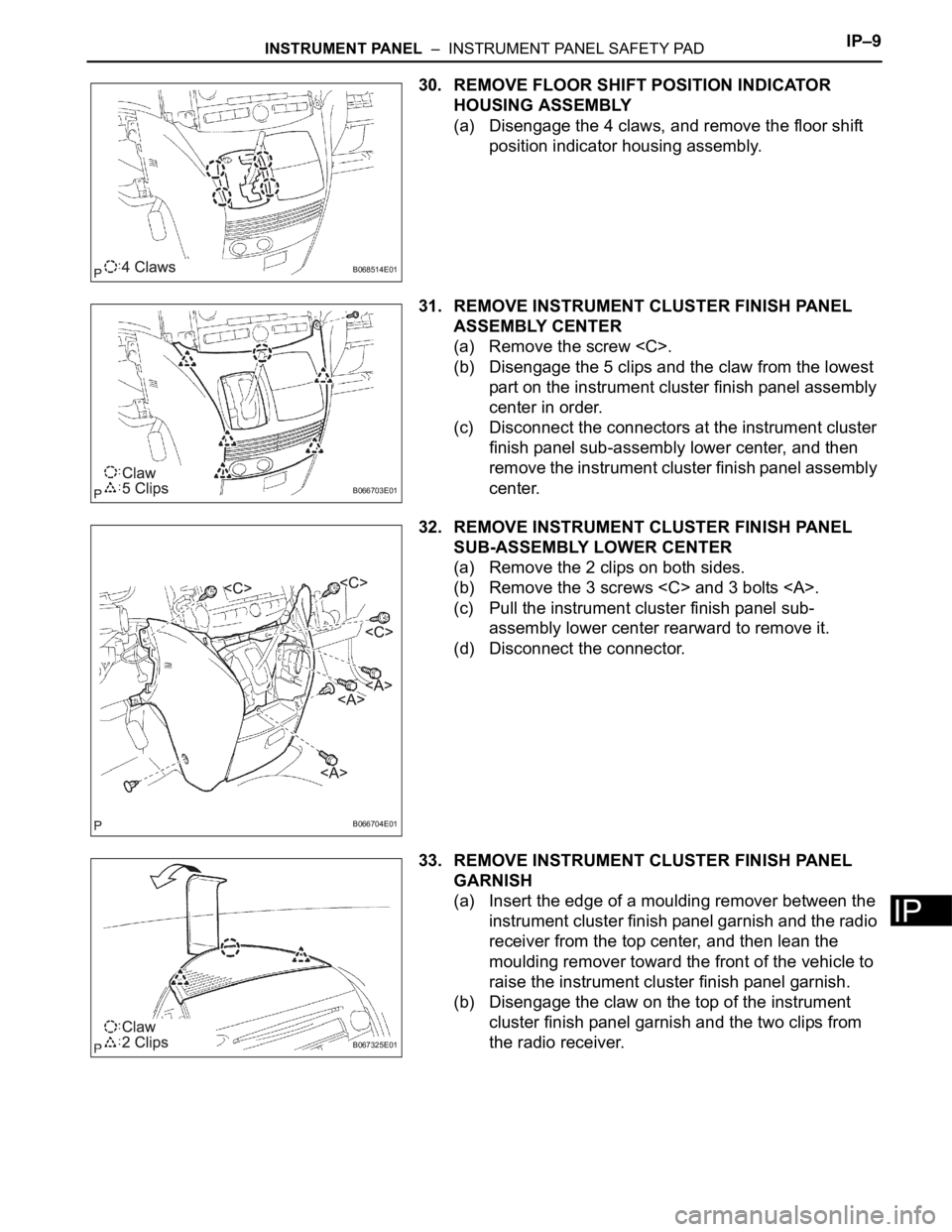
30. REMOVE FLOOR SHIFT POSITION INDICATOR
HOUSING ASSEMBLY
(a) Disengage the 4 claws, and remove the floor shift
position indicator housing assembly.
31. REMOVE INSTRUMENT CLUSTER FINISH PANEL
ASSEMBLY CENTER
(a) Remove the screw
(b) Disengage the 5 clips and the claw from the lowest
part on the instrument cluster finish panel assembly
center in order.
(c) Disconnect the connectors at the instrument cluster
finish panel sub-assembly lower center, and then
remove the instrument cluster finish panel assembly
center.
32. REMOVE INSTRUMENT CLUSTER FINISH PANEL
SUB-ASSEMBLY LOWER CENTER
(a) Remove the 2 clips on both sides.
(b) Remove the 3 screws
(c) Pull the instrument cluster finish panel sub-
assembly lower center rearward to remove it.
(d) Disconnect the connector.
33. REMOVE INSTRUMENT CLUSTER FINISH PANEL
GARNISH
(a) Insert the edge of a moulding remover between the
instrument cluster finish panel garnish and the radio
receiver from the top center, and then lean the
moulding remover toward the front of the vehicle to
raise the instrument cluster finish panel garnish.
(b) Disengage the claw on the top of the instrument
cluster finish panel garnish and the two clips from
the radio receiver.
B068514E01
B066703E01
B066704E01
B067325E01
Page 299 of 3000
SEAT – FRONT POWER SEAT CONTROL SYSTEMSE–7
SE
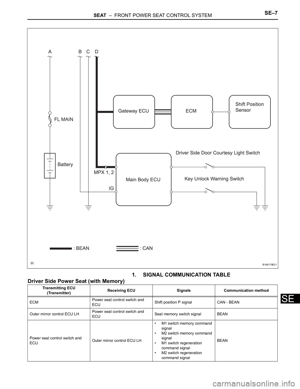
1. SIGNAL COMMUNICATION TABLE
Driver Side Power Seat (with Memory)
B168179E01
Transmitting ECU
(Transmitter)Receiving ECU Signals Communication method
ECMPower seat control switch and
ECUShift position P signal CAN - BEAN
Outer mirror control ECU LHPower seat control switch and
ECUSeat memory switch signal BEAN
Power seat control switch and
ECUOuter mirror control ECU LH• M1 switch memory command
signal
• M2 switch memory command
signal
• M1 switch regeneration
command signal
• M2 switch regeneration
command signalBEAN
Page 320 of 3000
ES–2522GR-FE ENGINE CONTROL SYSTEM – SFI SYSTEM
ES
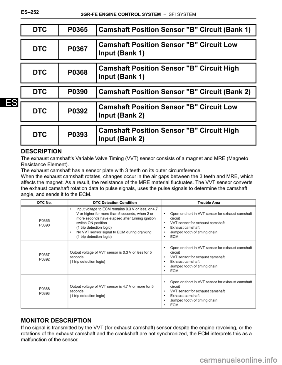
DESCRIPTION
The exhaust camshaft's Variable Valve Timing (VVT) sensor consists of a magnet and MRE (Magneto
Resistance Element).
The exhaust camshaft has a sensor plate with 3 teeth on its outer circumference.
When the exhaust camshaft rotates, changes occur in the air gaps between the 3 teeth and MRE, which
affects the magnet. As a result, the resistance of the MRE material fluctuates. The VVT sensor converts
the exhaust camshaft rotation data to pulse signals, uses the pulse signals to determine the camshaft
angle, and sends it to the ECM.
MONITOR DESCRIPTION
If no signal is transmitted by the VVT (for exhaust camshaft) sensor despite the engine revolving, or the
rotations of the exhaust camshaft and the crankshaft are not synchronized, the ECM interprets this as a
malfunction of the sensor.
DTC P0365 Camshaft Position Sensor "B" Circuit (Bank 1)
DTC P0367Camshaft Position Sensor "B" Circuit Low
Input (Bank 1)
DTC P0368Camshaft Position Sensor "B" Circuit High
Input (Bank 1)
DTC P0390 Camshaft Position Sensor "B" Circuit (Bank 2)
DTC P0392Camshaft Position Sensor "B" Circuit Low
Input (Bank 2)
DTC P0393Camshaft Position Sensor "B" Circuit High
Input (Bank 2)
DTC No. DTC Detection Condition Trouble Area
P0365
P0390• Input voltage to ECM remains 0.3 V or less, or 4.7
V or higher for more than 5 seconds, when 2 or
more seconds have elapsed after turning ignition
switch ON position
(1 trip detection logic)
• No VVT sensor signal to ECM during cranking
(1 trip detection logic)• Open or short in VVT sensor for exhaust camshaft
circuit
• VVT sensor for exhaust camshaft
• Exhaust camshaft
• Jumped tooth of timing chain
•ECM
P0367
P0392Output voltage of VVT sensor is 0.3 V or less for 5
seconds
(1 trip detection logic)• Open or short in VVT sensor for exhaust camshaft
circuit
• VVT sensor for exhaust camshaft
• Exhaust camshaft
• Jumped tooth of timing chain
•ECM
P0368
P0393Output voltage of VVT sensor is 4.7 V or more for 5
seconds
(1 trip detection logic)• Open or short in VVT sensor for exhaust camshaft
circuit
• VVT sensor for exhaust camshaft
• Exhaust camshaft
• Jumped tooth of timing chain
•ECM
Page 324 of 3000
ES–2562GR-FE ENGINE CONTROL SYSTEM – SFI SYSTEM
ES
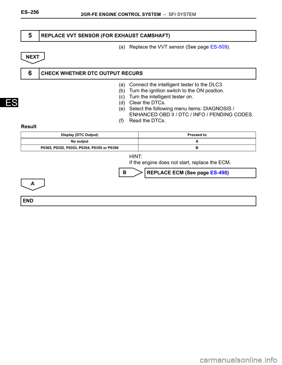
(a) Replace the VVT sensor (See page ES-509).
NEXT
(a) Connect the intelligent tester to the DLC3.
(b) Turn the ignition switch to the ON position.
(c) Turn the intelligent tester on.
(d) Clear the DTCs.
(e) Select the following menu items: DIAGNOSIS /
ENHANCED OBD II / DTC / INFO / PENDING CODES.
(f) Read the DTCs.
Result
HINT:
If the engine does not start, replace the ECM.
B
A
5REPLACE VVT SENSOR (FOR EXHAUST CAMSHAFT)
6CHECK WHETHER DTC OUTPUT RECURS
Display (DTC Output) Proceed to
No output A
P0365, P0352, P0353, P0354, P0355 or P0356 B
REPLACE ECM (See page ES-498)
END
Page 326 of 3000
ES–2582GR-FE ENGINE CONTROL SYSTEM – SFI SYSTEM
ES
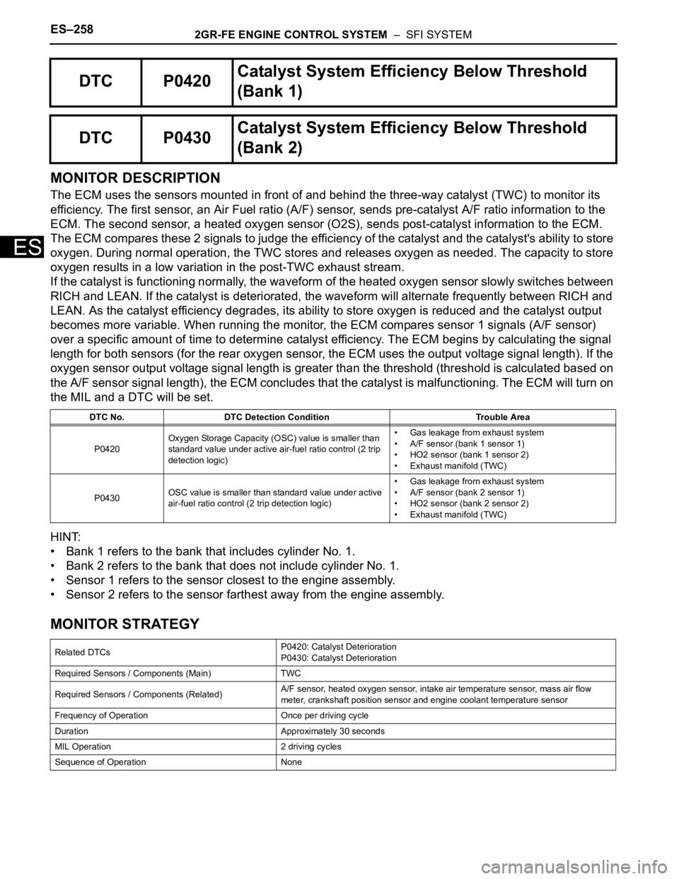
MONITOR DESCRIPTION
The ECM uses the sensors mounted in front of and behind the three-way catalyst (TWC) to monitor its
efficiency. The first sensor, an Air Fuel ratio (A/F) sensor, sends pre-catalyst A/F ratio information to the
ECM. The second sensor, a heated oxygen sensor (O2S), sends post-catalyst information to the ECM.
The ECM compares these 2 signals to judge the efficiency of the catalyst and the catalyst's ability to store
oxygen. During normal operation, the TWC stores and releases oxygen as needed. The capacity to store
oxygen results in a low variation in the post-TWC exhaust stream.
If the catalyst is functioning normally, the waveform of the heated oxygen sensor slowly switches between
RICH and LEAN. If the catalyst is deteriorated, the waveform will alternate frequently between RICH and
LEAN. As the catalyst efficiency degrades, its ability to store oxygen is reduced and the catalyst output
becomes more variable. When running the monitor, the ECM compares sensor 1 signals (A/F sensor)
over a specific amount of time to determine catalyst efficiency. The ECM begins by calculating the signal
length for both sensors (for the rear oxygen sensor, the ECM uses the output voltage signal length). If the
oxygen sensor output voltage signal length is greater than the threshold (threshold is calculated based on
the A/F sensor signal length), the ECM concludes that the catalyst is malfunctioning. The ECM will turn on
the MIL and a DTC will be set.
HINT:
• Bank 1 refers to the bank that includes cylinder No. 1.
• Bank 2 refers to the bank that does not include cylinder No. 1.
• Sensor 1 refers to the sensor closest to the engine assembly.
• Sensor 2 refers to the sensor farthest away from the engine assembly.
MONITOR STRATEGY
DTC P0420Catalyst System Efficiency Below Threshold
(Bank 1)
DTC P0430Catalyst System Efficiency Below Threshold
(Bank 2)
DTC No. DTC Detection Condition Trouble Area
P0420Oxygen Storage Capacity (OSC) value is smaller than
standard value under active air-fuel ratio control (2 trip
detection logic)• Gas leakage from exhaust system
• A/F sensor (bank 1 sensor 1)
• HO2 sensor (bank 1 sensor 2)
• Exhaust manifold (TWC)
P0430OSC value is smaller than standard value under active
air-fuel ratio control (2 trip detection logic)• Gas leakage from exhaust system
• A/F sensor (bank 2 sensor 1)
• HO2 sensor (bank 2 sensor 2)
• Exhaust manifold (TWC)
Related DTCsP0420: Catalyst Deterioration
P0430: Catalyst Deterioration
Required Sensors / Components (Main) TWC
Required Sensors / Components (Related)A/F sensor, heated oxygen sensor, intake air temperature sensor, mass air flow
meter, crankshaft position sensor and engine coolant temperature sensor
Frequency of Operation Once per driving cycle
Duration Approximately 30 seconds
MIL Operation 2 driving cycles
Sequence of Operation None
Page 327 of 3000
2GR-FE ENGINE CONTROL SYSTEM – SFI SYSTEMES–259
ES
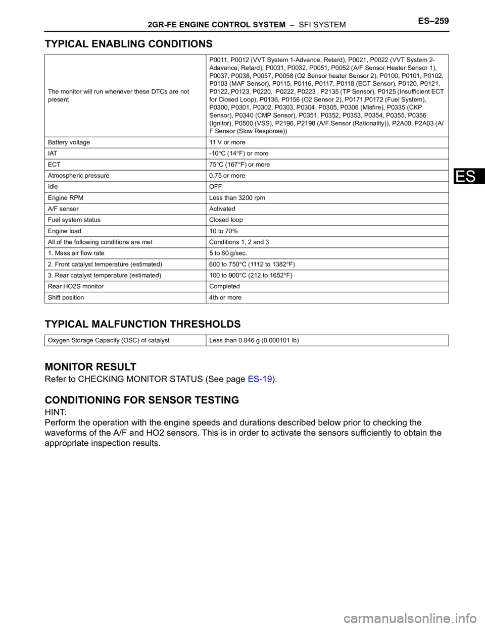
TYPICAL ENABLING CONDITIONS
TYPICAL MALFUNCTION THRESHOLDS
MONITOR RESULT
Refer to CHECKING MONITOR STATUS (See page ES-19).
CONDITIONING FOR SENSOR TESTING
HINT:
Perform the operation with the engine speeds and durations described below prior to checking the
waveforms of the A/F and HO2 sensors. This is in order to activate the sensors sufficiently to obtain the
appropriate inspection results.
The monitor will run whenever these DTCs are not
presentP0011, P0012 (VVT System 1-Advance, Retard), P0021, P0022 (VVT System 2-
Adavance, Retard), P0031, P0032, P0051, P0052 (A/F Sensor Heater Sensor 1),
P0037, P0038, P0057, P0058 (O2 Sensor heater Sensor 2), P0100, P0101, P0102,
P0103 (MAF Sensor), P0115, P0116, P0117, P0118 (ECT Sensor), P0120, P0121,
P0122, P0123, P0220, P0222, P0223 , P2135 (TP Sensor), P0125 (Insufficient ECT
for Closed Loop), P0136, P0156 (O2 Sensor 2), P0171,P0172 (Fuel System),
P0300, P0301, P0302, P0303, P0304, P0305, P0306 (Misfire), P0335 (CKP
Sensor), P0340 (CMP Sensor), P0351, P0352, P0353, P0354, P0355, P0356
(Ignitor), P0500 (VSS), P2196, P2198 (A/F Sensor (Rationality)), P2A00, P2A03 (A/
F Sensor (Slow Response))
Battery voltage 11 V or more
IAT -10
C (14F) or more
ECT 75
C (167F) or more
Atmospheric pressure 0.75 or more
Idle OFF
Engine RPM Less than 3200 rpm
A/F sensor Activated
Fuel system status Closed loop
Engine load 10 to 70%
All of the following conditions are met Conditions 1, 2 and 3
1. Mass air flow rate 5 to 60 g/sec.
2. Front catalyst temperature (estimated) 600 to 750
C (1112 to 1382F)
3. Rear catalyst temperature (estimated) 100 to 900
C (212 to 1652F)
Rear HO2S monitor Completed
Shift position 4th or more
Oxygen Storage Capacity (OSC) of catalyst Less than 0.046 g (0.000101 lb)
Page 331 of 3000
2GR-FE ENGINE CONTROL SYSTEM – SFI SYSTEMES–263
ES
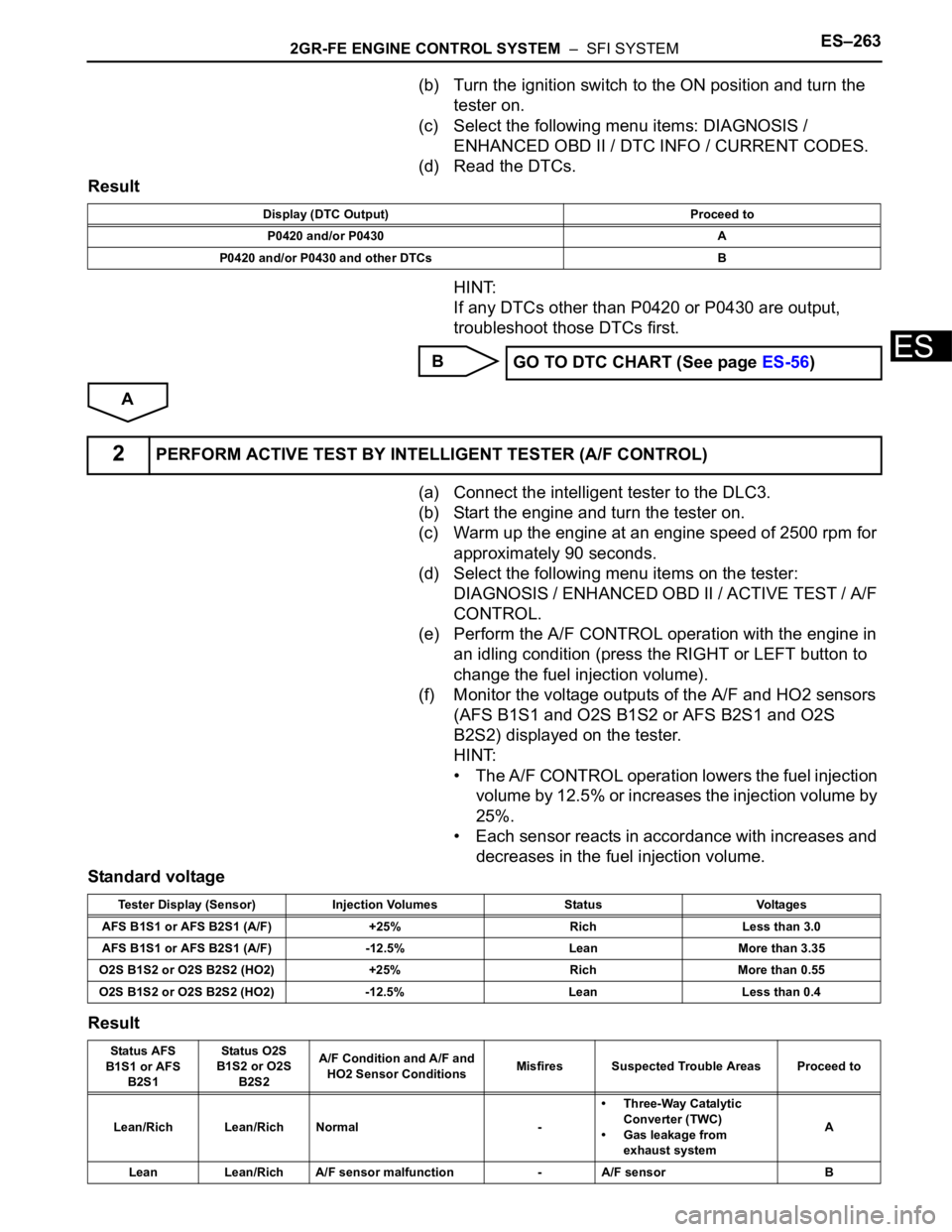
(b) Turn the ignition switch to the ON position and turn the
tester on.
(c) Select the following menu items: DIAGNOSIS /
ENHANCED OBD II / DTC INFO / CURRENT CODES.
(d) Read the DTCs.
Result
HINT:
If any DTCs other than P0420 or P0430 are output,
troubleshoot those DTCs first.
B
A
(a) Connect the intelligent tester to the DLC3.
(b) Start the engine and turn the tester on.
(c) Warm up the engine at an engine speed of 2500 rpm for
approximately 90 seconds.
(d) Select the following menu items on the tester:
DIAGNOSIS / ENHANCED OBD II / ACTIVE TEST / A/F
CONTROL.
(e) Perform the A/F CONTROL operation with the engine in
an idling condition (press the RIGHT or LEFT button to
change the fuel injection volume).
(f) Monitor the voltage outputs of the A/F and HO2 sensors
(AFS B1S1 and O2S B1S2 or AFS B2S1 and O2S
B2S2) displayed on the tester.
HINT:
• The A/F CONTROL operation lowers the fuel injection
volume by 12.5% or increases the injection volume by
25%.
• Each sensor reacts in accordance with increases and
decreases in the fuel injection volume.
Standard voltage
Result
Display (DTC Output) Proceed to
P0420 and/or P0430 A
P0420 and/or P0430 and other DTCs B
GO TO DTC CHART (See page ES-56)
2PERFORM ACTIVE TEST BY INTELLIGENT TESTER (A/F CONTROL)
Tester Display (Sensor) Injection Volumes Status Voltages
AFS B1S1 or AFS B2S1 (A/F) +25% Rich Less than 3.0
AFS B1S1 or AFS B2S1 (A/F) -12.5% Lean More than 3.35
O2S B1S2 or O2S B2S2 (HO2) +25% Rich More than 0.55
O2S B1S2 or O2S B2S2 (HO2) -12.5% Lean Less than 0.4
Status AFS
B1S1 or AFS
B2S1Status O2S
B1S2 or O2S
B2S2A/F Condition and A/F and
HO2 Sensor ConditionsMisfires Suspected Trouble Areas Proceed to
Lean/Rich Lean/Rich Normal -• Three-Way Catalytic
Converter (TWC)
• Gas leakage from
exhaust systemA
Lean Lean/Rich A/F sensor malfunction - A/F sensor B