Position TOYOTA SIENNA 2007 Service Owner's Manual
[x] Cancel search | Manufacturer: TOYOTA, Model Year: 2007, Model line: SIENNA, Model: TOYOTA SIENNA 2007Pages: 3000, PDF Size: 52.26 MB
Page 224 of 3000
SERVICE SPECIFICATIONS – U151F AUTOMATIC TRANSAXLESS–31
SS
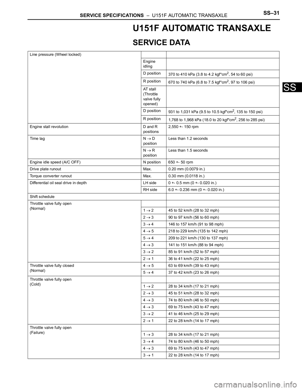
U151F AUTOMATIC TRANSAXLE
SERVICE DATA
Line pressure (Wheel locked)
Engine
idling
D position
370 to 410 kPa (3.8 to 4.2 kgf*cm
2, 54 to 60 psi)
R position
670 to 740 kPa (6.8 to 7.5 kgf*cm
2, 97 to 106 psi)
AT s t a l l
(Throttle
valve fully
opened)
D position
931 to 1,031 kPa (9.5 to 10.5 kgf*cm
2, 135 to 150 psi)
R position
1,768 to 1,968 kPa (18.0 to 20 kgf*cm
2, 256 to 285 psi)
Engine stall revolution D and R
positions2,550 +- 150 rpm
Time lag N
D
positionLess than 1.2 seconds
N
R
positionLess than 1.5 seconds
Engine idle speed (A/C OFF) N position 650 +- 50 rpm
Drive plate runout Max. 0.20 mm (0.0079 in.)
Torque converter runout Max. 0.30 mm (0.0118 in.)
Differential oil seal drive in depth LH side 0 +- 0.5 mm (0 +- 0.020 in.)
RH side 6.0 +- 0.236 mm (0 +- 0.020 in.)
Shift schedule
Throttle valve fully open
(Normal)
1
2 45 to 52 km/h (28 to 32 mph)
2
3 90 to 97 km/h (56 to 60 mph)
3
4 146 to 157 km/h (91 to 98 mph)
4
5 218 to 229 km/h (135 to 142 mph)
5
4 209 to 221 km/h (130 to 137 mph)
4
3 141 to 151 km/h (88 to 94 mph)
3
2 85 to 91 km/h (52 to 57 mph)
2
1 36 to 41 km/h (22 to 25 mph)
Throttle valve fully closed
(Normal)4
5 63 to 69 km/h (39 to 43 mph)
5
4 37 to 42 km/h (23 to 26 mph)
Throttle valve fully open
(Cold)
1
2 28 to 34 km/h (17 to 21 mph)
2
3 45 to 51 km/h (28 to 32 mph)
4
3 74 to 80 km/h (46 to 50 mph)
4
3 69 to 75 km/h (43 to 47 mph)
3
2 41 to 46 km/h (25 to 29 mph)
2
1 22 to 28 km/h (14 to 17 mph)
Throttle valve fully open
(Failure)
1
3 28 to 34 km/h (17 to 21 mph)
3
4 74 to 80 km/h (46 to 50 mph)
4
3 69 to 75 km/h (43 to 47 mph)
3
1 22 to 28 km/h (14 to 17 mph)
Page 250 of 3000
WW–6WIPER AND WASHER – FRONT WIPER MOTOR
WW
INSTALLATION
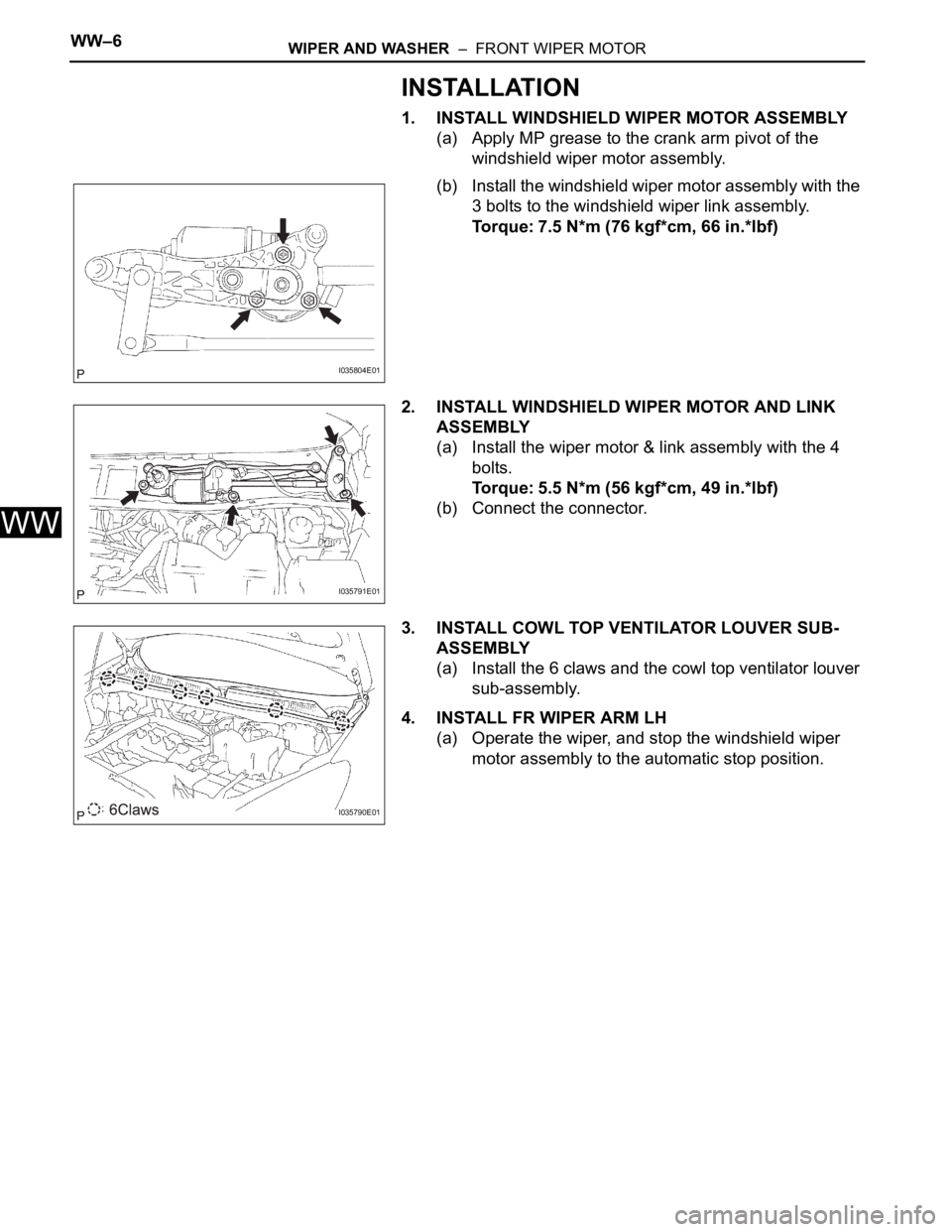
1. INSTALL WINDSHIELD WIPER MOTOR ASSEMBLY
(a) Apply MP grease to the crank arm pivot of the
windshield wiper motor assembly.
(b) Install the windshield wiper motor assembly with the
3 bolts to the windshield wiper link assembly.
Torque: 7.5 N*m (76 kgf*cm, 66 in.*lbf)
2. INSTALL WINDSHIELD WIPER MOTOR AND LINK
ASSEMBLY
(a) Install the wiper motor & link assembly with the 4
bolts.
Torque: 5.5 N*m (56 kgf*cm, 49 in.*lbf)
(b) Connect the connector.
3. INSTALL COWL TOP VENTILATOR LOUVER SUB-
ASSEMBLY
(a) Install the 6 claws and the cowl top ventilator louver
sub-assembly.
4. INSTALL FR WIPER ARM LH
(a) Operate the wiper, and stop the windshield wiper
motor assembly to the automatic stop position.
I035804E01
I035791E01
I035790E01
Page 251 of 3000
WIPER AND WASHER – FRONT WIPER MOTORWW–7
WW
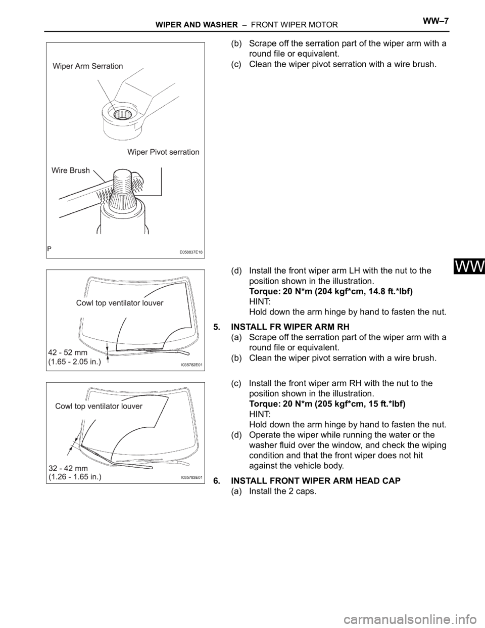
(b) Scrape off the serration part of the wiper arm with a
round file or equivalent.
(c) Clean the wiper pivot serration with a wire brush.
(d) Install the front wiper arm LH with the nut to the
position shown in the illustration.
Torque: 20 N*m (204 kgf*cm, 14.8 ft.*lbf)
HINT:
Hold down the arm hinge by hand to fasten the nut.
5. INSTALL FR WIPER ARM RH
(a) Scrape off the serration part of the wiper arm with a
round file or equivalent.
(b) Clean the wiper pivot serration with a wire brush.
(c) Install the front wiper arm RH with the nut to the
position shown in the illustration.
Torque: 20 N*m (205 kgf*cm, 15 ft.*lbf)
HINT:
Hold down the arm hinge by hand to fasten the nut.
(d) Operate the wiper while running the water or the
washer fluid over the window, and check the wiping
condition and that the front wiper does not hit
against the vehicle body.
6. INSTALL FRONT WIPER ARM HEAD CAP
(a) Install the 2 caps.
E058837E18
I035782E01
I035783E01
Page 265 of 3000
NS–4NAVIGATION – NAVIGATION SYSTEM
NS
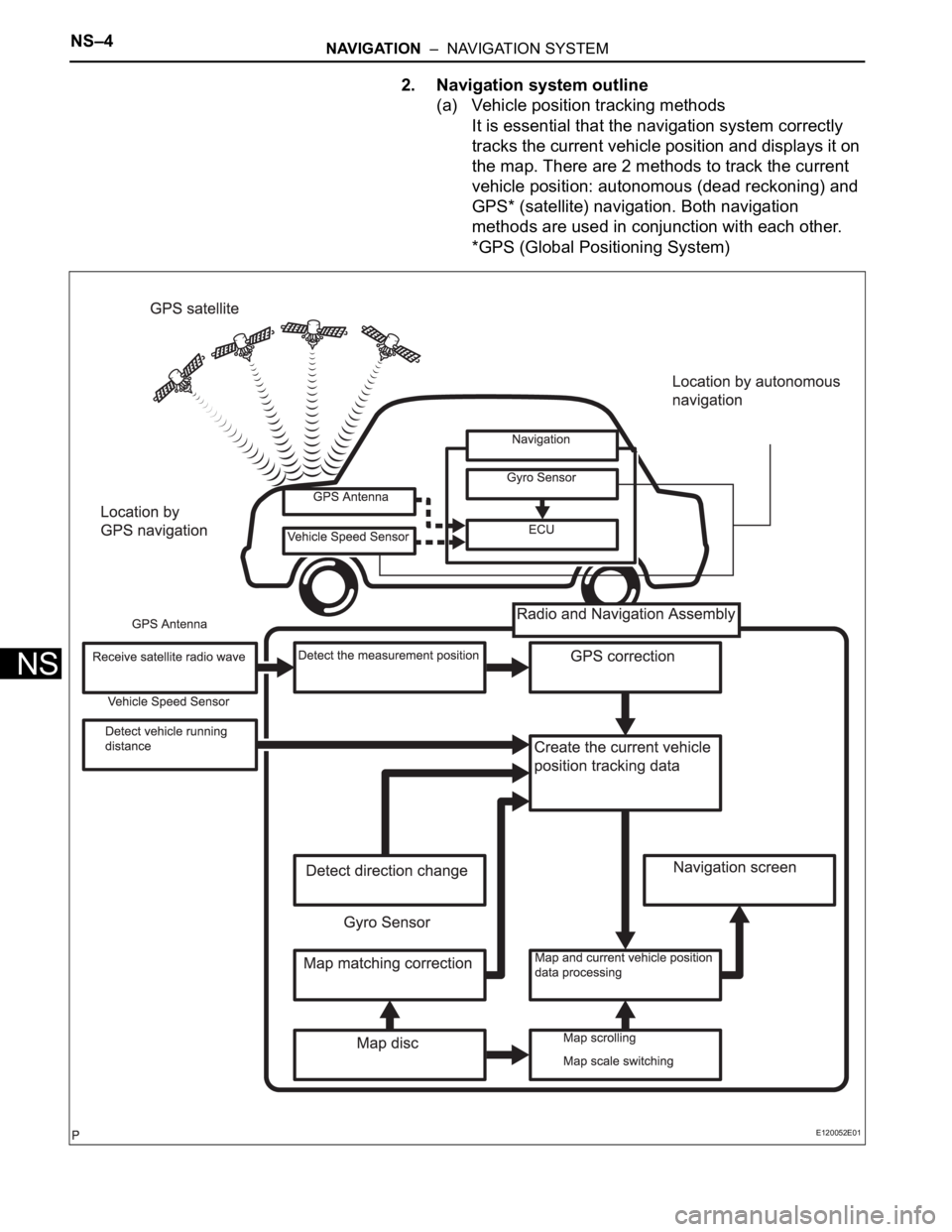
2. Navigation system outline
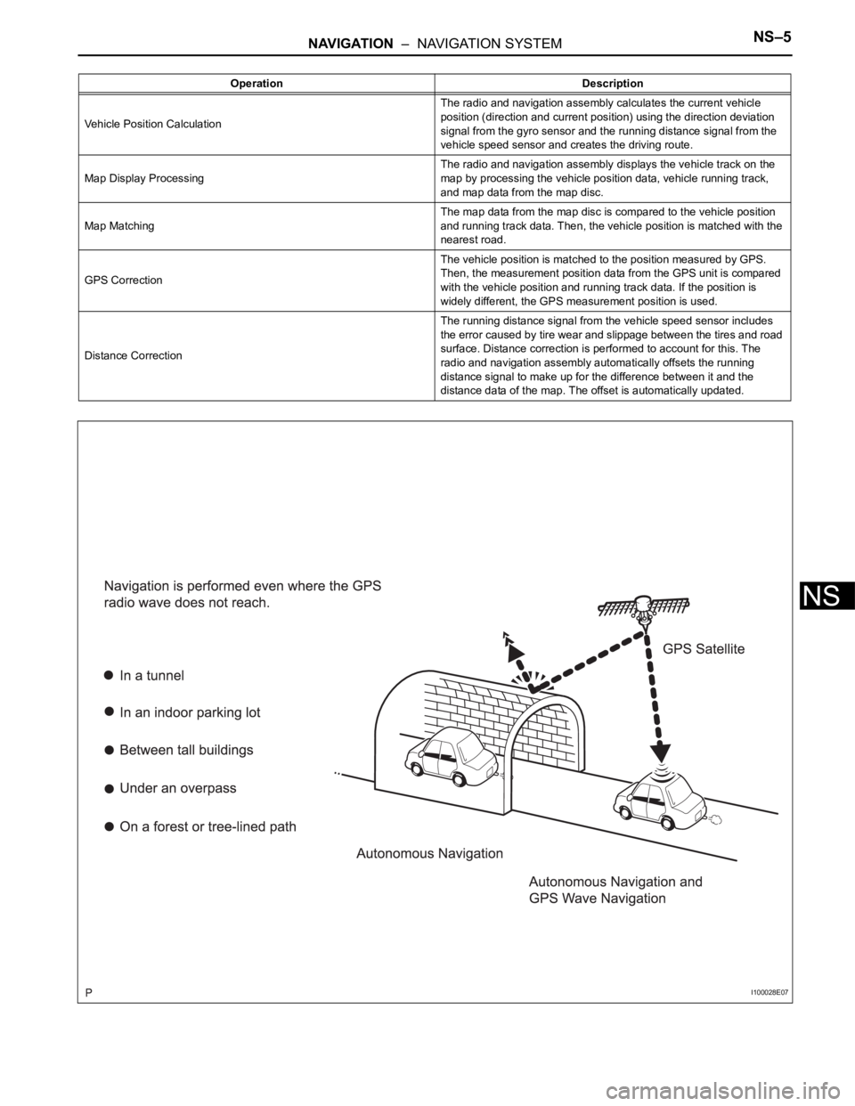
(a) Vehicle position tracking methods
It is essential that the navigation system correctly
tracks the current vehicle position and displays it on
the map. There are 2 methods to track the current
vehicle position: autonomous (dead reckoning) and
GPS* (satellite) navigation. Both navigation
methods are used in conjunction with each other.
*GPS (Global Positioning System)
E120052E01
Page 266 of 3000
NAVIGATION – NAVIGATION SYSTEMNS–5
NS
Operation Description
Vehicle Position CalculationThe radio and navigation assembly calculates the current vehicle
position (direction and current position) using the direction deviation
signal from the gyro sensor and the running distance signal from the
vehicle speed sensor and creates the driving route.
Map Display ProcessingThe radio and navigation assembly displays the vehicle track on the
map by processing the vehicle position data, vehicle running track,
and map data from the map disc.
Map MatchingThe map data from the map disc is compared to the vehicle position
and running track data. Then, the vehicle position is matched with the
nearest road.
GPS CorrectionThe vehicle position is matched to the position measured by GPS.
Then, the measurement position data from the GPS unit is compared
with the vehicle position and running track data. If the position is
widely different, the GPS measurement position is used.
Distance CorrectionThe running distance signal from the vehicle speed sensor includes
the error caused by tire wear and slippage between the tires and road
surface. Distance correction is performed to account for this. The
radio and navigation assembly automatically offsets the running
distance signal to make up for the difference between it and the
distance data of the map. The offset is automatically updated.
I100028E07
Page 267 of 3000
NS–6NAVIGATION – NAVIGATION SYSTEM
NS
HINT:
The combination of autonomous and GPS
navigation makes it possible to display the vehicle
position even when the vehicle is in places where
the GPS radio wave cannot receive a signal. When
only autonomous navigation is used, however, the
mapping accuracy may slightly decline.
(b) Autonomous navigation
This method determines the relative vehicle position
based on the running track determined by the gyro
and vehicle speed sensors located in the radio and
navigation assembly.
(1) Gyro sensor
Calculates the direction by detecting angular
velocity. It is located in the radio and navigation
assembly.
(2) Vehicle speed sensor
Used to calculate the vehicle running distance.
Page 268 of 3000
NAVIGATION – NAVIGATION SYSTEMNS–7
NS
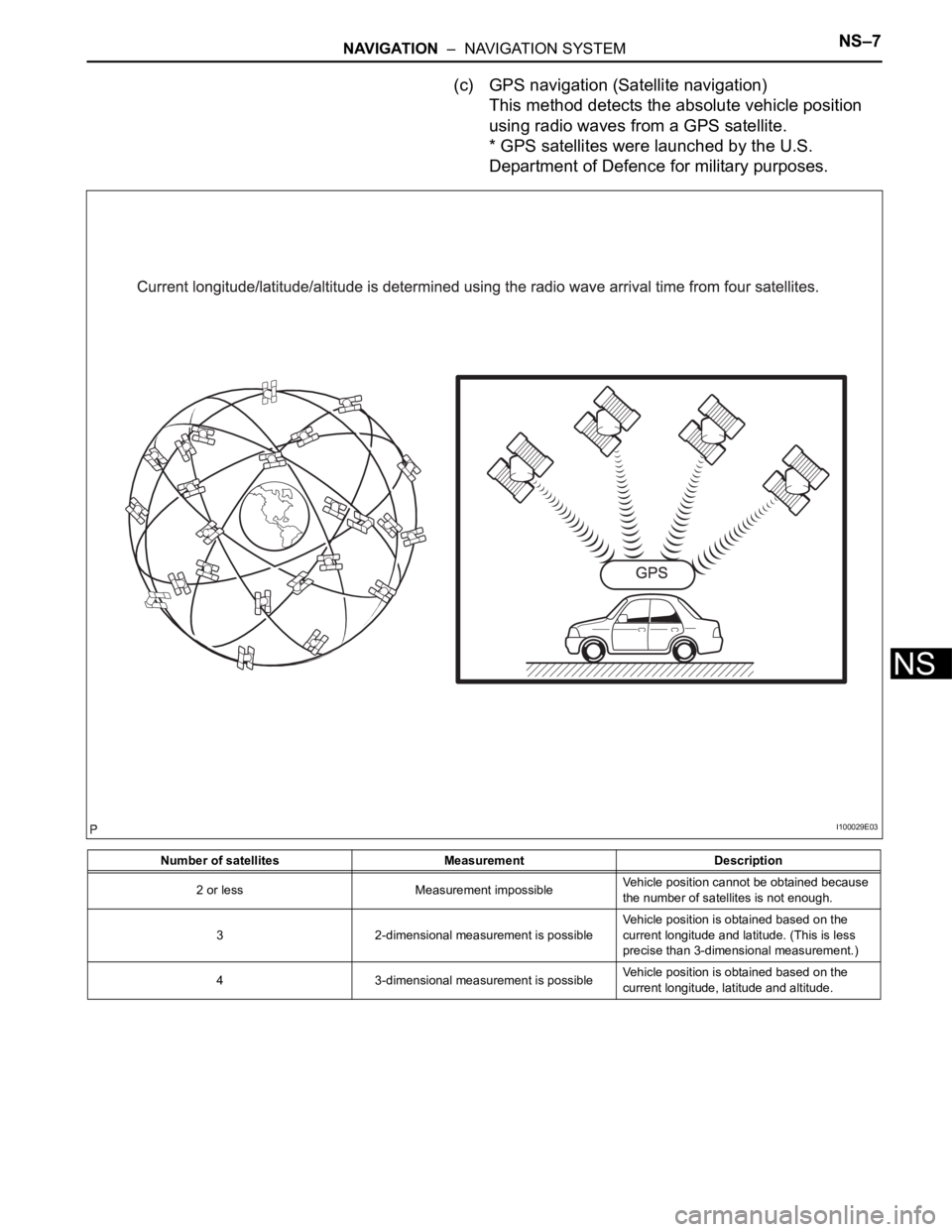
(c) GPS navigation (Satellite navigation)
This method detects the absolute vehicle position
using radio waves from a GPS satellite.
* GPS satellites were launched by the U.S.
Department of Defence for military purposes.
Number of satellites Measurement Description
2 or less Measurement impossibleVehicle position cannot be obtained because
the number of satellites is not enough.
3 2-dimensional measurement is possibleVehicle position is obtained based on the
current longitude and latitude. (This is less
precise than 3-dimensional measurement.)
4 3-dimensional measurement is possibleVehicle position is obtained based on the
current longitude, latitude and altitude.
I100029E03
Page 269 of 3000
NS–8NAVIGATION – NAVIGATION SYSTEM
NS
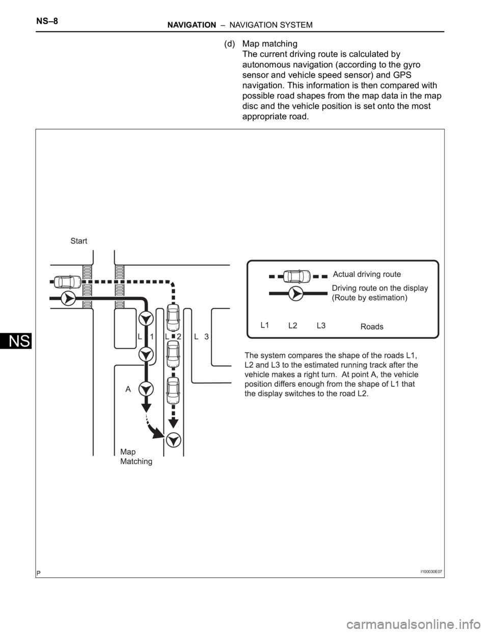
(d) Map matching
The current driving route is calculated by
autonomous navigation (according to the gyro
sensor and vehicle speed sensor) and GPS
navigation. This information is then compared with
possible road shapes from the map data in the map
disc and the vehicle position is set onto the most
appropriate road.
I100030E07
Page 270 of 3000
NAVIGATION – NAVIGATION SYSTEMNS–9
NS
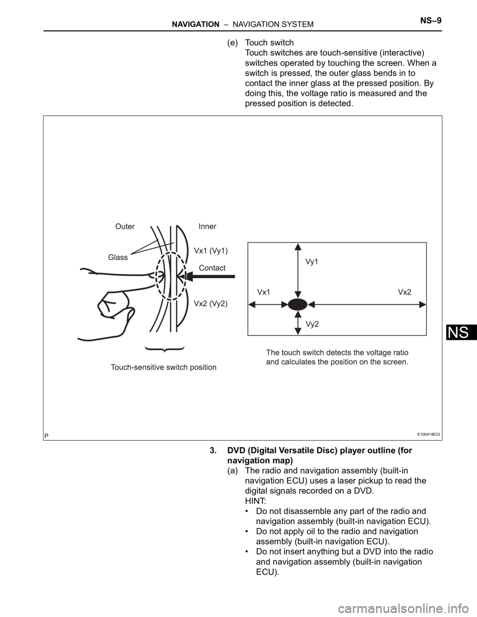
(e) Touch switch
Touch switches are touch-sensitive (interactive)
switches operated by touching the screen. When a
switch is pressed, the outer glass bends in to
contact the inner glass at the pressed position. By
doing this, the voltage ratio is measured and the
pressed position is detected.
3. DVD (Digital Versatile Disc) player outline (for
navigation map)
(a) The radio and navigation assembly (built-in
navigation ECU) uses a laser pickup to read the
digital signals recorded on a DVD.
HINT:
• Do not disassemble any part of the radio and
navigation assembly (built-in navigation ECU).
• Do not apply oil to the radio and navigation
assembly (built-in navigation ECU).
• Do not insert anything but a DVD into the radio
and navigation assembly (built-in navigation
ECU).
E106414E03
Page 277 of 3000

PARK ASSIST / MONITORING – REAR VIEW MONITOR SYSTEMPM–3
PM
SYSTEM DESCRIPTION
1. GENERAL
(a) To assist the driver with parking the vehicle by
displaying an image of the area behind the vehicle,
this system has a television camera mounted on the
luggage compartment door. The system displays
the image on the radio and navigation assembly.
(b) This system consists of the following components:
(1) Radio and navigation assembly
(2) Television camera assembly
(c) This system is equipped with a self-diagnosis
system, which is operated on a dedicated window
that appears on the display panel, just as in the
navigation system.
2. FUNCTION OF COMPONENTS
(a) The radio and navigation assembly controls the
system by using information from the following
components:
3. OPERATION EXPLANATION
(a) The radio and navigation assembly receives the R
position signal from the park / neutral position switch
when the shift lever is moved to the R position. After
receiving the R position signal, the radio and
navigation assembly switches from the navigation
system to the rear view monitor system.
4. NOTES FOR REAR VIEW MONITOR
(a) Notes for the rear view monitor.
(1) The rear view monitor may not function properly
if subjected to a severe blow by any hard object.
(2) Do not "scrub" the cover part of the camera
(resin made). Scrubbing it may scratch the cover
and affect the image. Prevent organic solvents,
waxes, bond removing solvents, or glass coating
from adhering to the cover. Clean it off
immediately, and wash with water.
(3) Exposing the camera to a sudden temperature
change may affect proper functioning of the
camera.
(4) A clear image may not appear if the camera is
dirty with snow, mud, etc. In that case, wash it
with water and wipe off the lens. Use a detergent
to remove dirt if necessary.
Item Function
Television Camera Assembly• Mounted on the luggage compartment door to transmit the rear
view of the vehicle to the radio and navigation assembly.
• A color video camera that uses a CCD (Charge Coupled Device)
and a wide-angle lens.
Radio and Navigation Assembly• Transmits video signals, which contain an image of the area
behind the vehicle taken with the television camera assembly.
• Radio and navigation assembly effects control of the system by
receiving the shift position signal from park/neutral position switch.
• Displays the rear view monitor image on the display panel.
Park/Neutral Position SwitchTransmits a reverse shift position signal to the radio and navigation
assembly.