TOYOTA SIENNA 2007 Service Repair Manual
Manufacturer: TOYOTA, Model Year: 2007, Model line: SIENNA, Model: TOYOTA SIENNA 2007Pages: 3000, PDF Size: 52.26 MB
Page 851 of 3000
MP–8MULTIPLEX COMMUNICATION – MULTIPLEX COMMUNICATION SYSTEM
MP
(c) Measure the resistance between the specified
terminals on the wire harness side connector.
If the result is not as specified, there may be a
malfunction on the wire harness side.
4. SEAT POSITION CONTROL ECU (with Driving
Position Memory)
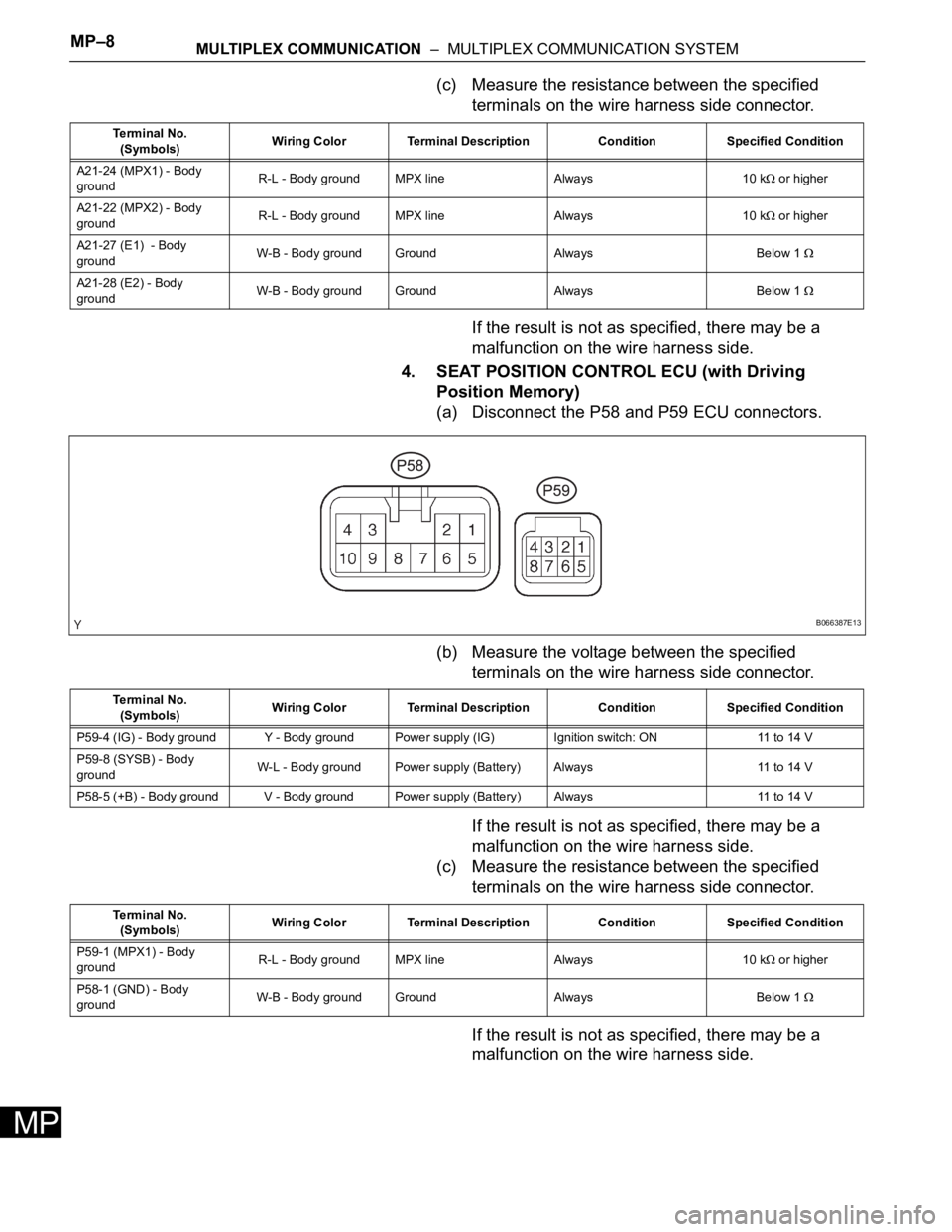
(a) Disconnect the P58 and P59 ECU connectors.
(b) Measure the voltage between the specified
terminals on the wire harness side connector.
If the result is not as specified, there may be a
malfunction on the wire harness side.
(c) Measure the resistance between the specified
terminals on the wire harness side connector.
If the result is not as specified, there may be a
malfunction on the wire harness side.
Te r m i n a l N o .
(Symbols)Wiring Color Terminal Description Condition Specified Condition
A21-24 (MPX1) - Body
groundR-L - Body ground MPX line Always 10 k
or higher
A21-22 (MPX2) - Body
groundR-L - Body ground MPX line Always 10 k
or higher
A21-27 (E1) - Body
groundW-B - Body ground Ground Always Below 1
A21-28 (E2) - Body
groundW-B - Body ground Ground Always Below 1
B066387E13
Te r m i n a l N o .
(Symbols)Wiring Color Terminal Description Condition Specified Condition
P59-4 (IG) - Body ground Y - Body ground Power supply (IG) Ignition switch: ON 11 to 14 V
P59-8 (SYSB) - Body
groundW-L - Body ground Power supply (Battery) Always 11 to 14 V
P58-5 (+B) - Body ground V - Body ground Power supply (Battery) Always 11 to 14 V
Te r m i n a l N o .
(Symbols)Wiring Color Terminal Description Condition Specified Condition
P59-1 (MPX1) - Body
groundR-L - Body ground MPX line Always 10 k
or higher
P58-1 (GND) - Body
groundW-B - Body ground Ground Always Below 1
Page 852 of 3000
MULTIPLEX COMMUNICATION – MULTIPLEX COMMUNICATION SYSTEMMP–9
MP
5. AIR CONDITIONING AMPLIFIER
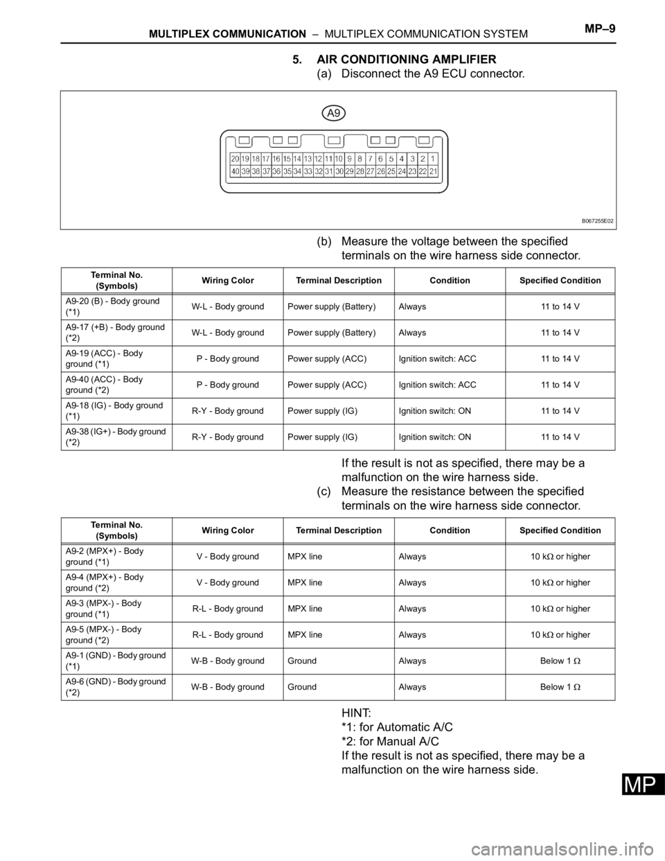
(a) Disconnect the A9 ECU connector.
(b) Measure the voltage between the specified
terminals on the wire harness side connector.
If the result is not as specified, there may be a
malfunction on the wire harness side.
(c) Measure the resistance between the specified
terminals on the wire harness side connector.
HINT:
*1: for Automatic A/C
*2: for Manual A/C
If the result is not as specified, there may be a
malfunction on the wire harness side.
B067255E02
Terminal No.
(Symbols)Wiring Color Terminal Description Condition Specified Condition
A9-20 (B) - Body ground
(*1)W-L - Body ground Power supply (Battery) Always 11 to 14 V
A9-17 (+B) - Body ground
(*2)W-L - Body ground Power supply (Battery) Always 11 to 14 V
A9-19 (ACC) - Body
ground (*1)P - Body ground Power supply (ACC) Ignition switch: ACC 11 to 14 V
A9-40 (ACC) - Body
ground (*2)P - Body ground Power supply (ACC) Ignition switch: ACC 11 to 14 V
A9-18 (IG) - Body ground
(*1)R-Y - Body ground Power supply (IG) Ignition switch: ON 11 to 14 V
A9-38 (IG+) - Body ground
(*2)R-Y - Body ground Power supply (IG) Ignition switch: ON 11 to 14 V
Terminal No.
(Symbols)Wiring Color Terminal Description Condition Specified Condition
A9-2 (MPX+) - Body
ground (*1)V - Body ground MPX line Always 10 k
or higher
A9-4 (MPX+) - Body
ground (*2)V - Body ground MPX line Always 10 k
or higher
A9-3 (MPX-) - Body
ground (*1)R-L - Body ground MPX line Always 10 k
or higher
A9-5 (MPX-) - Body
ground (*2)R-L - Body ground MPX line Always 10 k
or higher
A9-1 (GND) - Body ground
(*1)W-B - Body ground Ground Always Below 1
A9-6 (GND) - Body ground
(*2)W-B - Body ground Ground Always Below 1
Page 853 of 3000
MP–10MULTIPLEX COMMUNICATION – MULTIPLEX COMMUNICATION SYSTEM
MP
6. COMBINATION METER
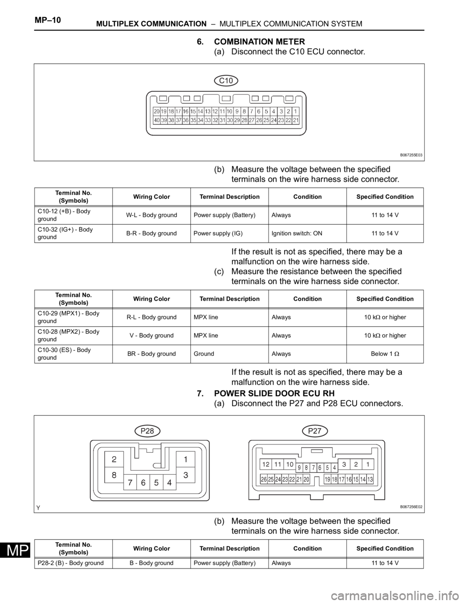
(a) Disconnect the C10 ECU connector.
(b) Measure the voltage between the specified
terminals on the wire harness side connector.
If the result is not as specified, there may be a
malfunction on the wire harness side.
(c) Measure the resistance between the specified
terminals on the wire harness side connector.
If the result is not as specified, there may be a
malfunction on the wire harness side.
7. POWER SLIDE DOOR ECU RH
(a) Disconnect the P27 and P28 ECU connectors.
(b) Measure the voltage between the specified
terminals on the wire harness side connector.
B067255E03
Te r m i n a l N o .
(Symbols)Wiring Color Terminal Description Condition Specified Condition
C10-12 (+B) - Body
groundW-L - Body ground Power supply (Battery) Always 11 to 14 V
C10-32 (IG+) - Body
groundB-R - Body ground Power supply (IG) Ignition switch: ON 11 to 14 V
Te r m i n a l N o .
(Symbols)Wiring Color Terminal Description Condition Specified Condition
C10-29 (MPX1) - Body
groundR-L - Body ground MPX line Always 10 k
or higher
C10-28 (MPX2) - Body
groundV - Body ground MPX line Always 10 k
or higher
C10-30 (ES) - Body
groundBR - Body ground Ground Always Below 1
B067256E02
Te r m i n a l N o .
(Symbols)Wiring Color Terminal Description Condition Specified Condition
P28-2 (B) - Body ground B - Body ground Power supply (Battery) Always 11 to 14 V
Page 854 of 3000
MULTIPLEX COMMUNICATION – MULTIPLEX COMMUNICATION SYSTEMMP–11
MP
If the result is not as specified, there may be a
malfunction on the wire harness side.
(c) Measure the resistance between the specified
terminals on the wire harness side connector.
If the result is not as specified, there may be a
malfunction on the wire harness side.
8. POWER SLIDE DOOR ECU LH
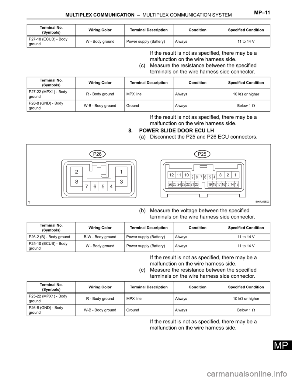
(a) Disconnect the P25 and P26 ECU connectors.
(b) Measure the voltage between the specified
terminals on the wire harness side connector.
If the result is not as specified, there may be a
malfunction on the wire harness side.
(c) Measure the resistance between the specified
terminals on the wire harness side connector.
If the result is not as specified, there may be a
malfunction on the wire harness side.
P27-10 (ECUB) - Body
groundW - Body ground Power supply (Battery) Always 11 to 14 V Terminal No.
(Symbols)Wiring Color Terminal Description Condition Specified Condition
Terminal No.
(Symbols)Wiring Color Terminal Description Condition Specified Condition
P27-22 (MPX1) - Body
groundR - Body ground MPX line Always 10 k
or higher
P28-8 (GND) - Body
groundW-B - Body ground Ground Always Below 1
B067256E03
Terminal No.
(Symbols)Wiring Color Terminal Description Condition Specified Condition
P26-2 (B) - Body ground B-W - Body ground Power supply (Battery) Always 11 to 14 V
P25-10 (ECUB) - Body
groundW - Body ground Power supply (Battery) Always 11 to 14 V
Terminal No.
(Symbols)Wiring Color Terminal Description Condition Specified Condition
P25-22 (MPX1) - Body
groundR - Body ground MPX line Always 10 k
or higher
P26-8 (GND) - Body
groundW-B - Body ground Ground Always Below 1
Page 855 of 3000
MP–12MULTIPLEX COMMUNICATION – MULTIPLEX COMMUNICATION SYSTEM
MP
9. POWER BACK DOOR ECU
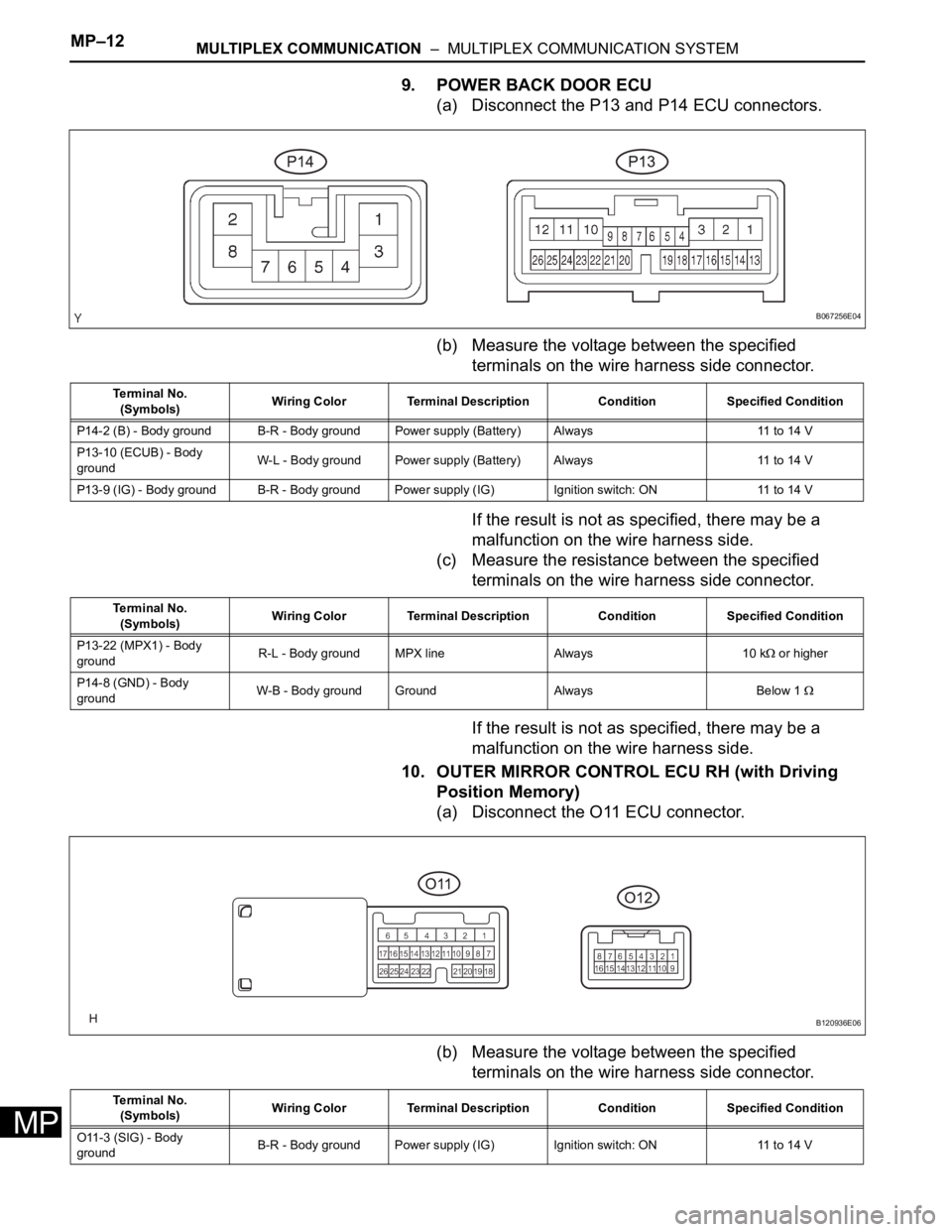
(a) Disconnect the P13 and P14 ECU connectors.
(b) Measure the voltage between the specified
terminals on the wire harness side connector.
If the result is not as specified, there may be a
malfunction on the wire harness side.
(c) Measure the resistance between the specified
terminals on the wire harness side connector.
If the result is not as specified, there may be a
malfunction on the wire harness side.
10. OUTER MIRROR CONTROL ECU RH (with Driving
Position Memory)
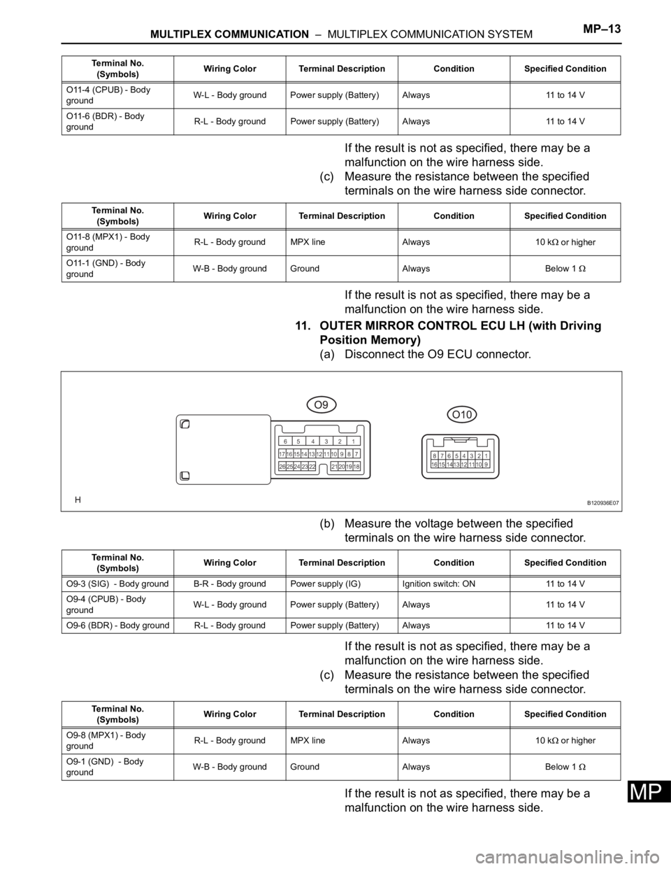
(a) Disconnect the O11 ECU connector.
(b) Measure the voltage between the specified
terminals on the wire harness side connector.
B067256E04
Te r m i n a l N o .
(Symbols)Wiring Color Terminal Description Condition Specified Condition
P14-2 (B) - Body ground B-R - Body ground Power supply (Battery) Always 11 to 14 V
P13-10 (ECUB) - Body
groundW-L - Body ground Power supply (Battery) Always 11 to 14 V
P13-9 (IG) - Body ground B-R - Body ground Power supply (IG) Ignition switch: ON 11 to 14 V
Te r m i n a l N o .
(Symbols)Wiring Color Terminal Description Condition Specified Condition
P13-22 (MPX1) - Body
groundR-L - Body ground MPX line Always 10 k
or higher
P14-8 (GND) - Body
groundW-B - Body ground Ground Always Below 1
B120936E06
Te r m i n a l N o .
(Symbols)Wiring Color Terminal Description Condition Specified Condition
O11-3 (SIG) - Body
groundB-R - Body ground Power supply (IG) Ignition switch: ON 11 to 14 V
Page 856 of 3000
MULTIPLEX COMMUNICATION – MULTIPLEX COMMUNICATION SYSTEMMP–13
MP
If the result is not as specified, there may be a
malfunction on the wire harness side.
(c) Measure the resistance between the specified
terminals on the wire harness side connector.
If the result is not as specified, there may be a
malfunction on the wire harness side.
11. OUTER MIRROR CONTROL ECU LH (with Driving
Position Memory)
(a) Disconnect the O9 ECU connector.
(b) Measure the voltage between the specified
terminals on the wire harness side connector.
If the result is not as specified, there may be a
malfunction on the wire harness side.
(c) Measure the resistance between the specified
terminals on the wire harness side connector.
If the result is not as specified, there may be a
malfunction on the wire harness side.
O11-4 (CPUB) - Body
groundW-L - Body ground Power supply (Battery) Always 11 to 14 V
O11-6 (BDR) - Body
groundR-L - Body ground Power supply (Battery) Always 11 to 14 V Terminal No.
(Symbols)Wiring Color Terminal Description Condition Specified Condition
Terminal No.
(Symbols)Wiring Color Terminal Description Condition Specified Condition
O11-8 (MPX1) - Body
groundR-L - Body ground MPX line Always 10 k
or higher
O11-1 (GND) - Body
groundW-B - Body ground Ground Always Below 1
B120936E07
Terminal No.
(Symbols)Wiring Color Terminal Description Condition Specified Condition
O9-3 (SIG) - Body ground B-R - Body ground Power supply (IG) Ignition switch: ON 11 to 14 V
O9-4 (CPUB) - Body
groundW-L - Body ground Power supply (Battery) Always 11 to 14 V
O9-6 (BDR) - Body ground R-L - Body ground Power supply (Battery)Always 11 to 14 V
Terminal No.
(Symbols)Wiring Color Terminal Description Condition Specified Condition
O9-8 (MPX1) - Body
groundR-L - Body ground MPX line Always 10 k
or higher
O9-1 (GND) - Body
groundW-B - Body ground Ground Always Below 1
Page 857 of 3000
CAN COMMUNICATION – CAN COMMUNICATION SYSTEMCA–3
CA
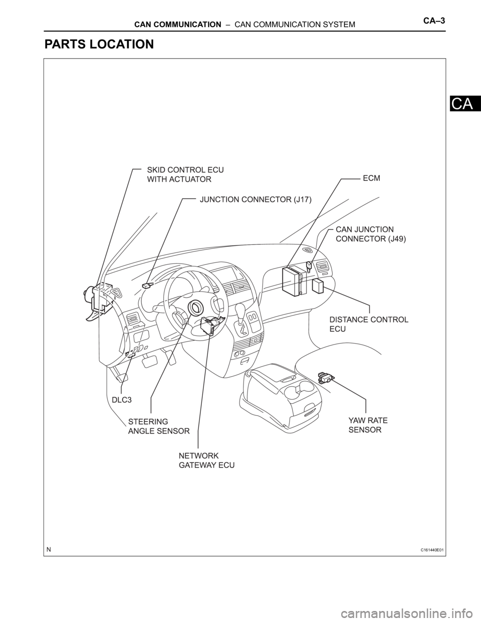
PARTS LOCATION
C161440E01
Page 858 of 3000
CA–4CAN COMMUNICATION – CAN COMMUNICATION SYSTEM
CA
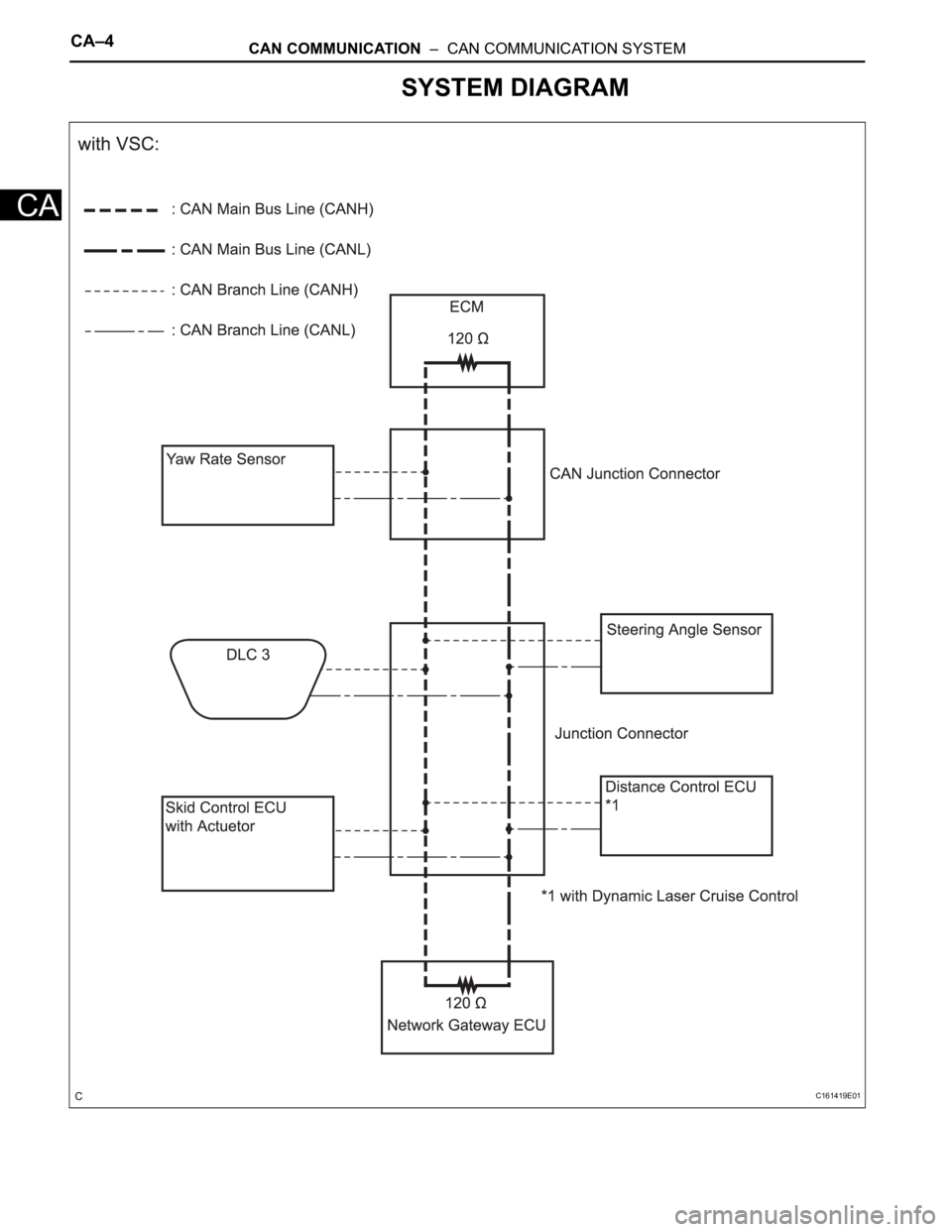
SYSTEM DIAGRAM
C161419E01
Page 859 of 3000
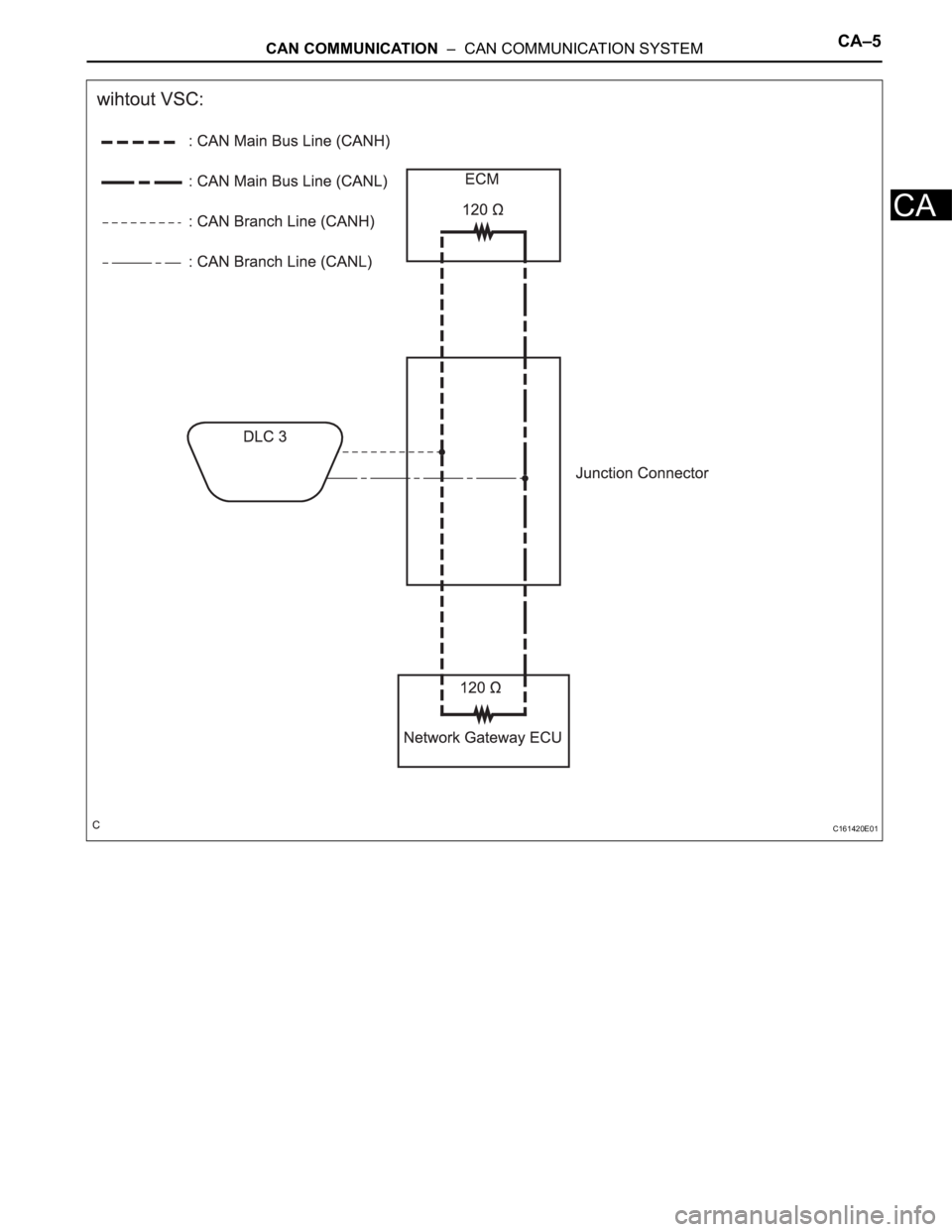
CAN COMMUNICATION – CAN COMMUNICATION SYSTEMCA–5
CA
C161420E01
Page 860 of 3000
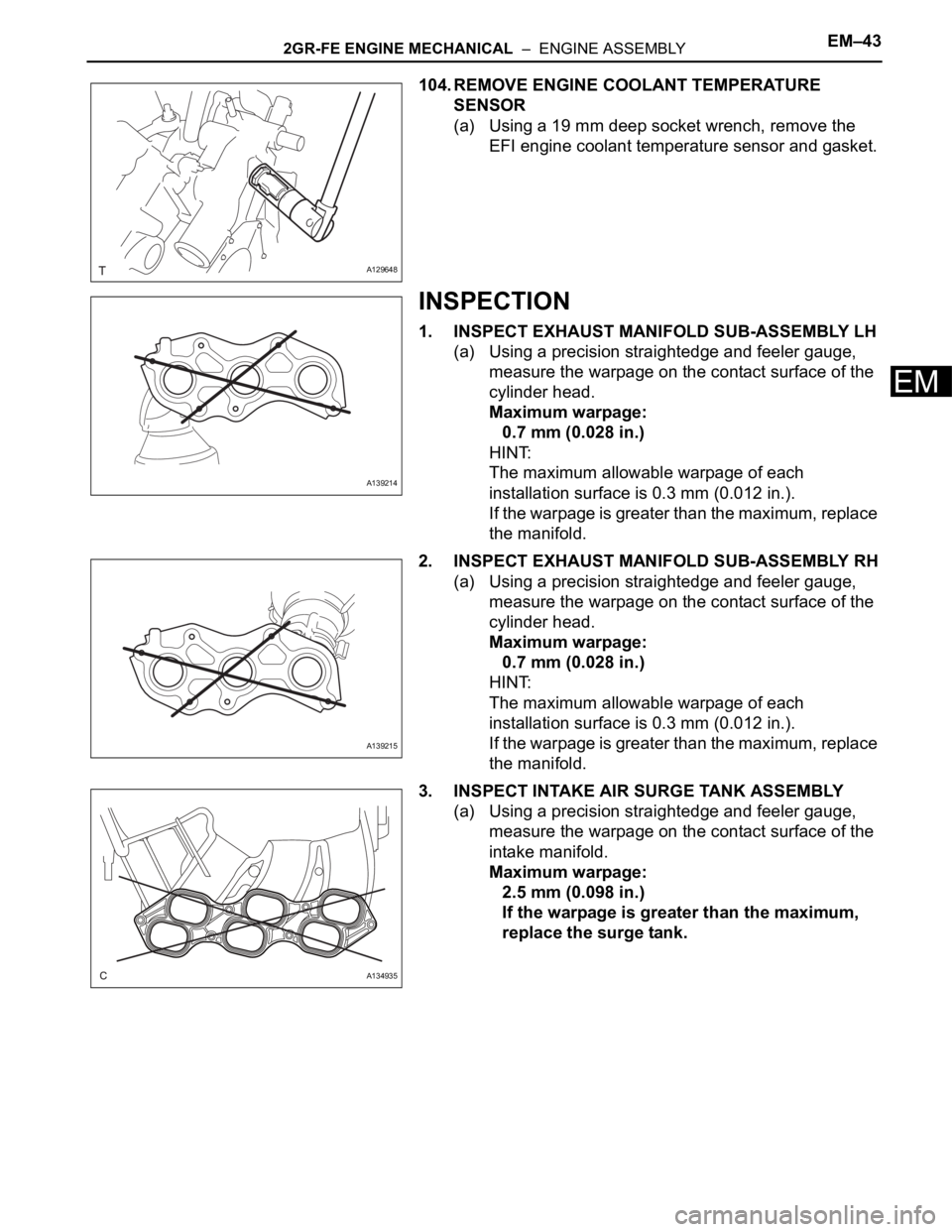
2GR-FE ENGINE MECHANICAL – ENGINE ASSEMBLYEM–43
EM
104. REMOVE ENGINE COOLANT TEMPERATURE
SENSOR
(a) Using a 19 mm deep socket wrench, remove the
EFI engine coolant temperature sensor and gasket.
INSPECTION
1. INSPECT EXHAUST MANIFOLD SUB-ASSEMBLY LH
(a) Using a precision straightedge and feeler gauge,
measure the warpage on the contact surface of the
cylinder head.
Maximum warpage:
0.7 mm (0.028 in.)
HINT:
The maximum allowable warpage of each
installation surface is 0.3 mm (0.012 in.).
If the warpage is greater than the maximum, replace
the manifold.
2. INSPECT EXHAUST MANIFOLD SUB-ASSEMBLY RH
(a) Using a precision straightedge and feeler gauge,
measure the warpage on the contact surface of the
cylinder head.
Maximum warpage:
0.7 mm (0.028 in.)
HINT:
The maximum allowable warpage of each
installation surface is 0.3 mm (0.012 in.).
If the warpage is greater than the maximum, replace
the manifold.
3. INSPECT INTAKE AIR SURGE TANK ASSEMBLY
(a) Using a precision straightedge and feeler gauge,
measure the warpage on the contact surface of the
intake manifold.
Maximum warpage:
2.5 mm (0.098 in.)
If the warpage is greater than the maximum,
replace the surge tank.
A129648
A139214
A139215
A134935