radiator TOYOTA SIENNA 2007 Service Repair Manual
[x] Cancel search | Manufacturer: TOYOTA, Model Year: 2007, Model line: SIENNA, Model: TOYOTA SIENNA 2007Pages: 3000, PDF Size: 52.26 MB
Page 7 of 3000

PP–6PREPARATION – 2GR-FE ENGINE MECHANICAL
PP
EQUIPMENT
Abrasive compound
Brush
Caliper gauge
Carbide cutter (30
)
Carbide cutter (45
)
Carbide cutter (60
)
Carbide cutter (75
)
Connecting rod aligner
Cylinder gauge
Dial indicator
Dye penetrant
Engine tune-up tester
Groove cleaning tool
Heater
Micrometer
Piston ring compressor
Piston ring expander
Plastigage
Precision straight edge
Press
Reamer (5.5 mm)
Ridge reamer
Soft brush
Solvent
Spring tester
Steel square
Thermometer
To r q u e w r e n c h
Torx socket wrench
Valve seat cutter
Valve guide bushing brush
V-block
Vernier calipers
Wire brush
Bar
Chain Block
CO/HC meter
Compression gauge
Dial indicator with magnetic base
Engine Sling Device
Feeler gauge
Radiator cap tester
Slide calipers
Tachometer
Timing light
Wooden block
Deep socket wrench
Screwdriver
Hammer
Page 29 of 3000
EM–302GR-FE ENGINE MECHANICAL – ENGINE ASSEMBLY
EM
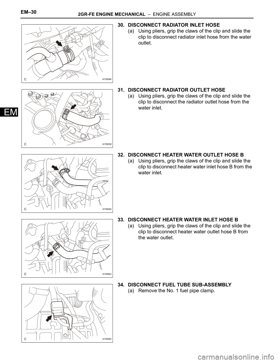
30. DISCONNECT RADIATOR INLET HOSE
(a) Using pliers, grip the claws of the clip and slide the
clip to disconnect radiator inlet hose from the water
outlet.
31. DISCONNECT RADIATOR OUTLET HOSE
(a) Using pliers, grip the claws of the clip and slide the
clip to disconnect the radiator outlet hose from the
water inlet.
32. DISCONNECT HEATER WATER OUTLET HOSE B
(a) Using pliers, grip the claws of the clip and slide the
clip to disconnect heater water inlet hose B from the
water inlet.
33. DISCONNECT HEATER WATER INLET HOSE B
(a) Using pliers, grip the claws of the clip and slide the
clip to disconnect heater water outlet hose B from
the water outlet.
34. DISCONNECT FUEL TUBE SUB-ASSEMBLY
(a) Remove the No. 1 fuel pipe clamp.
A155046
A155038
A155044
A155043
A155045
Page 54 of 3000
IN–42INTRODUCTION – HOW TO TROUBLESHOOT ECU CONTROLLED SYSTEMS
IN
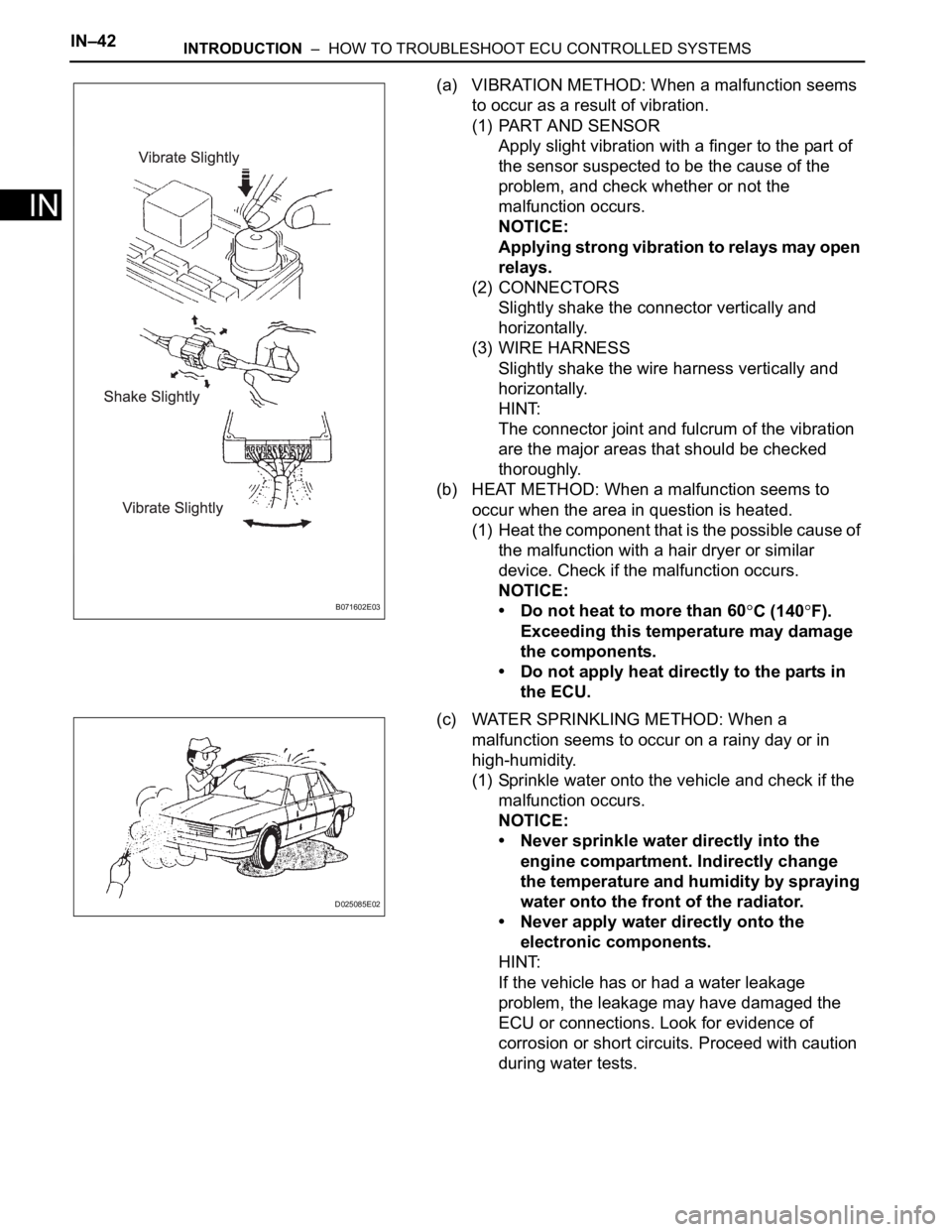
(a) VIBRATION METHOD: When a malfunction seems
to occur as a result of vibration.
(1) PART AND SENSOR
Apply slight vibration with a finger to the part of
the sensor suspected to be the cause of the
problem, and check whether or not the
malfunction occurs.
NOTICE:
Applying strong vibration to relays may open
relays.
(2) CONNECTORS
Slightly shake the connector vertically and
horizontally.
(3) WIRE HARNESS
Slightly shake the wire harness vertically and
horizontally.
HINT:
The connector joint and fulcrum of the vibration
are the major areas that should be checked
thoroughly.
(b) HEAT METHOD: When a malfunction seems to
occur when the area in question is heated.
(1) Heat the component that is the possible cause of
the malfunction with a hair dryer or similar
device. Check if the malfunction occurs.
NOTICE:
• Do not heat to more than 60
C (140F).
Exceeding this temperature may damage
the components.
• Do not apply heat directly to the parts in
the ECU.
(c) WATER SPRINKLING METHOD: When a
malfunction seems to occur on a rainy day or in
high-humidity.
(1) Sprinkle water onto the vehicle and check if the
malfunction occurs.
NOTICE:
• Never sprinkle water directly into the
engine compartment. Indirectly change
the temperature and humidity by spraying
water onto the front of the radiator.
• Never apply water directly onto the
electronic components.
HINT:
If the vehicle has or had a water leakage
problem, the leakage may have damaged the
ECU or connections. Look for evidence of
corrosion or short circuits. Proceed with caution
during water tests.B071602E03
D025085E02
Page 72 of 3000
IN–42INTRODUCTION – HOW TO TROUBLESHOOT ECU CONTROLLED SYSTEMS
IN
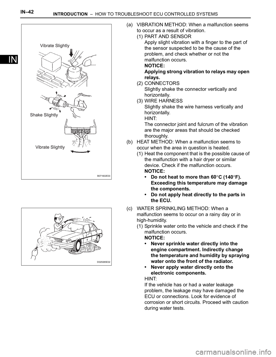
(a) VIBRATION METHOD: When a malfunction seems
to occur as a result of vibration.
(1) PART AND SENSOR
Apply slight vibration with a finger to the part of
the sensor suspected to be the cause of the
problem, and check whether or not the
malfunction occurs.
NOTICE:
Applying strong vibration to relays may open
relays.
(2) CONNECTORS
Slightly shake the connector vertically and
horizontally.
(3) WIRE HARNESS
Slightly shake the wire harness vertically and
horizontally.
HINT:
The connector joint and fulcrum of the vibration
are the major areas that should be checked
thoroughly.
(b) HEAT METHOD: When a malfunction seems to
occur when the area in question is heated.
(1) Heat the component that is the possible cause of
the malfunction with a hair dryer or similar
device. Check if the malfunction occurs.
NOTICE:
• Do not heat to more than 60
C (140F).
Exceeding this temperature may damage
the components.
• Do not apply heat directly to the parts in
the ECU.
(c) WATER SPRINKLING METHOD: When a
malfunction seems to occur on a rainy day or in
high-humidity.
(1) Sprinkle water onto the vehicle and check if the
malfunction occurs.
NOTICE:
• Never sprinkle water directly into the
engine compartment. Indirectly change
the temperature and humidity by spraying
water onto the front of the radiator.
• Never apply water directly onto the
electronic components.
HINT:
If the vehicle has or had a water leakage
problem, the leakage may have damaged the
ECU or connections. Look for evidence of
corrosion or short circuits. Proceed with caution
during water tests.B071602E03
D025085E02
Page 76 of 3000

2GR-FE COOLING – COOLING FAN SYSTEMCO–5
CO
ON-VEHICLE INSPECTION
1. INSPECT COOLING FAN SYSTEM
(a) Put the vehicle in the following conditions:
(1) The engine switch is off.
(2) The coolant temperature is less than 95
C
(203
F).
(3) The battery voltage is between 9 and 14 V.
(4) The A/C switch is OFF.
(b) Clamp the 400 A probe of an ammeter over the M+
wire of each cooling fan motor.
(c) Turn the ignition switch to the ON position and wait
for approximately 10 seconds. Check that the fan
stops.
(d) Start the engine. Check that the fan stops with the
engine idling.
HINT:
• Make sure that the radiator engine coolant
temperature is less than 95
C (203F).
• Turn the A/C switch OFF.
(e) Check that the fan operates when the A/C switch is
turned ON (MAX COOL and the magnetic clutch is
operating).
Standard current
HINT:
The coolant temperature is less than 95
C (203F).
(f) Check that the fan operates when the engine
coolant temperature sensor connector is
disconnected.
Standard current
Item Specified Condition
No. 1 cooling fan motor 5 to 14 A
No. 2 cooling fan motor 4 to 12 A
Item Specified Condition
No. 1 cooling fan motor 5 to 19 A
No. 2 cooling fan motor 4 to 16 A
Page 127 of 3000

PP–14PREPARATION – 2GR-FE COOLING
PP
EQUIPMENT
Ohmmeter -
Radiator cap tester -
Thermometer -
To r q u e w r e n c h -
Slide calipers -
Heater -
Ammeter (A) -
Page 155 of 3000

PP–64PREPARATION – AIR CONDITIONING
PP
EQUIPMENT
Vo l t m e t e r
Anmeter
Ohmmeter
Vinyl tape
Hexagon wrench 4 mm (0.15 in.)
Hexagon wrench 14 mm (0.55 in.)
Gas leak detector
Dial indicator with magnetic base
Radiator cap tester
To r q u e w r e n c h
Gas leak detector
Page 204 of 3000
AIR CONDITIONING – COMPRESSOR AND MAGNETIC CLUTCHAC–227
AC
REMOVAL
1. RECOVER REFRIGERANT FROM REFRIGERATION
SYSTEM (See page AC-172)
2. REMOVE FRONT WHEEL RH
3. REMOVE FRONT FENDER APRON SEAL RH (See
page EM-26)
4. REMOVE V-RIBBED BELT (See page EM-6)
5. REMOVE RADIATOR AND FAN ASSEMBLY
(See page CO-28)
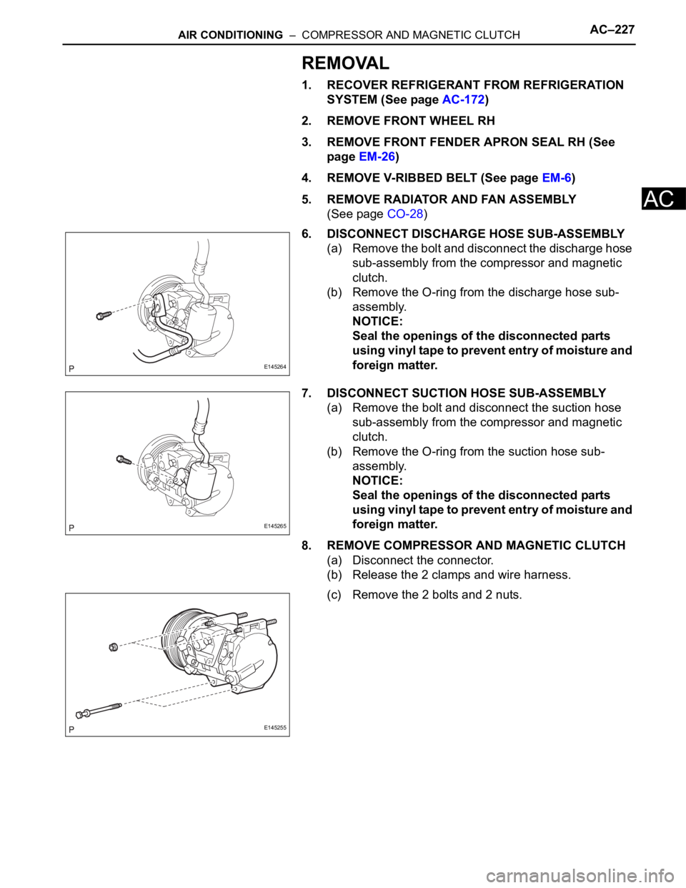
6. DISCONNECT DISCHARGE HOSE SUB-ASSEMBLY
(a) Remove the bolt and disconnect the discharge hose
sub-assembly from the compressor and magnetic
clutch.
(b) Remove the O-ring from the discharge hose sub-
assembly.
NOTICE:
Seal the openings of the disconnected parts
using vinyl tape to prevent entry of moisture and
foreign matter.
7. DISCONNECT SUCTION HOSE SUB-ASSEMBLY
(a) Remove the bolt and disconnect the suction hose
sub-assembly from the compressor and magnetic
clutch.
(b) Remove the O-ring from the suction hose sub-
assembly.
NOTICE:
Seal the openings of the disconnected parts
using vinyl tape to prevent entry of moisture and
foreign matter.
8. REMOVE COMPRESSOR AND MAGNETIC CLUTCH
(a) Disconnect the connector.
(b) Release the 2 clamps and wire harness.
(c) Remove the 2 bolts and 2 nuts.
E145264
E145265
E145255
Page 207 of 3000
AIR CONDITIONING – CONDENSERAC–237
AC
REMOVAL
1. RECOVER REFRIGERANT FROM REFRIGERATION
SYSTEM (See page AC-172)
2. REMOVE NO. 2 AIR CLEANER INLET (See page EM-
28)
3. REMOVE FRONT BUMPER ASSEMBLY (See page
ET-3)
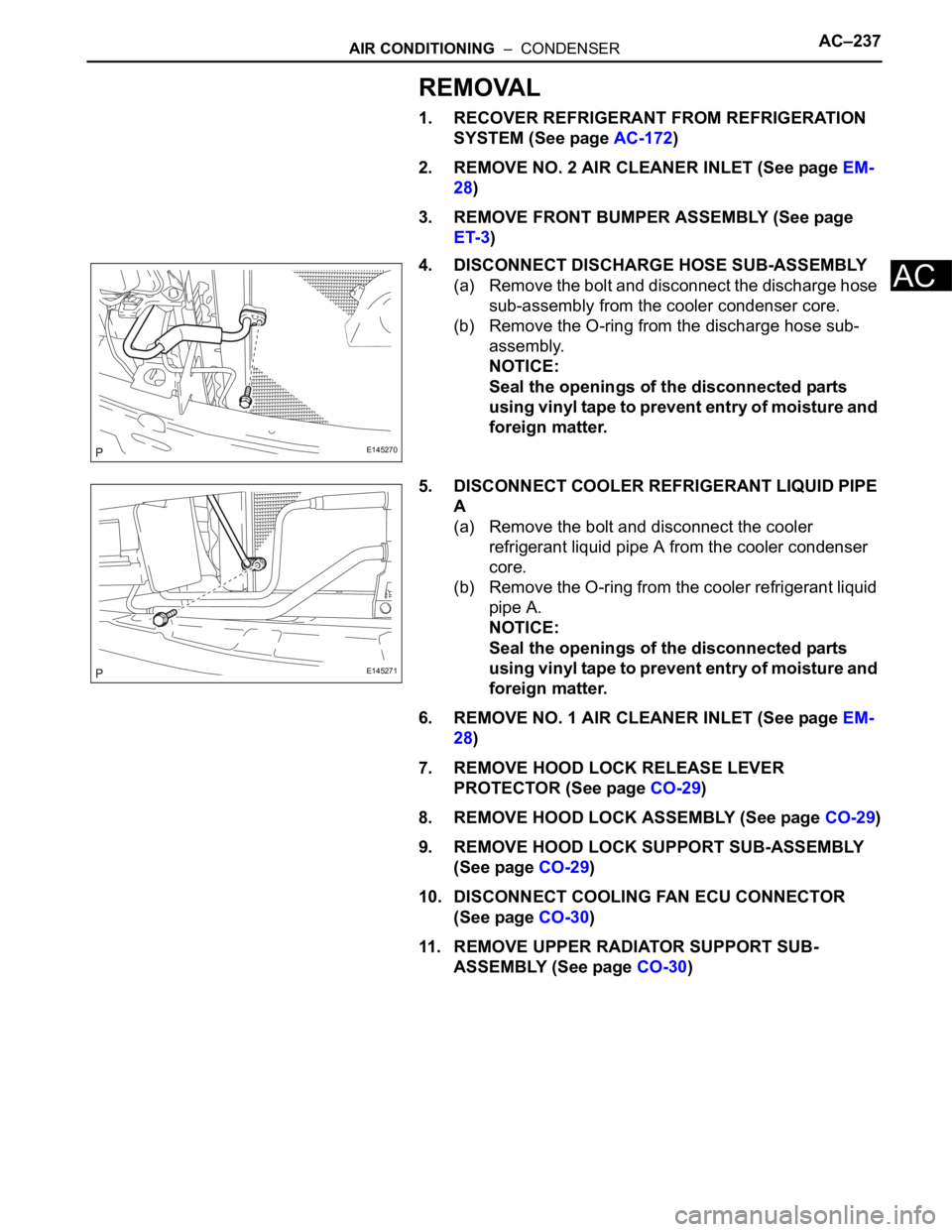
4. DISCONNECT DISCHARGE HOSE SUB-ASSEMBLY
(a) Remove the bolt and disconnect the discharge hose
sub-assembly from the cooler condenser core.
(b) Remove the O-ring from the discharge hose sub-
assembly.
NOTICE:
Seal the openings of the disconnected parts
using vinyl tape to prevent entry of moisture and
foreign matter.
5. DISCONNECT COOLER REFRIGERANT LIQUID PIPE
A
(a) Remove the bolt and disconnect the cooler
refrigerant liquid pipe A from the cooler condenser
core.
(b) Remove the O-ring from the cooler refrigerant liquid
pipe A.
NOTICE:
Seal the openings of the disconnected parts
using vinyl tape to prevent entry of moisture and
foreign matter.
6. REMOVE NO. 1 AIR CLEANER INLET (See page EM-
28)
7. REMOVE HOOD LOCK RELEASE LEVER
PROTECTOR (See page CO-29)
8. REMOVE HOOD LOCK ASSEMBLY (See page CO-29)
9. REMOVE HOOD LOCK SUPPORT SUB-ASSEMBLY
(See page CO-29)
10. DISCONNECT COOLING FAN ECU CONNECTOR
(See page CO-30)
11. REMOVE UPPER RADIATOR SUPPORT SUB-
ASSEMBLY (See page CO-30)
E145270
E145271
Page 208 of 3000
AC–238AIR CONDITIONING – CONDENSER
AC
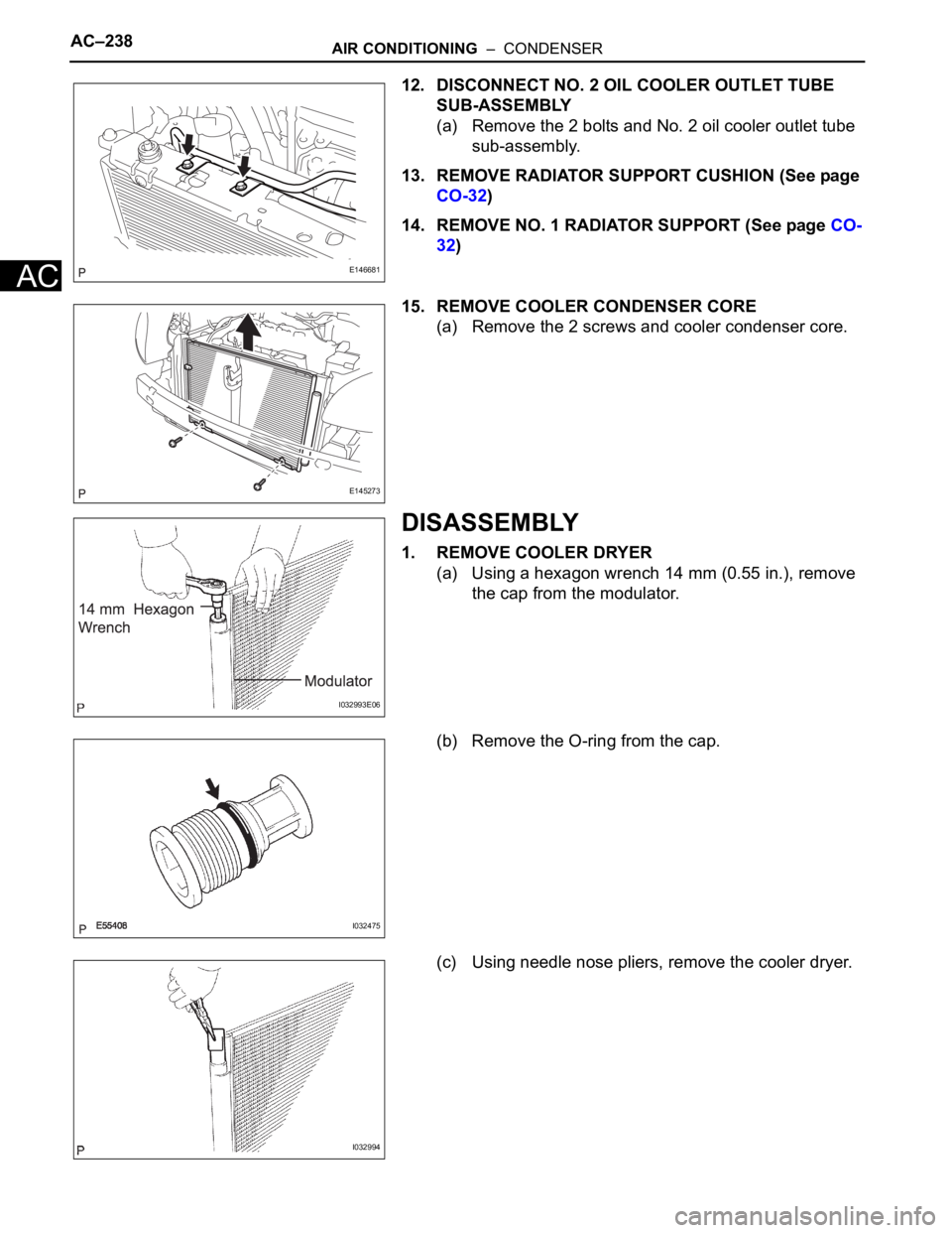
12. DISCONNECT NO. 2 OIL COOLER OUTLET TUBE
SUB-ASSEMBLY
(a) Remove the 2 bolts and No. 2 oil cooler outlet tube
sub-assembly.
13. REMOVE RADIATOR SUPPORT CUSHION (See page
CO-32)
14. REMOVE NO. 1 RADIATOR SUPPORT (See page CO-
32)
15. REMOVE COOLER CONDENSER CORE
(a) Remove the 2 screws and cooler condenser core.
DISASSEMBLY
1. REMOVE COOLER DRYER
(a) Using a hexagon wrench 14 mm (0.55 in.), remove
the cap from the modulator.
(b) Remove the O-ring from the cap.
(c) Using needle nose pliers, remove the cooler dryer.
E146681
E145273
I032993E06
I032475
I032994