coolant TOYOTA SIENNA 2007 Service Repair Manual
[x] Cancel search | Manufacturer: TOYOTA, Model Year: 2007, Model line: SIENNA, Model: TOYOTA SIENNA 2007Pages: 3000, PDF Size: 52.26 MB
Page 21 of 3000

2GR-FE ENGINE CONTROL SYSTEM – KNOCK SENSORES–521
ES
REMOVAL
1. DISCHARGE FUEL SYSTEM PRESSURE
(See page FU-13)
2. REMOVE V-BANK COVER SUB-ASSEMBLY (See
page EM-28)
3. DRAIN ENGINE COOLANT (See page CO-6)
4. REMOVE WINDSHIELD WIPER MOTOR ASSEMBLY
HINT:
(See page WW-4)
5. REMOVE FRONT OUTER COWL TOP PANEL SUB-
ASSEMBLY (See page EM-27)
6. REMOVE AIR CLEANER CAP SUB-ASSEMBLY (See
page ES-493)
7. REMOVE AIR CLEANER CASE SUB-ASSEMBLY (See
page EM-28)
8. REMOVE INTAKE AIR SURGE TANK ASSEMBLY
(a) Disconnect the 2 water by-pass hoses from the
throttle body [A].
(b) Disconnect the vapor feed hose [B].
(c) Disconnect the throttle body connector and clamp
[C].
(d) Disconnect the ventilation hose [D].
(e) Disconnect the union to check valve hose [E].
(f) Disconnect the connector [F].
A129464E07
A138457E04
A129467
Page 23 of 3000
![TOYOTA SIENNA 2007 Service Repair Manual 2GR-FE ENGINE CONTROL SYSTEM – KNOCK SENSORES–523
ES
(a) Install a new gasket to the intake air surge tank [A].
(b) Using a 5 mm hexagon socket wrench, install the 4
bolts [B].
Torque: 18 N*m ( TOYOTA SIENNA 2007 Service Repair Manual 2GR-FE ENGINE CONTROL SYSTEM – KNOCK SENSORES–523
ES
(a) Install a new gasket to the intake air surge tank [A].
(b) Using a 5 mm hexagon socket wrench, install the 4
bolts [B].
Torque: 18 N*m (](/img/14/57466/w960_57466-22.png)
2GR-FE ENGINE CONTROL SYSTEM – KNOCK SENSORES–523
ES
(a) Install a new gasket to the intake air surge tank [A].
(b) Using a 5 mm hexagon socket wrench, install the 4
bolts [B].
Torque: 18 N*m (184 kgf*cm, 13 ft.*lbf)
(c) Install the intake air surge tank with the 2 nuts and 2
bolts [C].
Torque: Nut
16 N*m (163 kgf*cm, 12 ft.*lbf)
Bolt
21 N*m (214 kgf*cm, 15 ft.*lbf)
(d) Connect the connector [D].
(e) Connect the union to check valve hose [E].
(f) Connect the ventilation hose No. 2 [F].
(g) Install the clamp and connect the throttle with motor
body assembly connector [G].
(h) Connect the vapor feed hose [H].
(i) Connect the 2 water by-pass hoses to the throttle
with motor body assembly [I].
5. INSTALL AIR CLEANER CASE SUB-ASSEMBLY (See
page EM-59)
6. INSTALL AIR CLEANER CAP SUB-ASSEMBLY (See
page ES-496)
7. ADD ENGINE COOLANT (See page CO-7)
8. INSPECT FOR ENGINE COOLANT LEAK (See page
CO-1)
9. INSPECT FOR FUEL LEAK (See page FU-7)
10. INSTALL FRONT OUTER COWL TOP PANEL SUB-
ASSEMBLY (See page EM-61)
11. INSTALL WINDSHIELD WIPER MOTOR ASSEMBLY
HINT:
(See page WW-5)
A129468E09
A129467
A138457E05
A129464E08
Page 25 of 3000

EM–262GR-FE ENGINE MECHANICAL – ENGINE ASSEMBLY
EM
REMOVAL
1. DISCHARGE FUEL SYSTEM PRESSURE (See page
FU-13)
2. DISCHARGE REFRIGERANT FROM
REFRIGERATION SYSTEM (See page AC-172)
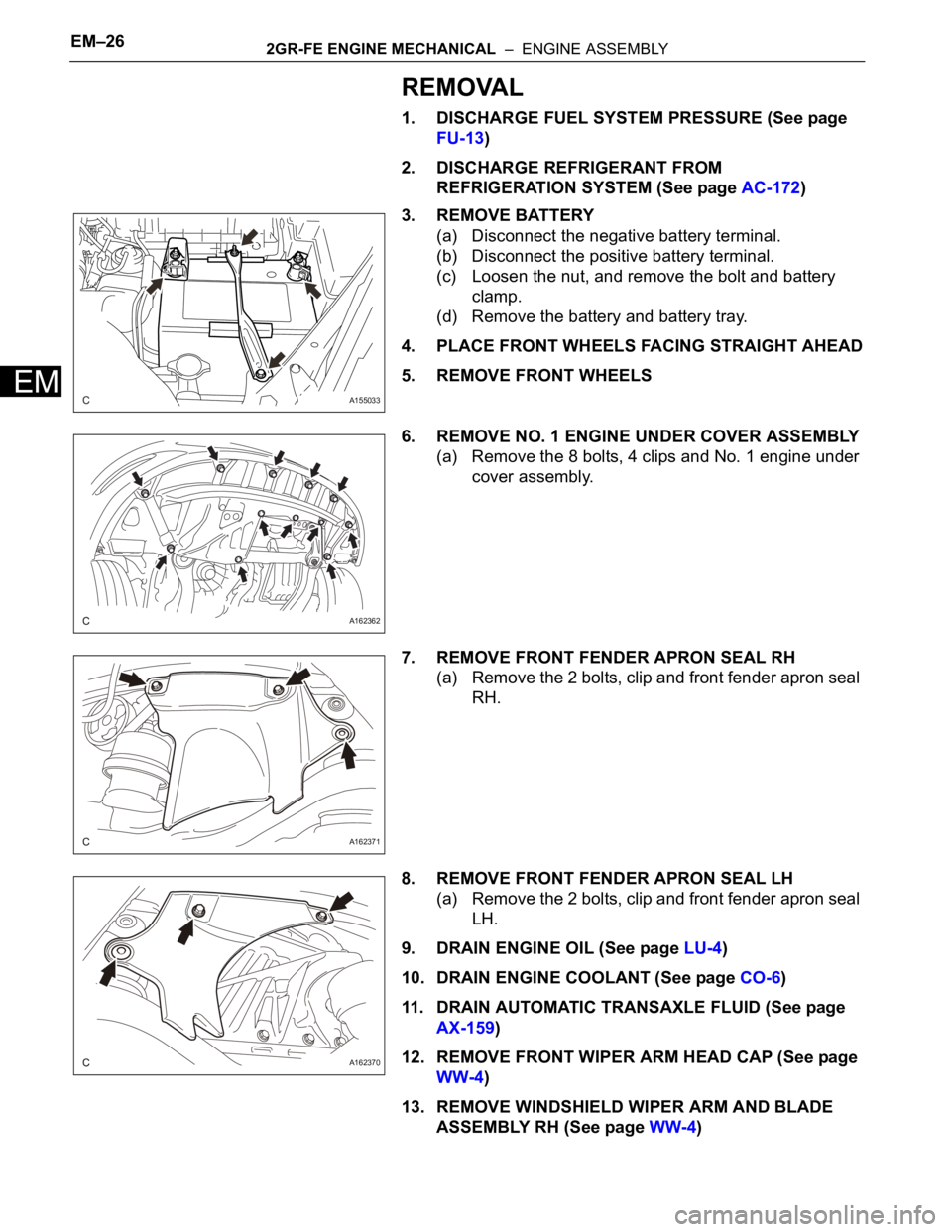
3. REMOVE BATTERY
(a) Disconnect the negative battery terminal.
(b) Disconnect the positive battery terminal.
(c) Loosen the nut, and remove the bolt and battery
clamp.
(d) Remove the battery and battery tray.
4. PLACE FRONT WHEELS FACING STRAIGHT AHEAD
5. REMOVE FRONT WHEELS
6. REMOVE NO. 1 ENGINE UNDER COVER ASSEMBLY
(a) Remove the 8 bolts, 4 clips and No. 1 engine under
cover assembly.
7. REMOVE FRONT FENDER APRON SEAL RH
(a) Remove the 2 bolts, clip and front fender apron seal
RH.
8. REMOVE FRONT FENDER APRON SEAL LH
(a) Remove the 2 bolts, clip and front fender apron seal
LH.
9. DRAIN ENGINE OIL (See page LU-4)
10. DRAIN ENGINE COOLANT (See page CO-6)
11. DRAIN AUTOMATIC TRANSAXLE FLUID (See page
AX-159)
12. REMOVE FRONT WIPER ARM HEAD CAP (See page
WW-4)
13. REMOVE WINDSHIELD WIPER ARM AND BLADE
ASSEMBLY RH (See page WW-4)
A155033
A162362
A162371
A162370
Page 57 of 3000

IN–50INTRODUCTION – TERMS
IN
GLOSSARY OF SAE AND TOYOTA
TERMS
This glossary lists all SAE-J1930 terms and abbreviations
used in this manual in compliance with SAE
recommendations, as well as their TOYOTA equivalents.
SAE
ABBREVIATIONSSAE TERMSTOYOTA TERMS
( )-ABBREVIATIONS
A/C Air Conditioning Air Conditioner
ACL Air Cleaner Air Cleaner, A/CL
AIR Secondary Air Injection Air Injection (AI)
AP Accelerator Pedal -
B+ Battery Positive Voltage +B, Battery Voltage
BARO Barometric Pressure HAC
CAC Charge Air Cooler Intercooler
CARB Carburetor Carburetor
CFI Continuous Fuel Injection -
CKP Crankshaft Position Crank Angle
CL Closed Loop Closed Loop
CMP Camshaft Position Cam Angle
CPP Clutch Pedal Position -
CTOX Continuous Trap Oxidizer -
CTP Closed Throttle Position LL ON, Idle ON
DFI Direct Fuel Injection Direct Injection (DI./INJ)
DI Distributor Ignition -
DLC3 Data Link Connector 3 OBD II Diagnostic Connector
DTC Diagnostic Trouble Code Diagnostic Trouble Code
DTM Diagnostic Test Mode -
ECL Engine Coolant Level -
ECM Engine Control Module Engine Electronic Control Unit (ECU)
ECT Engine Coolant Temperature Coolant Temperature, Water Temperature (THW)
EEPROM Electrically Erasable Programmable Read Only MemoryElectrically Erasable Programmable Read Only
Memory (EEPROM), Erasable Programmable Read
Only Memory (EPROM)
EFE Early Fuel Evaporation Cold Mixture Heater (CMH), Heat Control Valve (HCV)
EGR Exhaust Gas Recirculation Exhaust Gas Recirculation (EGR)
EI Electronic Ignition Distributorless Ignition (DLI)
EM Engine Modification Engine Modification (EM)
EPROM Erasable Programmable Read Only Memory Programmable Read Only Memory (PROM)
EVAP Evaporative Emission Evaporative Emission Control (EVAP)
FC Fan Control -
FEEPROMFlash Electrically Erasable Programmable Read Only
Memory-
FEPROM Flash Erasable Programmable Read Only Memory -
FF Flexible Fuel -
FP Fuel Pump Fuel Pump
GEN Generator Alternator
GND Ground Ground (GND)
HO2S Heated Oxygen SensorHeated Oxygen Sensor (HO
2S)
IAC Idle Air Control Idle Speed Control (ISC)
IAT Intake Air Temperature Intake or Inlet Air Temperature
ICM Ignition Control Module -
Page 76 of 3000

2GR-FE COOLING – COOLING FAN SYSTEMCO–5
CO
ON-VEHICLE INSPECTION
1. INSPECT COOLING FAN SYSTEM
(a) Put the vehicle in the following conditions:
(1) The engine switch is off.
(2) The coolant temperature is less than 95
C
(203
F).
(3) The battery voltage is between 9 and 14 V.
(4) The A/C switch is OFF.
(b) Clamp the 400 A probe of an ammeter over the M+
wire of each cooling fan motor.
(c) Turn the ignition switch to the ON position and wait
for approximately 10 seconds. Check that the fan
stops.
(d) Start the engine. Check that the fan stops with the
engine idling.
HINT:
• Make sure that the radiator engine coolant
temperature is less than 95
C (203F).
• Turn the A/C switch OFF.
(e) Check that the fan operates when the A/C switch is
turned ON (MAX COOL and the magnetic clutch is
operating).
Standard current
HINT:
The coolant temperature is less than 95
C (203F).
(f) Check that the fan operates when the engine
coolant temperature sensor connector is
disconnected.
Standard current
Item Specified Condition
No. 1 cooling fan motor 5 to 14 A
No. 2 cooling fan motor 4 to 12 A
Item Specified Condition
No. 1 cooling fan motor 5 to 19 A
No. 2 cooling fan motor 4 to 16 A
Page 77 of 3000

CO–62GR-FE COOLING – COOLING FAN SYSTEM
CO
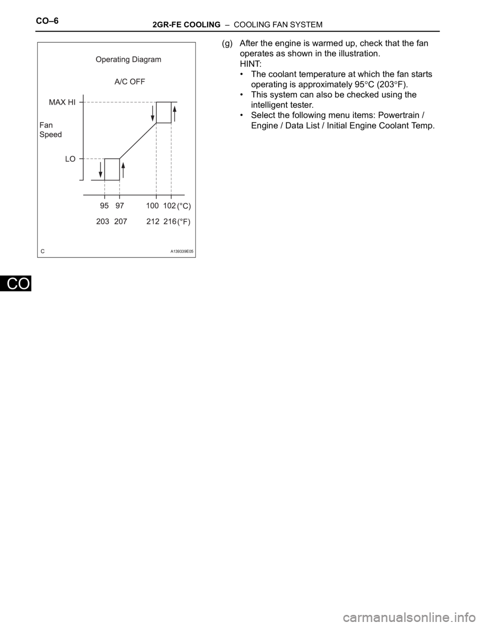
(g) After the engine is warmed up, check that the fan
operates as shown in the illustration.
HINT:
• The coolant temperature at which the fan starts
operating is approximately 95
C (203F).
• This system can also be checked using the
intelligent tester.
• Select the following menu items: Powertrain /
Engine / Data List / Initial Engine Coolant Temp.
A139339E05
Page 128 of 3000

PREPARATION – 2GR-FE COOLINGPP–15
PP
COOLANT
Capacity Classification
11.3 liters (12.0 US qts, 10.0 Imp. qts) Use only "TOYOTA Super Long Life Coolant" or similar high quality
ethylene glycol based non-silicate, non-amine, non-nitrite, non-borate
coolant with long-life hybrid organic acid technology (coolant with
long-life hybrid organic acid technology consists of a combination of
low phosphates and organic acids).
Page 197 of 3000

SS–10SERVICE SPECIFICATIONS – 2GR-FE ENGINE MECHANICAL
SS
TORQUE SPECIFICATIONS
Part Tightened N*m kgf*cm ft.*lbf
Ignition coil assembly x Cylinder head cover sub-assembly 10 102 7
No. 1 engine hanger x Cylinder head sub-assembly RH 33 337 24
No. 2 engine hanger x Cylinder head sub-assembly LH 33 337 24
Engine mounting bracket RH x Cylinder block sub-assembly 54 551 40
No. 1 oil level gauge guide x Cylinder head sub-assembly 21 214 15
No. 2 oil level gauge guide x Cylinder block sub-assembly 21 214 15
No. 2 idler pulley sub-assembly x Timing chain cover sub-assembly 43 438 32
V-ribbed belt tensioner assembly x Cylinder block sub-assembly 43 438 32
Intake manifold x Cylinder head sub-assembly 21 214 15
Exhaust manifold sub-assembly RH x Cylinder head sub-assembly
RH21 214 15
Exhaust manifold sub-assembly LH x Cylinder head sub-assembly LH 21 214 15
Drive plate & ring gear sub-assembly x Crankshaft 83 850 61
Air cleaner case sub-assembly x Body 5.0 51 44 in.*lbf
Air cleaner case sub-assembly x Air cleaner bracket 5.0 51 44 in.*lbf
Engine coolant temperature x water by-pass joint RR 20 200 14
Engine assembly with Transaxle x Body A 85 867 63
B 32 329 24
No. 2 manifold stay x Exhaust manifold sub-assembly LH 34 347 25
No. 2 manifold stay x Cylinder block sub-assembly 34 347 25
No. 1 air cleaner inlet x Body 5.0 51 44 in.*lbf
No. 2 air cleaner inlet x Body 5.0 51 44 in.*lbf
Battery clamp x Body Bolt 5.5 56 49 in.*lbf
Nut 5.5 56 49 in.*lbf
Throttle body bracket x Intake air surge tank assembly 21 214 15
Throttle body bracket x Cylinder head cover sub-assembly RH 21 21415
No. 1 surge tank stay x Intake air surge tank assembly 21 214 15
No. 1 surge tank stay x Cylinder head cover sub-assembly RH 21 21415
No. 1 cowl top to cowl brace inner x Body 7.5 76 66 in.*lbf
No. 1 cowl top to cowl brace inner x Front outer cowl top panel sub-
assembly7.5 76 66 in.*lbf
Front outer cowl top panel sub-assembly x Body 7.5 76 66 in.*lbf
Fuel pump resistor x Front outer cowl top panel sub-assembly 7.576 66 in.*lbf
Radio setting condenser x Cylinder head cover sub-assembly RH 10102 7
Radio setting condense x Cylinder head cover sub-assembly LH 10 102 7
Intake air resonator sub-assembly x Body 5.0 51 44 in.*lbf
Air cleaner bracket x Body 7.8 80 69 in.*lbf
No. 1 vacuum switching valve assembly x Cylinder head cover sub-
assembly10 102 7
Engine mounting bracket RR x Cylinder block sub-assembly 64 650 47
Steering intermediate shaft x Steering gear 35 360 26
Stabilizer link x Shock absorber 74 755 55
Tie rod assembly x Steering gear 49 500 36
Front speed sensor x Front axle 8.0 85 71 in.*lbf
Front axle hub nut x Front drive shaft 294 2998 217
Cooler compressor assembly x V-ribbed belt tensioner 25 250 18
Cooler compressor assembly x Discharge hose sub-assembly 5.4 55 48 in.*lbf
Cooler compressor assembly x Suction hose sub-assembly 5.4 55 48 in.*lbf
Page 318 of 3000

2GR-FE ENGINE CONTROL SYSTEM – SFI SYSTEMES–1
ES
SFI SYSTEM
PRECAUTION
1. INITIALIZATION
NOTICE:
• Perform RESET MEMORY (AT initialization) when
replacing the automatic transaxle assembly, engine
assembly or ECM (See page AX-16).
• Perform REGISTRATION (VIN registration) when
replacing the ECM (See page ES-15).
HINT:
Initialization cannot be completed by only removing the
battery.
2. FOR USING INTELLIGENT TESTER
CAUTION:
Observe the following items for safety reasons:
• Before using the tester, read the instruction
manual.
• Prevent the tester cable from being caught on the
pedals, shift lever and steering wheel when
driving with the tester connected to the vehicle.
• When driving the vehicle for testing purposes
using the tester, two persons are required. One is
for driving the vehicle, and the other operates the
tester.
3. FOR USING BATTERY DURING INSPECTION
(a) While using the battery during inspection, do not
bring the positive and negative tester probes too
close to each other as a short circuit may occur.
4. COOLING FAN SYSTEM
NOTICE:
• When the ignition switch is turned off and the engine
temperature is high, the cooling fans may operate for
approximately 3 minutes.
• After turning the ignition switch off, keep hands and
objects away from the fans when they are operating.
HINT:
If all of the following are met for a certain period of time during
a few minute period immediately before the engine is
stopped, the electric fans will continue to operate for 3
minutes after the engine is stopped. This is performed to
ensure restartability and stabilize idle speed.
– The intelligent tester indicates a very high coolant
temperature.
– The intelligent tester indicates a high outside air
temperature.
– The vehicle has been driven under high load (driving on an
uphill or equivalent).
The following sensors are used for this control:
– Coolant temperature sensor
– Outside air temperature sensor
–MAF sensor
– Vehicle speed sensors
Page 326 of 3000

ES–2582GR-FE ENGINE CONTROL SYSTEM – SFI SYSTEM
ES
MONITOR DESCRIPTION
The ECM uses the sensors mounted in front of and behind the three-way catalyst (TWC) to monitor its
efficiency. The first sensor, an Air Fuel ratio (A/F) sensor, sends pre-catalyst A/F ratio information to the
ECM. The second sensor, a heated oxygen sensor (O2S), sends post-catalyst information to the ECM.
The ECM compares these 2 signals to judge the efficiency of the catalyst and the catalyst's ability to store
oxygen. During normal operation, the TWC stores and releases oxygen as needed. The capacity to store
oxygen results in a low variation in the post-TWC exhaust stream.
If the catalyst is functioning normally, the waveform of the heated oxygen sensor slowly switches between
RICH and LEAN. If the catalyst is deteriorated, the waveform will alternate frequently between RICH and
LEAN. As the catalyst efficiency degrades, its ability to store oxygen is reduced and the catalyst output
becomes more variable. When running the monitor, the ECM compares sensor 1 signals (A/F sensor)
over a specific amount of time to determine catalyst efficiency. The ECM begins by calculating the signal
length for both sensors (for the rear oxygen sensor, the ECM uses the output voltage signal length). If the
oxygen sensor output voltage signal length is greater than the threshold (threshold is calculated based on
the A/F sensor signal length), the ECM concludes that the catalyst is malfunctioning. The ECM will turn on
the MIL and a DTC will be set.
HINT:
• Bank 1 refers to the bank that includes cylinder No. 1.
• Bank 2 refers to the bank that does not include cylinder No. 1.
• Sensor 1 refers to the sensor closest to the engine assembly.
• Sensor 2 refers to the sensor farthest away from the engine assembly.
MONITOR STRATEGY
DTC P0420Catalyst System Efficiency Below Threshold
(Bank 1)
DTC P0430Catalyst System Efficiency Below Threshold
(Bank 2)
DTC No. DTC Detection Condition Trouble Area
P0420Oxygen Storage Capacity (OSC) value is smaller than
standard value under active air-fuel ratio control (2 trip
detection logic)• Gas leakage from exhaust system
• A/F sensor (bank 1 sensor 1)
• HO2 sensor (bank 1 sensor 2)
• Exhaust manifold (TWC)
P0430OSC value is smaller than standard value under active
air-fuel ratio control (2 trip detection logic)• Gas leakage from exhaust system
• A/F sensor (bank 2 sensor 1)
• HO2 sensor (bank 2 sensor 2)
• Exhaust manifold (TWC)
Related DTCsP0420: Catalyst Deterioration
P0430: Catalyst Deterioration
Required Sensors / Components (Main) TWC
Required Sensors / Components (Related)A/F sensor, heated oxygen sensor, intake air temperature sensor, mass air flow
meter, crankshaft position sensor and engine coolant temperature sensor
Frequency of Operation Once per driving cycle
Duration Approximately 30 seconds
MIL Operation 2 driving cycles
Sequence of Operation None