TOYOTA SUPRA 1995 Service Repair Manual
Manufacturer: TOYOTA, Model Year: 1995, Model line: SUPRA, Model: TOYOTA SUPRA 1995Pages: 2543, PDF Size: 53.25 MB
Page 1421 of 2543
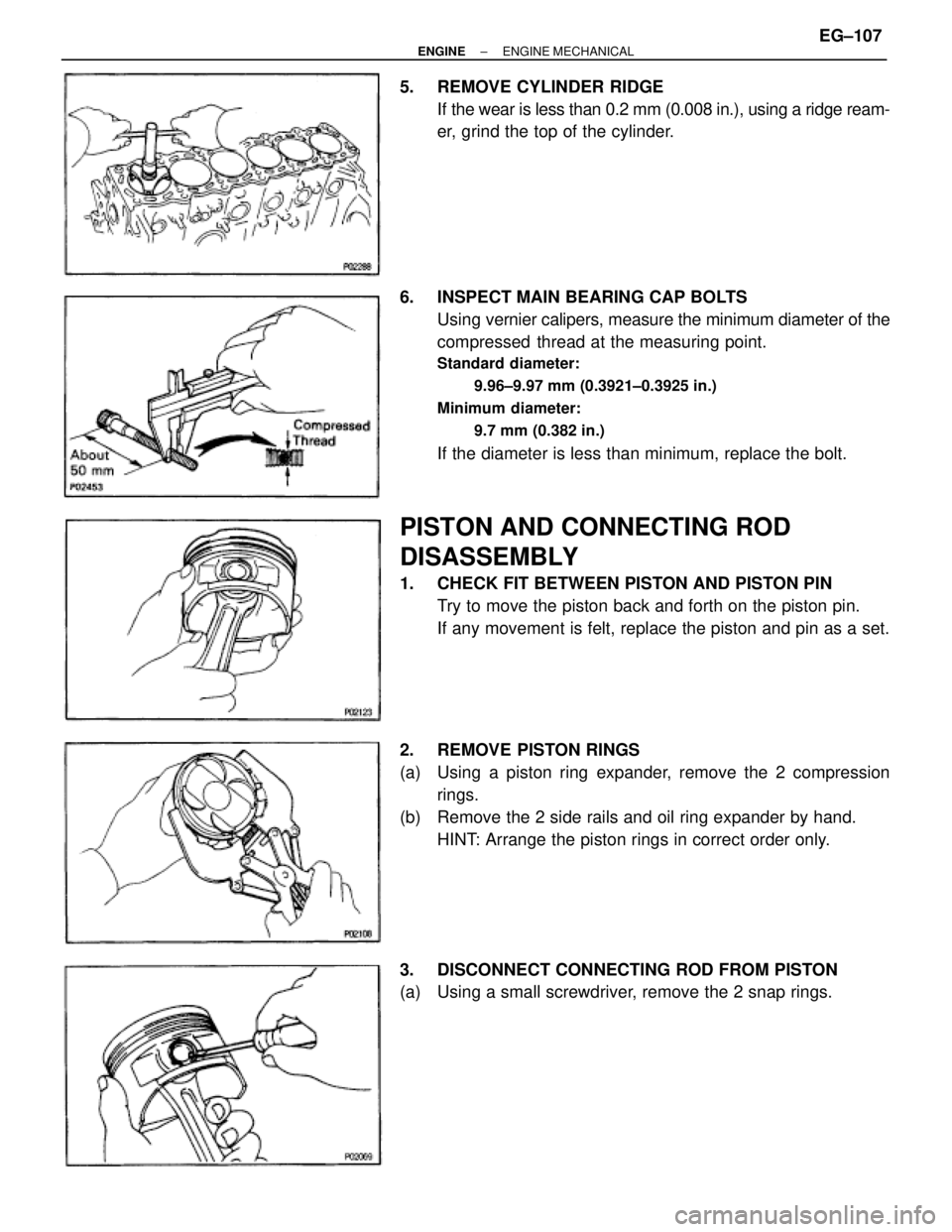
5. REMOVE CYLINDER RIDGE
If the wear is less than 0.2 mm (0.008 in.), using a ridge ream-
er, grind the top of the cylinder.
6. INSPECT MAIN BEARING CAP BOLTS
Using vernier calipers, measure the minimum diameter of the
compressed thread at the measuring point.
Standard diameter:
9.96±9.97 mm (0.3921±0.3925 in.)
Minimum diameter:
9.7 mm (0.382 in.)
If the diameter is less than minimum, replace the bolt.
PISTON AND CONNECTING ROD
DISASSEMBLY
1. CHECK FIT BETWEEN PISTON AND PISTON PIN
Try to move the piston back and forth on the piston pin.
If any movement is felt, replace the piston and pin as a set.
2. REMOVE PISTON RINGS
(a) Using a piston ring expander, remove the 2 compression
rings.
(b) Remove the 2 side rails and oil ring expander by hand.
HINT: Arrange the piston rings in correct order only.
3. DISCONNECT CONNECTING ROD FROM PISTON
(a) Using a small screwdriver, remove the 2 snap rings.
± ENGINEENGINE MECHANICALEG±107
Page 1422 of 2543
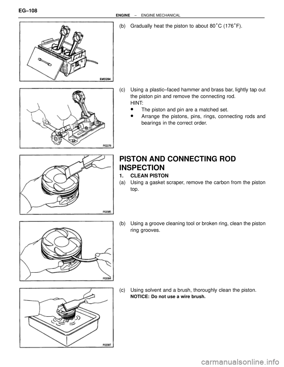
(b) Gradually heat the piston to about 80°C (176°F).
(c) Using a plastic±faced hammer and brass bar, lightly tap out
the piston pin and remove the connecting rod.
HINT:
wThe piston and pin are a matched set.
wArrange the pistons, pins, rings, connecting rods and
bearings in the correct order.
PISTON AND CONNECTING ROD
INSPECTION
1. CLEAN PISTON
(a) Using a gasket scraper, remove the carbon from the piston
top.
(b) Using a groove cleaning tool or broken ring, clean the piston
ring grooves.
(c) Using solvent and a brush, thoroughly clean the piston.
NOTICE: Do not use a wire brush.
EG±108± ENGINEENGINE MECHANICAL
Page 1423 of 2543

2. INSPECT PISTON
A. Inspect piston oil clearance
(a) Using a micrometer, measure the piston diameter at right
angles to the piston pin center line, 34 mm (1.34 in.) from the
piston head.
Piston diameter:
2JZ±GE
85.935±85.945 mm (3.3833±3.3837 in.)
2JZ±GTE
85.917±85.927 mm (3.3826±3.3830 in.)
(b) Measure the cylinder bore diameter in the thrust directions.
(See step 4 in cylinder block inspection)
(c) Subtract the piston diameter measurement from the cylinder
bore diameter measurement.
Standard oil clearance:
2JZ±GE
.055±0.078 mm (0.0022±0.0031 in.)
2JZ±GTE
.073±0.096 mm (0.0029±0.0038 in.)
Maximum oil clearance:
2JZ±GE
.10 mm (0.0039 in.)
2JZ±GTE
.12 mm (0.0047 in.)
If the oil clearance is greater than maximum, replace all the
6 pistons. If necessary, replace the cylinder block.
B. Inspect piston ring groove clearance
Using a feeler gauge, measure the clearance between new
piston ring and the wall of the piston ring groove.
Ring groove clearance:
No.1
2JZ±GE
0.011±0.070 mm (0.0004±0.0028 in.)
2JZ±GTE
0.040±0.080 mm (0.0016±0.0031 in.)
No.2
.030±0.070 mm (0.0012±0.0028 in.)
If the clearance is not as specified, replace the piston.
C. Inspect piston ring end gap
(a) Insert the piston ring into the cylinder bore.
(b) Using a piston, push the piston ring a little beyond the bottom
of the ring travel, 105 mm (4.13 in.) from the top of the cylinder
block.
± ENGINEENGINE MECHANICALEG±109
Page 1424 of 2543
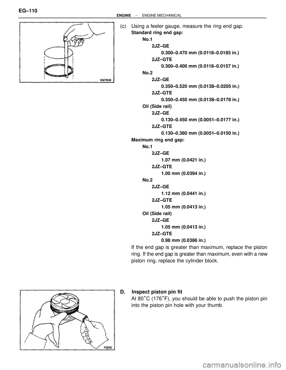
(c) Using a feeler gauge, measure the ring end gap.
Standard ring end gap:
No.1
2JZ±GE
0.300±0.470 mm (0.0118±0.0185 in.)
2JZ±GTE
0.300±0.400 mm (0.0118±0.0157 in.)
No.2
2JZ±GE
0.350±0.520 mm (0.0138±0.0205 in.)
2JZ±GTE
0.350±0.450 mm (0.0138±0.0178 in.)
Oil (Side rail)
2JZ±GE
0.130±0.450 mm (0.0051±0.0177 in.)
2JZ±GTE
0.130±0.380 mm (0.0051±0.0150 in.)
Maximum ring end gap:
No.1
2JZ±GE
1.07 mm (0.0421 in.)
2JZ±GTE
1.00 mm (0.0394 in.)
No.2
2JZ±GE
1.12 mm (0.0441 in.)
2JZ±GTE
1.05 mm (0.0413 in.)
Oil (Side rail)
2JZ±GE
1.05 mm (0.0413 in.)
2JZ±GTE
0.98 mm (0.0386 in.)
If the end gap is greater than maximum, replace the piston
ring. If the end gap is greater than maximum, even with a new
piston ring, replace the cylinder block.
D. Inspect piston pin fit
At 80°C (176°F), you should be able to push the piston pin
into the piston pin hole with your thumb. EG±110
± ENGINEENGINE MECHANICAL
Page 1425 of 2543
1041 W. 18th Street, Suite A210
Costa Mesa, California 92627
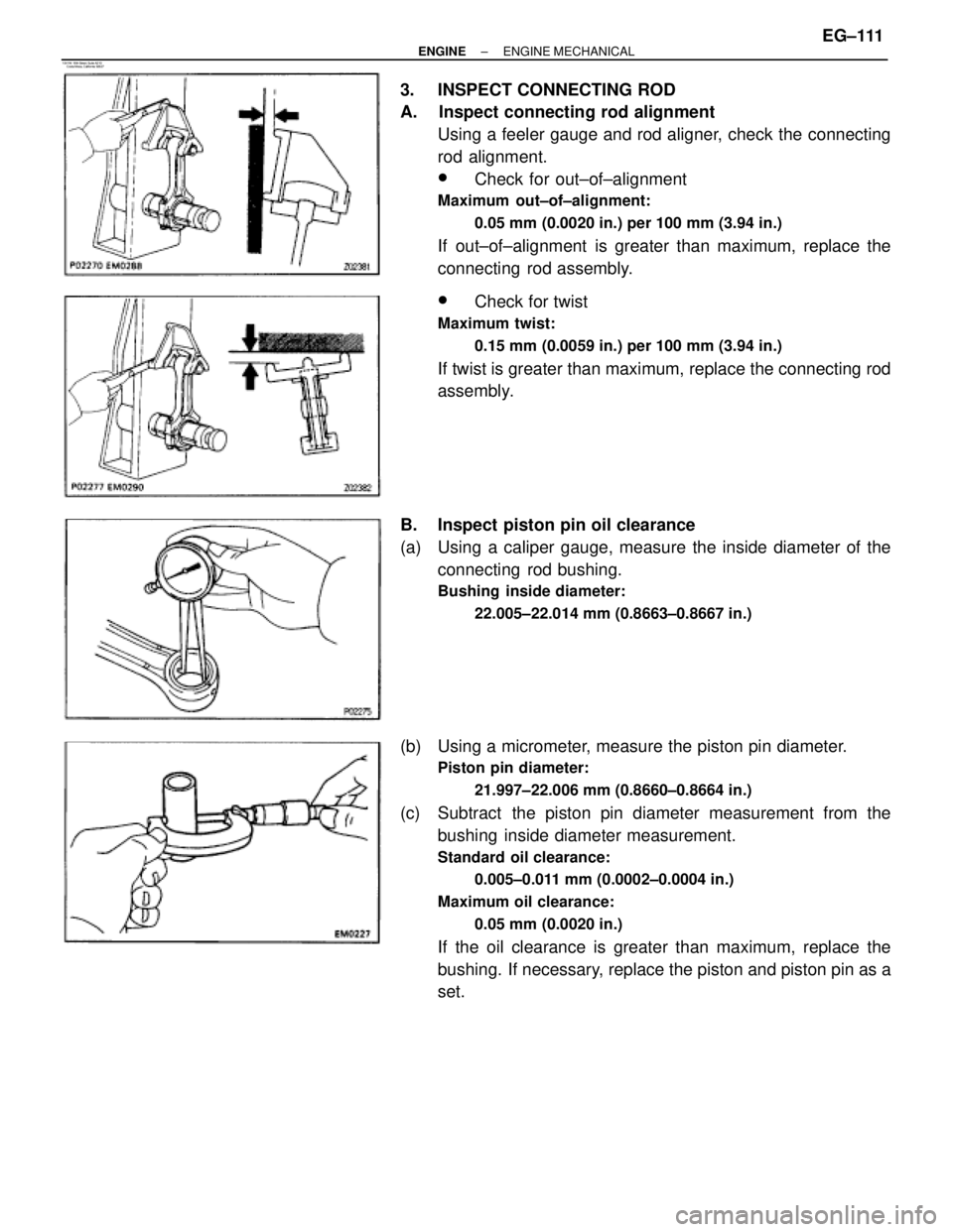
3. INSPECT CONNECTING ROD
A. Inspect connecting rod alignment
Using a feeler gauge and rod aligner, check the connecting
rod alignment.
wCheck for out±of±alignment
Maximum out±of±alignment:
0.05 mm (0.0020 in.) per 100 mm (3.94 in.)
If out±of±alignment is greater than maximum, replace the
connecting rod assembly.
wCheck for twist
Maximum twist:
0.15 mm (0.0059 in.) per 100 mm (3.94 in.)
If twist is greater than maximum, replace the connecting rod
assembly.
B. Inspect piston pin oil clearance
(a) Using a caliper gauge, measure the inside diameter of the
connecting rod bushing.
Bushing inside diameter:
22.005±22.014 mm (0.8663±0.8667 in.)
(b) Using a micrometer, measure the piston pin diameter.
Piston pin diameter:
21.997±22.006 mm (0.8660±0.8664 in.)
(c) Subtract the piston pin diameter measurement from the
bushing inside diameter measurement.
Standard oil clearance:
0.005±0.011 mm (0.0002±0.0004 in.)
Maximum oil clearance:
0.05 mm (0.0020 in.)
If the oil clearance is greater than maximum, replace the
bushing. If necessary, replace the piston and piston pin as a
set.
± ENGINEENGINE MECHANICALEG±111
Page 1426 of 2543
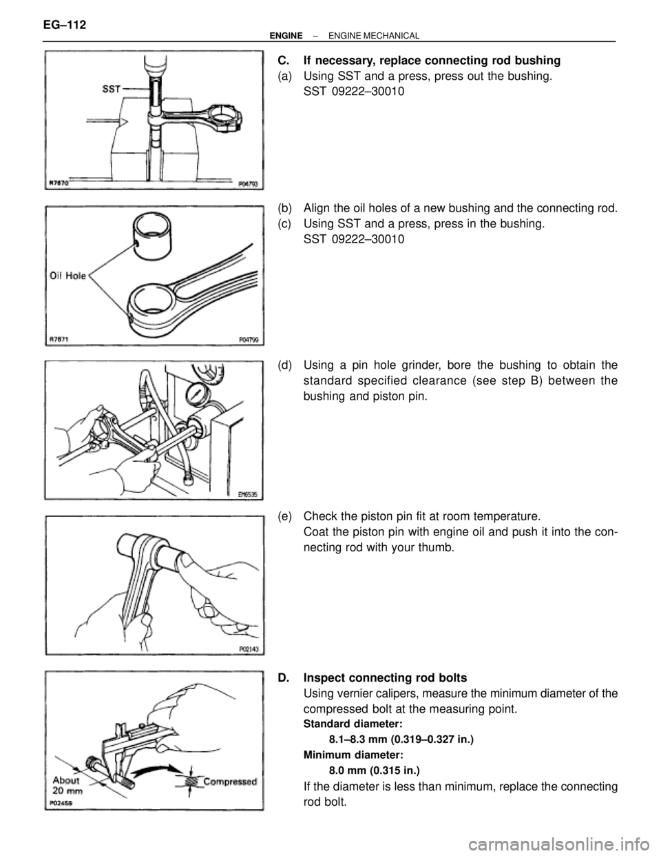
C. If necessary, replace connecting rod bushing
(a) Using SST and a press, press out the bushing.
SST 09222±30010
(b) Align the oil holes of a new bushing and the connecting rod.
(c) Using SST and a press, press in the bushing.
SST 09222±30010
(d) Using a pin hole grinder, bore the bushing to obtain the
standard specified clearance (see step B) between the
bushing and piston pin.
(e) Check the piston pin fit at room temperature.
Coat the piston pin with engine oil and push it into the con-
necting rod with your thumb.
D. Inspect connecting rod bolts
Using vernier calipers, measure the minimum diameter of the
compressed bolt at the measuring point.
Standard diameter:
8.1±8.3 mm (0.319±0.327 in.)
Minimum diameter:
8.0 mm (0.315 in.)
If the diameter is less than minimum, replace the connecting
rod bolt. EG±112
± ENGINEENGINE MECHANICAL
Page 1427 of 2543

CRANKSHAFT INSPECTION
1. INSPECT CRANKSHAFT FOR RUNOUT
(a) Place the crankshaft on V±blocks.
(b) Using a dial indicator, measure the circle runout at the center
journal.
Maximum circle runout:
0.06 mm (0.0024 in.)
If the circle runout is greater than maximum, replace the
crankshaft.
2. INSPECT MAIN JOURNALS AND CRANK PINS
(a) Using a micrometer, measure the diameter of each main
journal and crank pin.
Main journal diameter:
STD
61.984±62.000 mm (2.4403±2.4409 in.)
U/S 0.25
61.745±61.755 mm (2.4309±2.4313 in.)
Crank pin diameter:
STD
51.982±52.000 mm (2.0465±2.0472 in.)
U/S 0.25
51.745±51.755 mm (2.0372±2.0376 in.)
If the diameter is not as specified, check the oil clearance.
(See steps 3 and 6 in cylinder block disassembly)
(b) Ch e ck ea ch ma in jo u rn a l an d cra n k pin fo r taper and
out±of±round as shown.
Maximum taper and out±of round:
0.02 mm (0.0008 in.)
If the taper or out±of±round is greater than maximum, grind
or replace the crankshaft.
3. IF NECESSARY, GRIND AND HONE MAIN JOURNALS
AND/OR CRANK PINS
Grind and hone the main journals and/or crank pins to the fin-
ished undersized diameter (See procedure step 2).
Install new main journal and/or crank pin undersized bear-
ings.
± ENGINEENGINE MECHANICALEG±113
Page 1428 of 2543
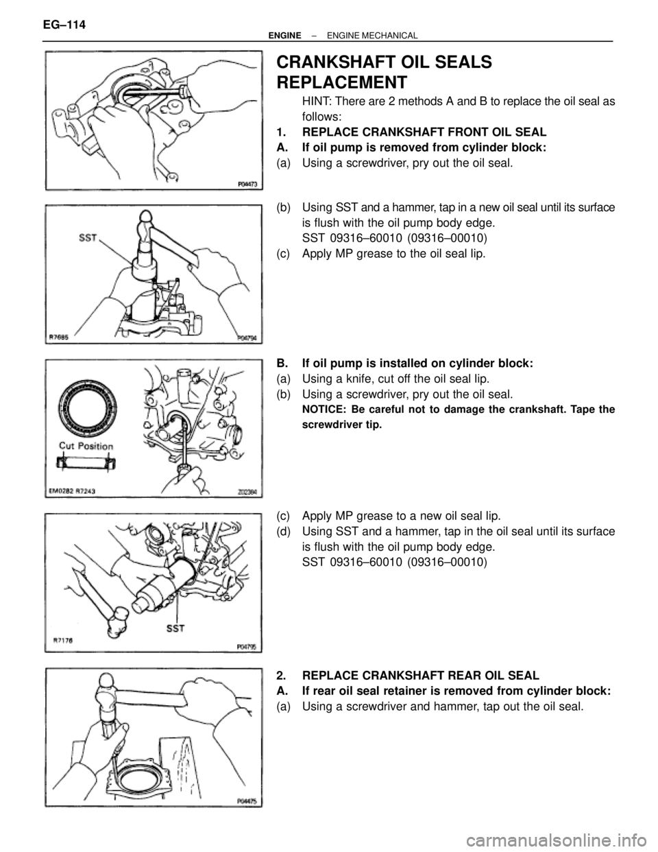
CRANKSHAFT OIL SEALS
REPLACEMENT
HINT: There are 2 methods A and B to replace the oil seal as
follows:
1. REPLACE CRANKSHAFT FRONT OIL SEAL
A. If oil pump is removed from cylinder block:
(a) Using a screwdriver, pry out the oil seal.
(b) Using SST and a hammer, tap in a new oil seal until its surface
is flush with the oil pump body edge.
SST 09316±60010 (09316±00010)
(c) Apply MP grease to the oil seal lip.
B. If oil pump is installed on cylinder block:
(a) Using a knife, cut off the oil seal lip.
(b) Using a screwdriver, pry out the oil seal.
NOTICE: Be careful not to damage the crankshaft. Tape the
screwdriver tip.
(c) Apply MP grease to a new oil seal lip.
(d) Using SST and a hammer, tap in the oil seal until its surface
is flush with the oil pump body edge.
SST 09316±60010 (09316±00010)
2. REPLACE CRANKSHAFT REAR OIL SEAL
A. If rear oil seal retainer is removed from cylinder block:
(a) Using a screwdriver and hammer, tap out the oil seal. EG±114
± ENGINEENGINE MECHANICAL
Page 1429 of 2543
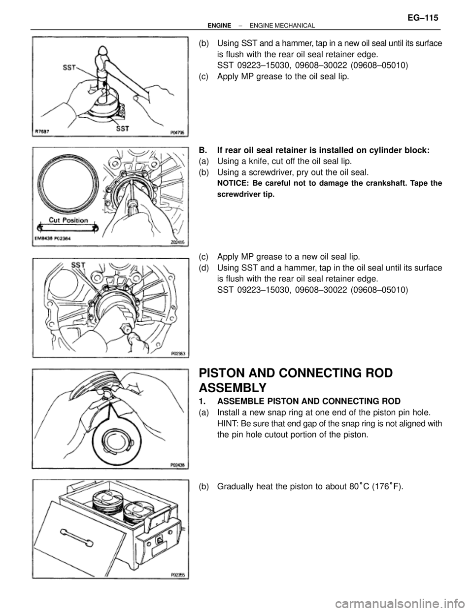
(b) Using SST and a hammer, tap in a new oil seal until its surface
is flush with the rear oil seal retainer edge.
SST 09223±15030, 09608±30022 (09608±05010)
(c) Apply MP grease to the oil seal lip.
B. If rear oil seal retainer is installed on cylinder block:
(a) Using a knife, cut off the oil seal lip.
(b) Using a screwdriver, pry out the oil seal.
NOTICE: Be careful not to damage the crankshaft. Tape the
screwdriver tip.
(c) Apply MP grease to a new oil seal lip.
(d) Using SST and a hammer, tap in the oil seal until its surface
is flush with the rear oil seal retainer edge.
SST 09223±15030, 09608±30022 (09608±05010)
PISTON AND CONNECTING ROD
ASSEMBLY
1. ASSEMBLE PISTON AND CONNECTING ROD
(a) Install a new snap ring at one end of the piston pin hole.
HINT: Be sure that end gap of the snap ring is not aligned with
the pin hole cutout portion of the piston.
(b) Gradually heat the piston to about 80°C (176°F).
± ENGINEENGINE MECHANICALEG±115
Page 1430 of 2543
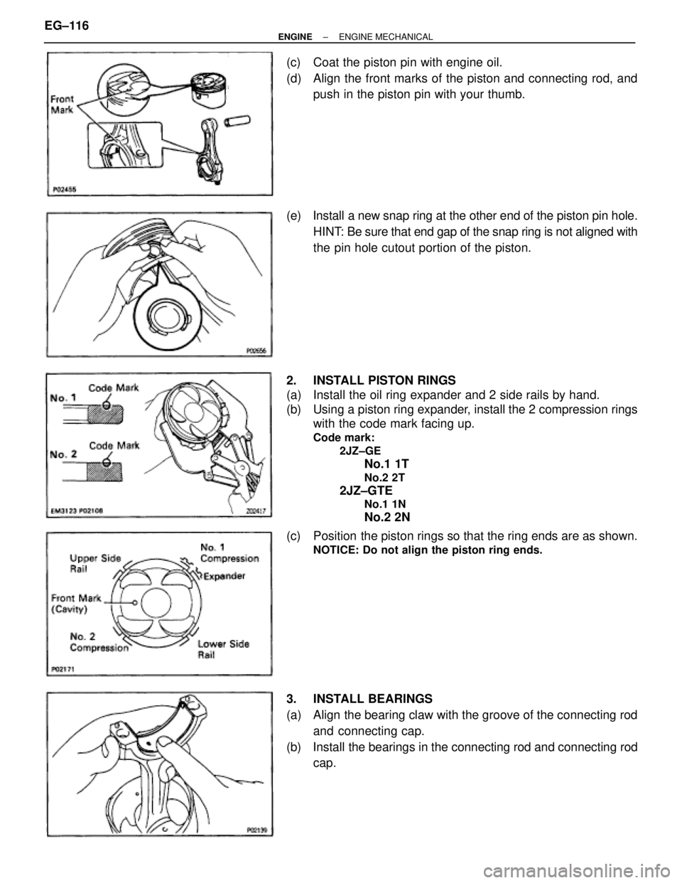
(c) Coat the piston pin with engine oil.
(d) Align the front marks of the piston and connecting rod, and
push in the piston pin with your thumb.
(e) Install a new snap ring at the other end of the piston pin hole.
HINT: Be sure that end gap of the snap ring is not aligned with
the pin hole cutout portion of the piston.
2. INSTALL PISTON RINGS
(a) Install the oil ring expander and 2 side rails by hand.
(b) Using a piston ring expander, install the 2 compression rings
with the code mark facing up.
Code mark:
2JZ±GE
No.1 1T
No.2 2T
2JZ±GTE
No.1 1N
No.2 2N
(c) Position the piston rings so that the ring ends are as shown.
NOTICE: Do not align the piston ring ends.
3. INSTALL BEARINGS
(a) Align the bearing claw with the groove of the connecting rod
and connecting cap.
(b) Install the bearings in the connecting rod and connecting rod
cap. EG±116
± ENGINEENGINE MECHANICAL