lock TOYOTA TERCEL 1985 Repair Manual
[x] Cancel search | Manufacturer: TOYOTA, Model Year: 1985, Model line: TERCEL, Model: TOYOTA TERCEL 1985Pages: 885, PDF Size: 64.52 MB
Page 487 of 885
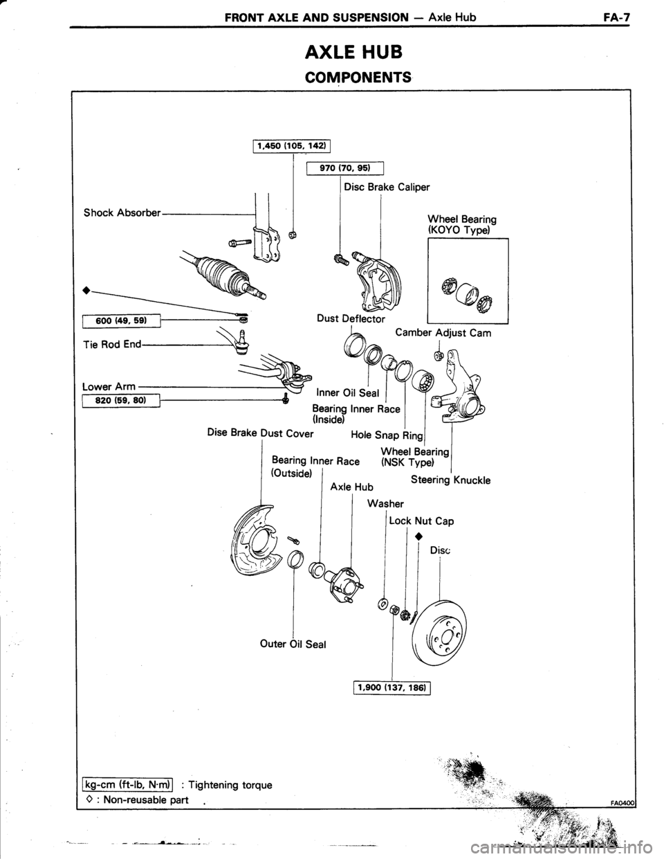
FRONT AXLE AND SUSPENSION - Axle HubFA.7
AXLE HUB
COMPONENTS
1,450 (105, 142)
Disc Brake Caliper
shocknusoruer-----'1 I I i I wheet Bearins
ntdliff*>> q$J d^%J- |
*@r
rie Rod r"o \E
h^
t.''"'lo:'t cam
:-\^'
*9@n^6g1'
i:T:":it:i Y9J'A-
ffi31?yrnnerRacel l*ryDise Brake Dust cover t"'" *1":iHJ"r,""l
Lt^:::l1l"ner Race (NSK rype) -l
a?6,
I
iOuter Oit Seal
Lock Nut Cap
ir
/1"i"
Y&r-A
lSU
Ikg-cm (ft-lb, N.m)l : Tightening torque
O : Non-reusable part
Page 488 of 885
nIFA.8FRONT AXLE AND SUSPENSION- Axle Hub
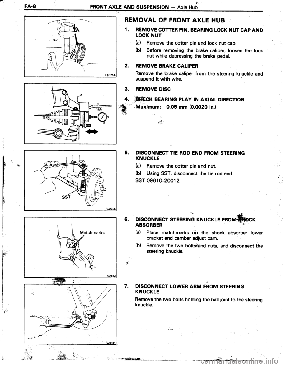
REMOVAL OF FRONT AXLE HUB
1. REMOVE COTTER PIN. BEARING LOCK NUT CAP AND
LOCK NUT
(a) Remove the cotter pin and lock nut cap.
(b) Before removing the brake caliper, loosen the lock
nut while depressing the brake pedal.
2. REMOVE BRAKE CALIPER
Remove the brake caliper from the steering knuckle and
suspend it with wire.
REMOVE DISC
*fi*frcr BEARTNG pLAy rN AxtAL DtREcnoN
'' Maximum: 0.05 mm (O.OO2O in.l
5. DISCONNECT TIE ROD END FROM STEERING
KNUCKLE
(d Remove the cotter pin and nut.
(b) Using SST, disconnect the tie rod end.
ssT 09610-20012
(Le rnorrn*fucr6. DISCONNECT STEERING KNUCI
nC
t
rY
I
ItI
Ili
,
)t-5f'
ABSORBER
(d Place matchmarks on the shock absorber lower
bracket and camber adjust cam.
(b) Remove the two boltsend nuts, and disconnect the
steering knuckle.
DISCONNECT LOWER ARM FiOM STEERING
KNUCKLE
Remove the two bolts holding the balljoint to the steering
knuckle.
7.
.. ...t
3.
4.
".-*ffi,i.,.*f.isEl;-*r: .
Page 491 of 885
_ l +l i'-:r': : '
FRONT AXLE AND SUSPENSION - Axle HubFA-l1
3.3 -+
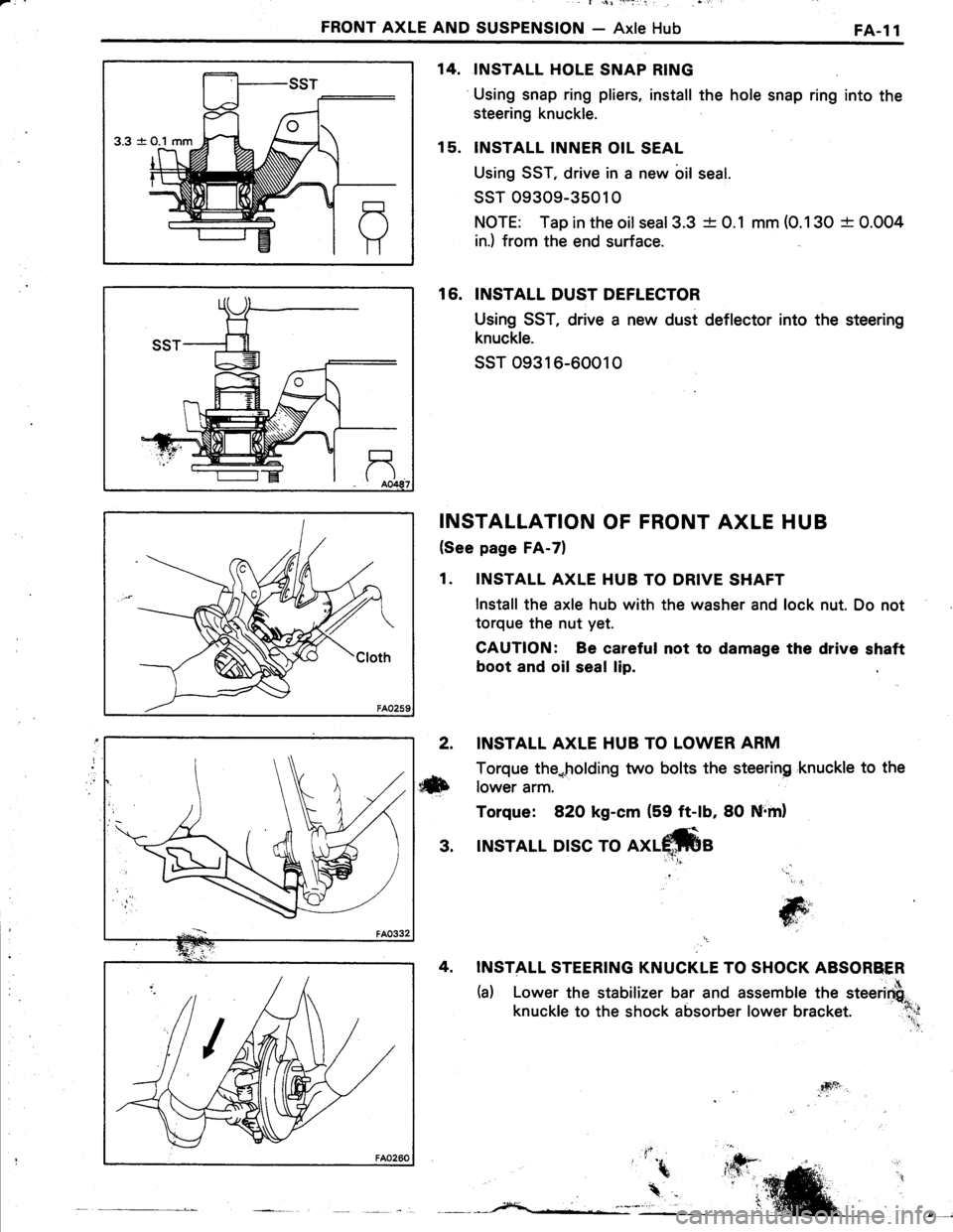
INSTALL HOLE SNAP RING
Using snap ring pliers, install the hole snap ring into the
steering knuckle.
INSTALL INNER OIL SEAL
Using SST, drive in a new bil seal.
ssT 09309-35010
NOTE: Tap in the oilseal3.3 -t- 0.1 mm (O.130 + 0.004
in.) from the end surface.
16. INSTALL DUST DEFLECTOR
Using SST, drive a new dust deflector into the steering
knuckle.
ssT o9316-60010
INSTALLATION OF FRONT AXLE HUB
(See page FA-7)
1. INSTALL AXLE HUB TO DRIVE SHAFT
lnstall the axle hub with the washer and lock nut. Do not
torque the nut yet.
CAUTION: Be careful not to damage the drive shaft
boot and oil seal lip.
14.
15.
2. INSTALL AXLE HUB TO LOWER ARM
Torque the*holding two bolts the steering 'knuckle to the
ilxb rower arm.
Torque: 82O kg-cm (59 ft-lb, 80 Nrml
3. INSTALL DISC TO
INSTALL STEERING KNUCKLE TO SHOCK ABSORBER
(a) Lower the stabilizer bar and assemble the steerirfi"
knuckle to the shock absorber lower bracket. :l;;
'' .!
jG;','
T6i'
4sft
Page 492 of 885
'l
FA..12FRONT AXLE AND SUSPENSION - Axle Hub
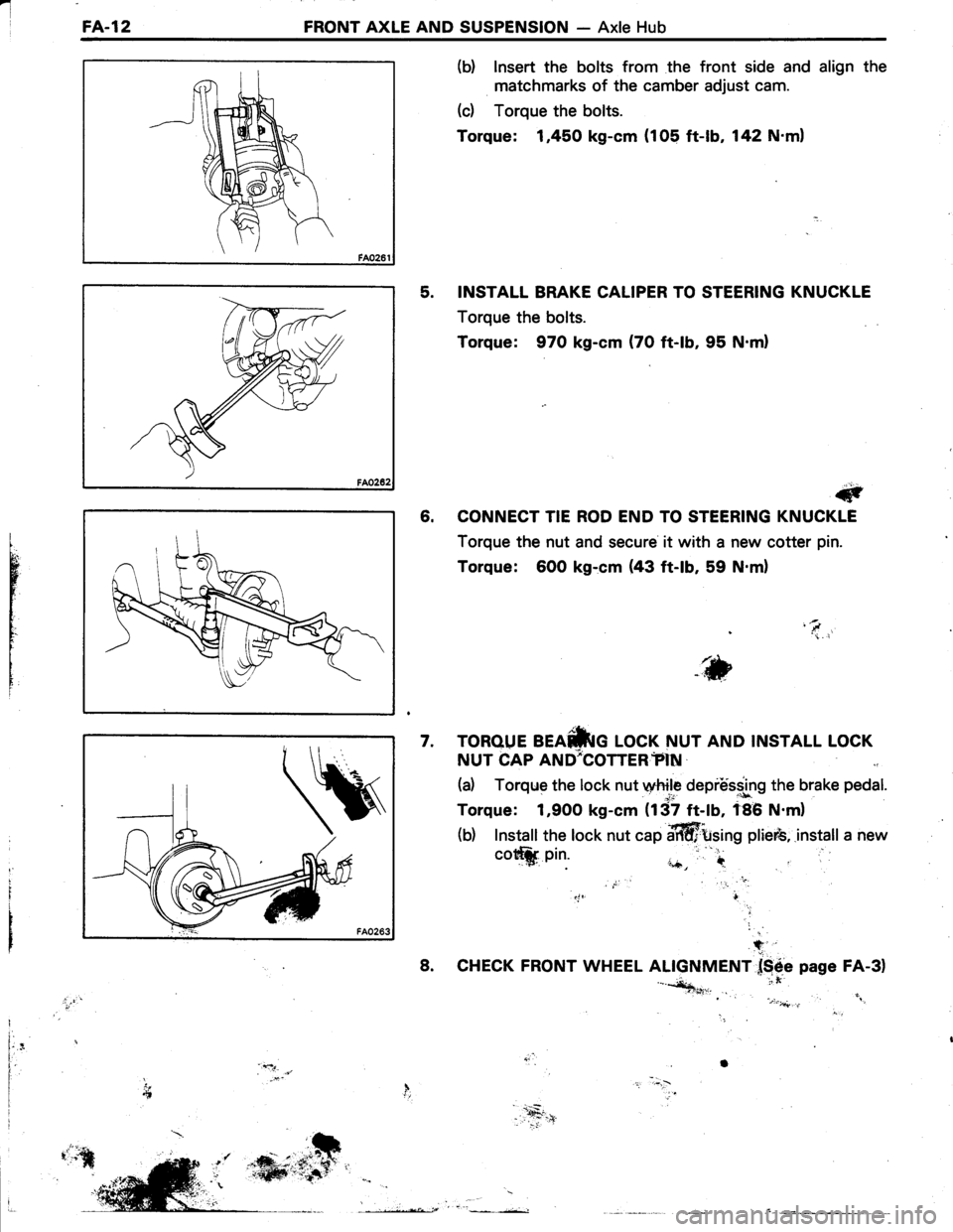
(b) lnsert the bolts from the front side and align the
matchmarks of the camber adjust cam.
(c) Torque the bolts.
Torque: 1,450 kg-cm (105 ft-lb, 142 N'ml
5. INSTALL BRAKE CALIPER TO STEERING KNUCKLE
Torque the bolts.
Torque: 970 kg-cm (70 ft-lb, 95 N.ml
#
6. CONNECT TIE ROD END TO STEERING KNUCKLE
Torque the nut and secure it with a new cotter pin.
Torque: 6O0 kg:cm (43 ft-lb, 59 N.m)
'\i. i
tr,bWVii
i
TOROUE BEAfriG LOCK NUT AND INSTALL LOCK
NUT CAP AND;COTTER?IN
(a) Torqrle the lock nut wtrile depiUs.s.lng the brake pedal.
Torque: 1,900 kg-cm (137 ft-lb, f86 N.m)
(b) Install the lock nut cap affittsing plieib,.install a new
7.
cott*. pin.
8.
+
CHECK FRONT WHEEL ALIGNMENT f$6e page FA-3)'-*+***n,. it'., . .i .:)".4..,,'i".: "
Il.I
f,'l.
Page 498 of 885
I
FA-l8FRONT AXLE AND SUSPENSION - Front Drive Shaft
Length
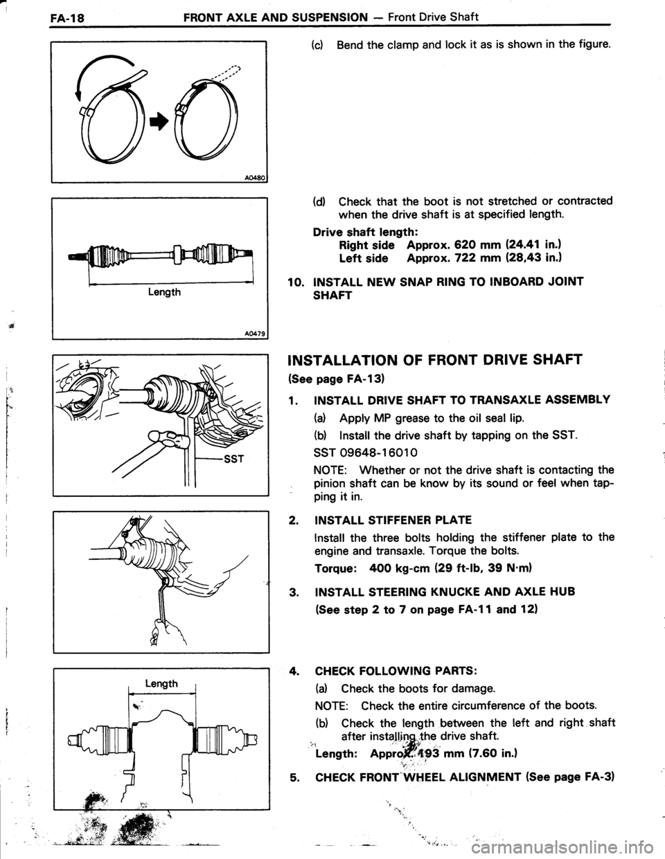
(c) Bend the clamp and lock it as is shown in the figure.
(d) Check that the boot is not stretched or contracted
when the drive shaft is at specified length.
Drive shaft length:
Right side Approx. 620 mm 124.41 in.l
Left side Approx. 722 mm (28,43 in.)
10. INSTALL NEW SNAP RING TO INBOARD JOINT
SHAFT
INSTALLATION OF FRONT DRIVE SHAFT
(See page FA-l3)
1. INSTALL DRIVE SHAFT TO TRANSAXLE ASSEMBLY
(a) Apply MP grease to the oil seal lip.
(b) lnstall the drive shaft by tapping on the SST.
ssT 09648-16010
NOTE: Whether or not the drive shaft is contacting the
pinion shaft can be know by its sound or feel when tap-
ping it in.
INSTALL STIFFENER PLATE
lnstall the three bolts holding the stiffener plate to the
engine and transaxle. Torque the bolts.
Torque: 400 kg-cm (29 ft-lb, 39 N'm)
INSTALL STEERING KNUCKE AND AXLE HUB
(See step 2 to 7 on page FA-l1 and 12)
4. CHECK FOLLOWING PARTS:
(d Check the boots for damage.
NOTE: Check the entire circumference of the boots.
(b) Check the length between the left and right shaft
after installinq,.the drive shaft.i": ' -|*itLength: Approjff{93 mm (7.60 in.)
5. CHECK FRONT"WHEEL ALIGNMENT (See page FA-31
2.
3.
"1.
Page 503 of 885
FRONT AXLE AND SUSPENSION - Front SuspensionFA-23
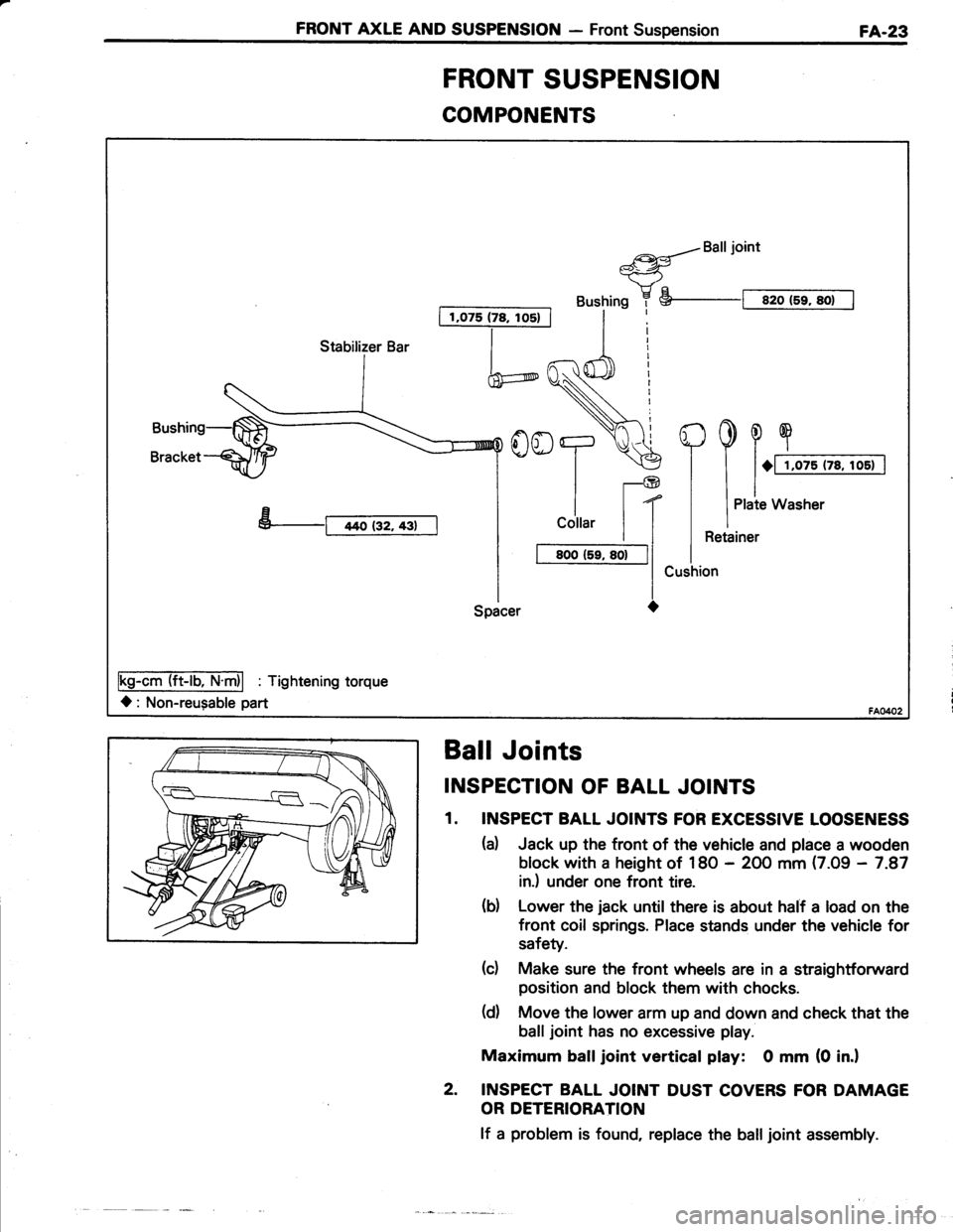
COMPONENTS
I 1,075 (78, los) |
a{Balljoint*-<-ry"
Bushing 7 S--t sro (5r, sot I
h
YooT.\€
ll-@
| | t(
I
cottar | |
I t BooCr, so-|l
l-lSpacer O
Fs-AmTliET'fri| : Tishtenins torque
l: Non-reugable part
Stabilizer Bar
FRONT SUSPENSION
Ball Joints
INSPECTION OF BALL JOINTS
1. INSPECT BALL JOINTS FOR EXCESSIVE LOOSENESS
(d Jack up the tront of the vehicle and place a wooden
block with a height of 18O - 2OO mm (7.09 - 7.87
in.) under one front tire.
(d Lower the jack until there is about half a load on the
front coil springs. Place stands under the vehicle for
safety.
(c) Make sure the front wheels are in a straightforward
position and block them with chocks.
(d) Move the lower arm up and down and check that the
balljoint has no excessive play.
Maximum balljoint vertical play: 0 mm (0 in.l
2. INSPECT BALL JOINT DUST COVERS FOR DAMAGE
OR DETERIORATION
lf a problem is found, replace the balljoint assembly.
Page 513 of 885
REAR AXLE AND SUSPENSION - Rear Axle Hub and Carrier (FWD) RA-s
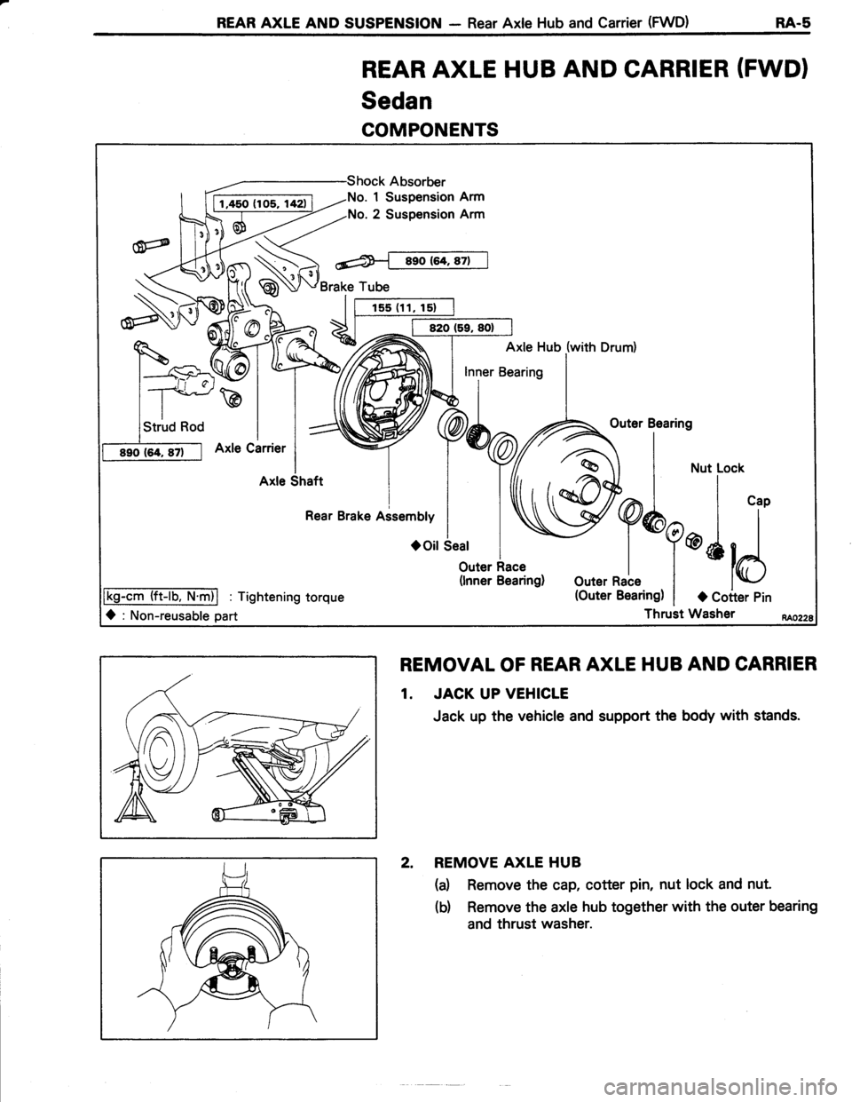
REAR AXLE HUB AND CARRIER (FWDI
Sedan
COMPONENTS
REMOVAL OF REAR AXLE HUB AND CARRIER
1. JACK UP VEHICLE
Jack up the vehicle and support the body with stands.
2. REMOVE AXLE HUB
(a) Remove the cap, cotter pin, nut lock and nut.
(b) Remove the axle hub together with the outer bearing
and thrust washer.
No. 1 Suspension Arm
No. 2 Suspension Arm
Brake Tube
Axle Hub (with Drum)
\,outer
Bearins
a | *u..o"*
W^I | ',,
Y
Y*q@l l
outernale t
*ld
(Outer Bearing) | a Coiter Pin
Thruit Washer
Outer Race(lnner Bearing)
lkg-cm (ft-lb. N.m)l : Tightening torque
O : Non-reusable part
Page 518 of 885
r.1
E4-10 REAR AXLE AND SUSPENSION - Rear Axle Hub and Canier (FWD)
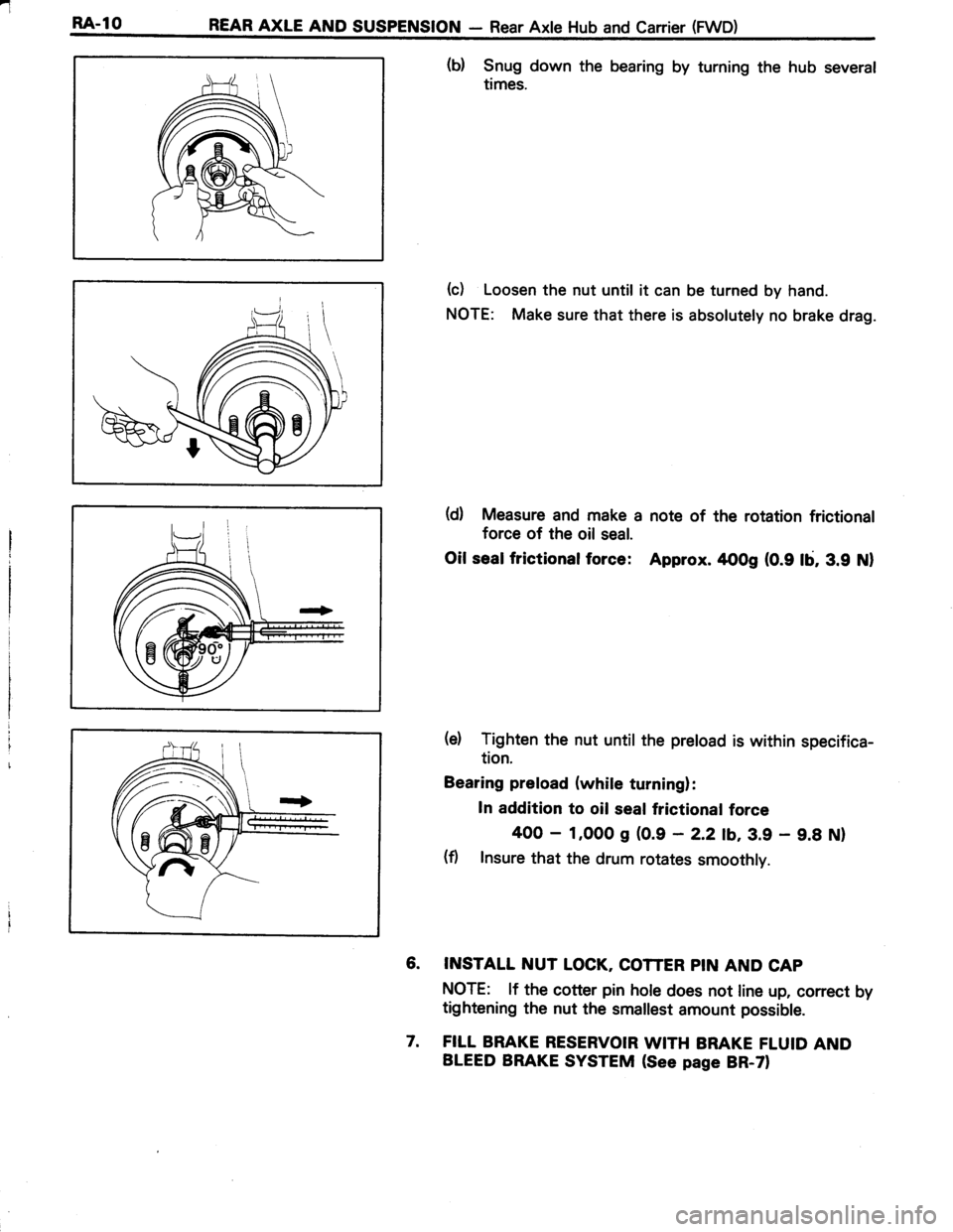
(b) Snug down the bearing by turning the hub several
times.
(c) Loosen the nut until it can be turned by hand.
NOTE: Make sure that there is absolutely no brake drag.
(d) Measure and make a note of the rotation frictional
force of the oil seal.
Oil sealfrictionalforce: Approx. rtoog (0.9 lb, 3.9 Nl
(e) Tighten the nut until the preload is within specifica-
tion.
Bearing preload (while turning):
In addition to oil seal frictional force
400 - 1,000 g (0.9 - 2.2 tb,3.9 - 9.8 Nl
(fl Insure that the drum rotates smoothly.
6. INSTALL NUT LOCK, COTTER PIN AND CAP
NOTE: lf the cotter pin hole does not line up, correct by
tightening the nut the smallest amount possible.
7. FILL BRAKE RESERVOIR WITH BRAKE FLUID AND
BLEED BRAKE SYSTEM (See page BR-ZI
Page 535 of 885
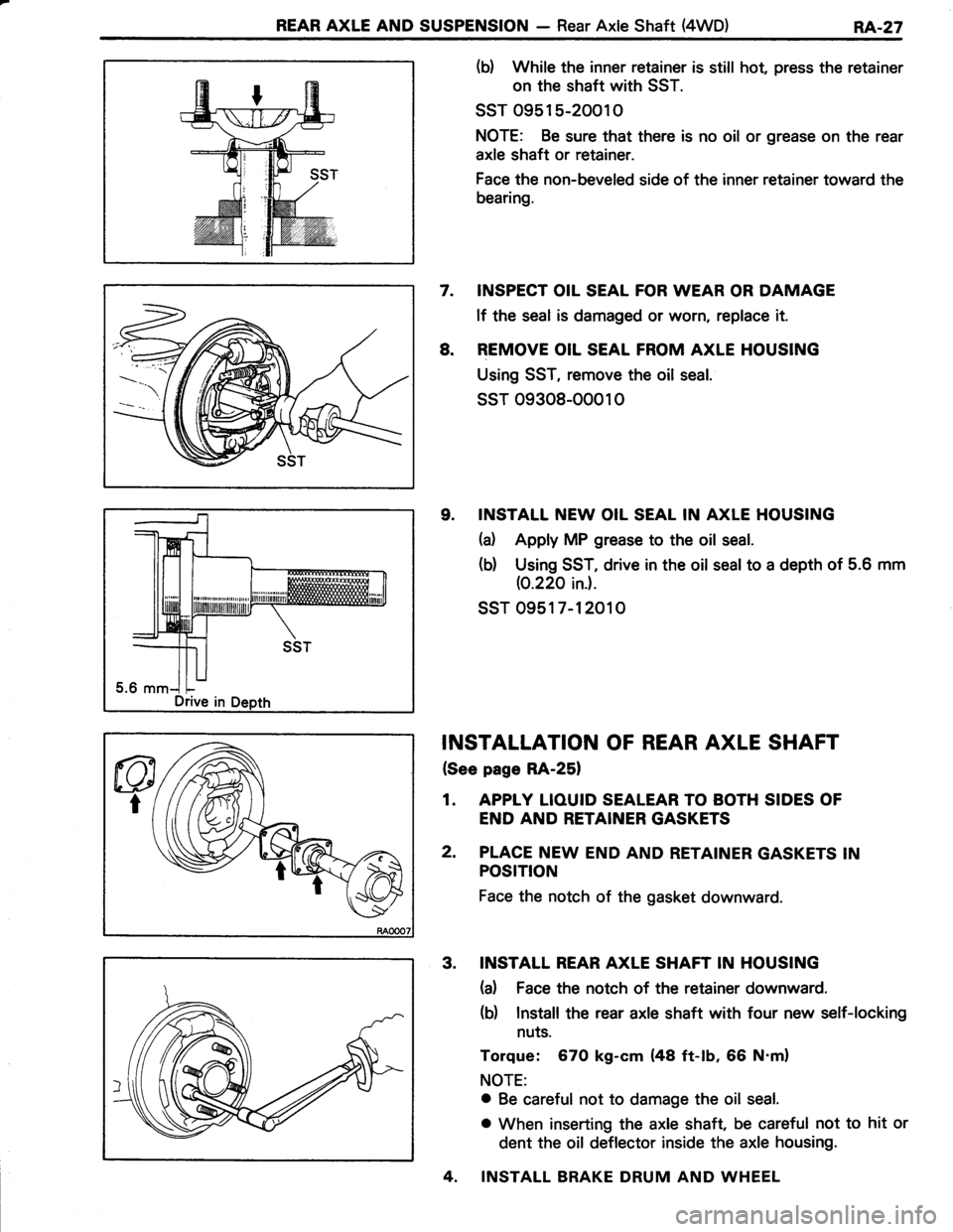
REAR AXLE AND SUSPENSION - Rear Axle Shaft (4WD)RA..27
(b) While the inner retainer is still hot, press the retainer
on the shaft with SST.
ssT 0951 5-20010
NOTE: Be sure that there is no oil or grease on the rear
axle shaft or retainer.
Face the non-beveled side of the inner retainer toward the
bearing.
7. INSPECT OIL SEAL FOR WEAR OR DAMAGE
lf the seal is damaged or worn, replace it.
8. REMOVE OIL SEAL FROM AXLE HOUSING
Using SST, remove the oil seal.
ssT 09308-00010
9. INSTALL NEW OIL SEAL IN AXLE HOUSING
(d Apply MP grease to the oil seal.
(b) Using SST, drive in the oil seal to a depth of 5.6 mm
(0.220 ini.
ssr 0951 7-12010
INSTALLATION OF REAR AXLE SHAFT
{See page RA-25}
1. APPIY LIOUID SEALEAR TO BOTH SIDES OF
END AND RETAINER GASKETS
2. PLACE NEW END AND RETAINER GASKETS IN
POSTTtON
Face the notch of the gasket downward.
3. INSTALL REAR AXLE SHAFT IN HOUSING
(a) Face the notch of the retainer downward.
(b) Install the rear axle shaft with four new self-locking
nuts.
Torque: 670 kg-cm (48 ft-tb, 66 N'm)
NOTE:
o Be careful not to damage the oil seal.
o When inserting the axle shaft, be careful not to hit or
dent the oil deflector inside the axle housing.
4. INSTALL BRAKE DRUM AND WHEEL
Drive in
Page 539 of 885
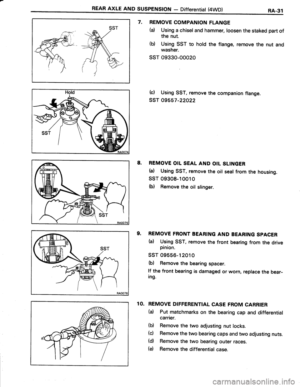
REAR AXLE AND SUSPENSTON - Differentiat (4WD)RA-31
7. REMOVE COMPANION FLANGE
(a) Using a chisel and hammer, loosen the staked part of
the nut.
(b) Using SST to hold the flange, remove the nut and
washer.
ssT 09330-00020
b) Using SST, remove the companion flange.
ssT 09557-22022
8. REMOVE OIL SEAL AND OIL SLTNGER
h) Using SST, remove the oil seal from the housing.
ssr 09308-10010
(b) Remove the oil slinger.
9. REMOVE FRONT BEARING AND BEARING SPACER
(a) Using SST, remove the front bearing from the drivepinion.
ssT 09556-12010
(b) Remove the bearing spacer.
lf the front bearing is damaged or worn, replace the bear-ing.
10. REMOVE DIFFERENTIAL CASE FROM CARRIER
(d Put matchmarks on the bearing cap and differential
carrier.
(b) Remove the two adjusting nut locks.
(c) Remove the two bearing caps and two adjusting nuts.
(d) Remove the two bearing outer races.
(d Remove the differential case.