Odo TOYOTA YARIS 2022 Owners Manual
[x] Cancel search | Manufacturer: TOYOTA, Model Year: 2022, Model line: YARIS, Model: TOYOTA YARIS 2022Pages: 590, PDF Size: 128.6 MB
Page 46 of 590

44
HV Owner's Manual_Europe_M52N30_en
1-1. For safe use
Exhaust gas precautions
Harmful substance to the
human body is included in
exhaust gases if inhaled.
WARNING
Exhaust gases include harmful car-
bon monoxide (CO), which is color- less and odorless. Observe the following precautions.
Failure to do so may cause exhaust gases enter the vehicle and may lead to an accident caused by light-
headedness, or may lead to death or a serious health hazard.
■Important points while driving
●Keep the back door closed.
●If you smell exhaust gases in the vehicle even when the back door is closed, open the windows and have
the vehicle inspected at any autho- rized Toyota retailer or Toyota authorized repairer, or any reliable
repairer as soon as possible.
■When parking
●If the vehicle is in a poorly venti- lated area or a closed area, such as a garage, stop the hybrid system.
●Do not leave the vehicle with the hybrid system on for a long time.
If such a situation cannot be avoided, park the vehicle in an open space and ensure that
exhaust fumes do not enter the vehicle interior.
●Do not leave the hybrid system operating in an area with snow build-up, or where it is snowing. If
snowbanks build up around the vehicle while the hybrid system is operating, exhaust gases may col-
lect and enter the vehicle.
■Exhaust pipe
The exhaust system needs to be checked periodically. If there is a hole
or crack caused by corrosion, dam- age to a joint or abnormal exhaust noise, be sure to have the vehicle
inspected and repaired by any autho- rized Toyota retailer or Toyota autho-rized repairer, or any reliable repairer.
Page 96 of 590
94
HV Owner's Manual_Europe_M52N30_en
2-1. Instrument cluster
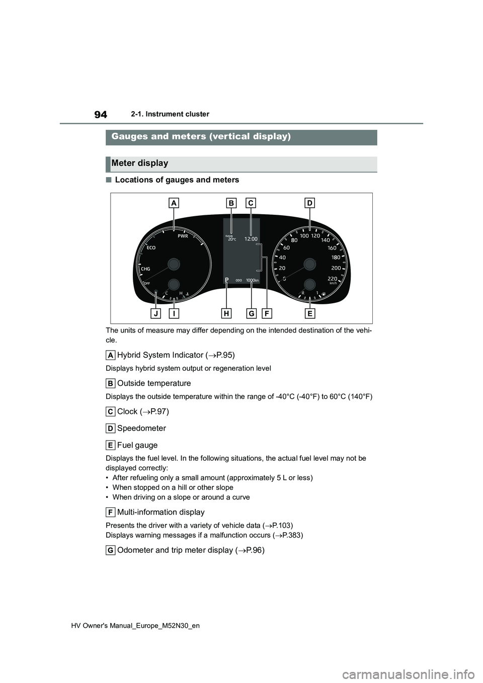
■Locations of gauges and meters
The units of measure may differ depending on the intended destination of the vehi-
cle.
Hybrid System Indicator ( P. 9 5 )
Displays hybrid system output or regeneration level
Outside temperature
Displays the outside temperature within the range of -40°C (-40°F) to 60°C (140°F)
Clock (P.97)
Speedometer
Fuel gauge
Displays the fuel level. In the following situations, the actua l fuel level may not be
displayed correctly:
• After refueling only a small amount (approximately 5 L or less )
• When stopped on a hill or other slope
• When driving on a slope or around a curve
Multi-information display
Presents the driver with a variety of vehicle data ( P.103)
Displays warning messages if a malfunction occurs ( P.383)
Odometer and trip meter display (P. 9 6 )
Gauges and meters (vertical display)
Meter display
Page 98 of 590
96
HV Owner's Manual_Europe_M52N30_en
2-1. Instrument cluster
may be malfunctioning. Take your
vehicle to any authorized Toyota retailer or Toyota authorized repairer, or any reliable repairer.
■Fuel gauge and driving range dis-
play
The fuel gauge and driving range dis- play are linked. If the fuel gauge and
driving range display do not update after refueling a small amount, they can be updated by performing the following pro-
cedure:
1 Stop the vehicle on a level surface.
Wait until the fuel in the fuel tank stabi- lizes.
2 Press the display change button to
change the odometer and trip meter display to the odometer.
3 Turn the power switch off.
4 While pressing and holding the dis- play change button, turn the power
switch to ON.
5 Continue holding the display change button for approximately 5 seconds.
Release the button when the odometer
begins blinking.
Updating will be complete when the odometer blinks for approximately 5
seconds and then returns to the normal display.
■Liquid crystal display
P. 1 0 4
■Customization
The gauges and meters can be custom-
ized in of the multi-information dis-
play. ( P.431)
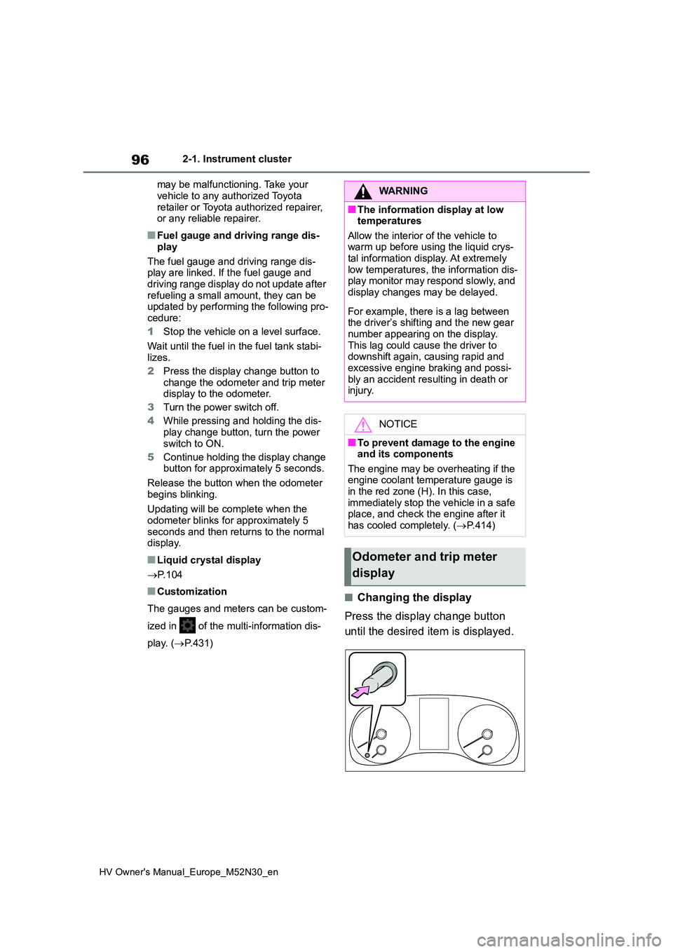
■Changing the display
Press the display change button
until the desired item is displayed.
WARNING
■The information display at low temperatures
Allow the interior of the vehicle to warm up before using the liquid crys-tal information display. At extremely
low temperatures, the information dis- play monitor may respond slowly, and display changes may be delayed.
For example, there is a lag between the driver’s shifting and the new gear
number appearing on the display. This lag could cause the driver to downshift again, causing rapid and
excessive engine braking and possi- bly an accident resulting in death or injury.
NOTICE
■To prevent damage to the engine and its components
The engine may be overheating if the engine coolant temperature gauge is in the red zone (H). In this case,
immediately stop the vehicle in a safe place, and check the engine after it
has cooled completely. ( P.414)
Odometer and trip meter
display
Page 99 of 590
97
2
HV Owner's Manual_Europe_M52N30_en
2-1. Instrument cluster
Vehicle status information and indicators
■Display items
Odometer
Displays the total distance the vehicle
has been driven.
Trip meter A/Trip meter B
Displays the distance the vehicle has
been driven since the meter was last
reset. Trip meters A and B can be used
to record and display different distances
independently.
To reset, display the desired trip meter
and press and hold the display change
button.
Distance until next engine oil
change
Displays the distance the vehicle can
be driven until an oil change is neces-
sary.
The distance until the next engine oil
change will also be displayed in the fol-
lowing situations:
• When the power switch is turned to
ON.
• When a warning message indicating
that oil maintenance should be per-
formed soon or is required is dis-
played.
• Resetting: P. 3 2 7
■Adjusting the minute to “00”
1 Press or to select of
the multi-information display.
2 Press or to select “Clock
: 00”.
Press the to set the clock to the
beginning of the nearest hour.
e.g.
1:00 to 1:29 1:00
1:30 to 1:59 2:00
■Changing the clock
1 Press or to select of
the multi-information display.
2 Press or to select “Clock
: 00”.
3 Press and hold the .
4 Press or to select an
item to be changed.
5 Press or to change the
setting.
The following can be changed:
12-hour/24-hour format
Hour
Minute
The clocks on the following can be
adjusted on the multimedia system
screen.
Multi-information display
Multimedia system screen
For details, refer to “Navigation and
multimedia system Owner’s man-
Adjusting the clock (vehi-
cles without 7-inch/8-inch
display multimedia system)
Adjusting the clock (vehi-
cles with 7-inch/8-inch dis-
play multimedia system)
Page 101 of 590
99
2
HV Owner's Manual_Europe_M52N30_en
2-1. Instrument cluster
Vehicle status information and indicators
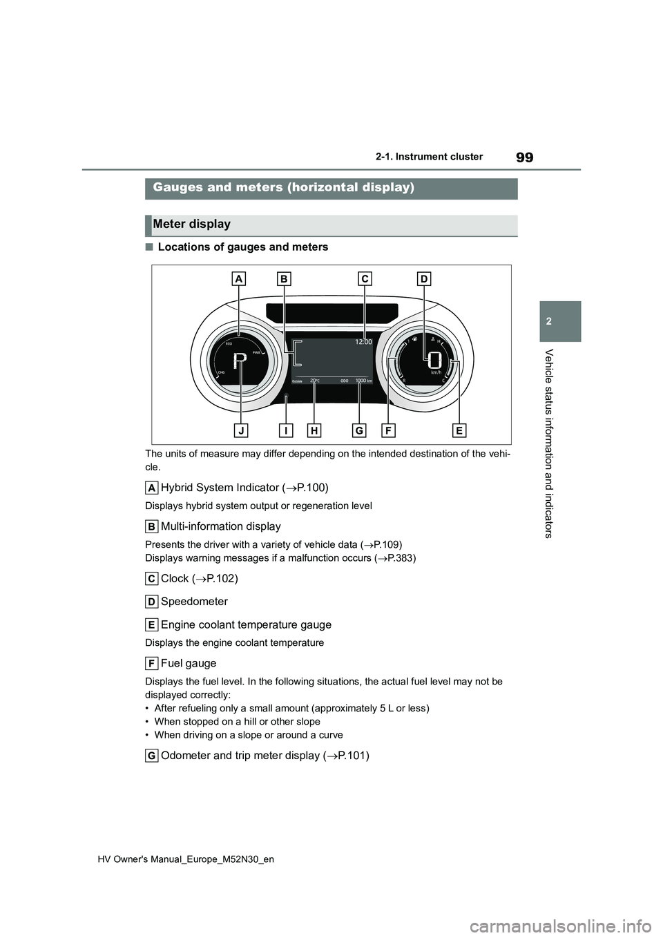
■Locations of gauges and meters
The units of measure may differ depending on the intended destination of the vehi-
cle.
Hybrid System Indicator ( P. 1 0 0 )
Displays hybrid system output or regeneration level
Multi-information display
Presents the driver with a variety of vehicle data (P.109)
Displays warning messages if a malfunction occurs ( P.383)
Clock (P.102)
Speedometer
Engine coolant temperature gauge
Displays the engine coolant temperature
Fuel gauge
Displays the fuel level. In the following situations, the actua l fuel level may not be
displayed correctly:
• After refueling only a small amount (approximately 5 L or less )
• When stopped on a hill or other slope
• When driving on a slope or around a curve
Odometer and trip meter display ( P.101)
Gauges and meters (horizontal display)
Meter display
Page 103 of 590
101
2
HV Owner's Manual_Europe_M52N30_en
2-1. Instrument cluster
Vehicle status information and indicators
■Fuel gauge and driving range dis-
play
The fuel gauge and driving range dis- play are linked. If the fuel gauge and
driving range display do not update after refueling a small amount, they can be updated by performing the following pro-
cedure:
1 Stop the vehicle on a level surface.
Wait until the fuel in the fuel tank stabi- lizes.
2 Press the display change button to
change the odometer and trip meter display to the odometer.
3 Turn the power switch off.
4 While pressing and holding the dis- play change button, turn the power
switch to ON.
5 Continue holding the display change button for approximately 5 seconds.
Release the button when the odometer
begins blinking.
Updating will be complete when the odometer blinks for approximately 5
seconds and then returns to the normal display.
■Liquid crystal display
P. 1 1 0
■Customization
The gauges and meters can be custom-
ized in of the multi-information dis-
play. ( P.431)
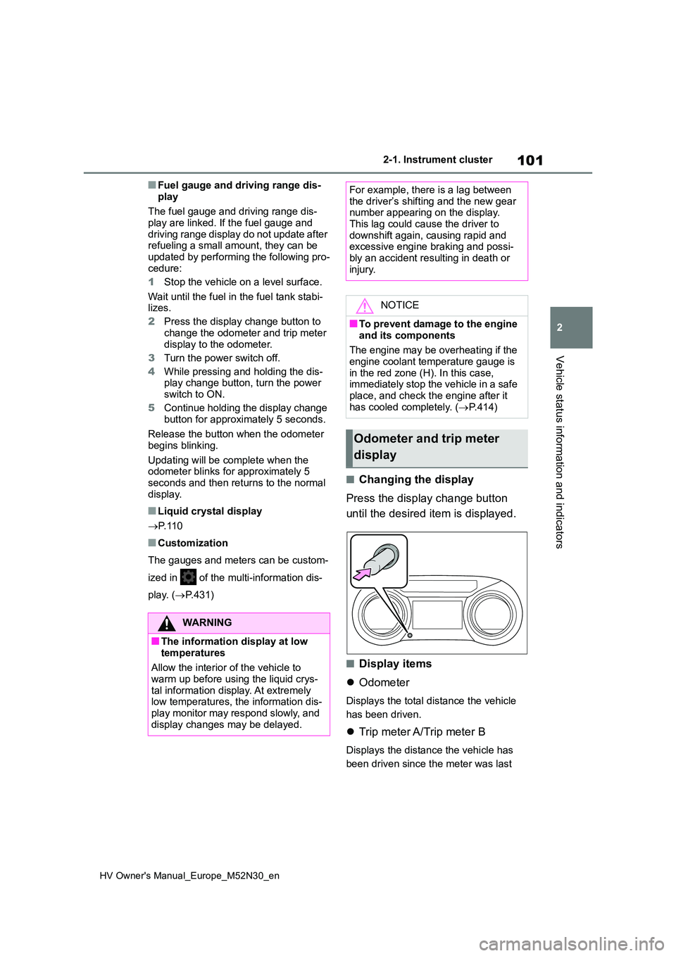
■Changing the display
Press the display change button
until the desired item is displayed.
■Display items
Odometer
Displays the total distance the vehicle
has been driven.
Trip meter A/Trip meter B
Displays the distance the vehicle has
been driven since the meter was last
WARNING
■The information display at low
temperatures
Allow the interior of the vehicle to warm up before using the liquid crys-
tal information display. At extremely low temperatures, the information dis-play monitor may respond slowly, and
display changes may be delayed.
For example, there is a lag between the driver’s shifting and the new gear number appearing on the display.
This lag could cause the driver to downshift again, causing rapid and excessive engine braking and possi-
bly an accident resulting in death or injury.
NOTICE
■To prevent damage to the engine
and its components
The engine may be overheating if the engine coolant temperature gauge is
in the red zone (H). In this case, immediately stop the vehicle in a safe place, and check the engine after it
has cooled completely. ( P.414)
Odometer and trip meter
display
Page 293 of 590
291
5
HV Owner's Manual_Europe_M52N30_en
5-1. Using the air conditioning system and defogger
Interior features
windshield effectively.
●If you turn “A/C” off, the windows may fog up more easily.
●The windows may fog up if the recir-culated air mode is used.
■When driving on dusty roads
Close all windows. If dust thrown up by the vehicle is still drawn into the vehicle after closing the windows, it is recom-
mended that the air intake mode be set to outside air mode and the fan speed to any setting except off.
■Outside/recirculated air mode
●Setting to the recirculated air mode temporarily is recommended in pre-
venting dirty air from entering the vehicle interior and helping to cool the vehicle when the outside air tempera-
ture is high.
●Outside/recirculated air mode may
automatically switch depending on the temperature setting or the inside tem-perature.
■Operation of the air conditioning
system in Eco drive mode
●In Eco drive mode, the air conditioning
system is controlled as follows to pri- oritize fuel efficiency:• Engine speed and compressor opera-
tion controlled to restrict heating/cool- ing capacity• Fan speed restricted when automatic
mode is selected
●To improve air conditioning perfor-
mance, perform the following opera- tions:• Adjust the fan speed
• Turn off Eco drive mode ( P.275)
●Even when the drive mode is set to
Eco drive mode, the air conditioning eco mode can be turned off by press-ing the “FAST/ECO” switch. ( P.290)
■When the outside temperature falls
to nearly 0°C (32°F)
The dehumidification function may not operate even when “A/C” switch is
pressed.
■Ventilation and air conditioning
odors
●To let fresh air in, set the air condition-
ing system to the outside air mode.
●During use, various odors from inside
and outside the vehicle may enter into and accumulate in the air conditioning system. This may then cause odor to
be emitted from the vents.
●To reduce potential odors from occur-
ring: • It is recommended that the air condi-tioning system be set to outside air
mode prior to turning the vehicle off. • The start timing of the blower may be delayed for a short period of time
immediately after the air conditioning system is started in automatic mode.
●When parking, the system automati-cally switches to outside air mode to encourage better air circulation
throughout the vehicle, helping to reduce odors that occur when starting the vehicle.
■Air conditioning filter
P. 3 4 6
■Customization
Some functions can be customized. ( P.431)
WARNING
■To prevent the windshield from fogging up
Do not use the windshield defogger
switch during cool air operation in extremely humid weather. The differ-ence between the temperature of the
outside air and that of the windshield can cause the outer surface of the windshield to fog up, blocking your
vision.
■When the outside rear view mir-
ror defoggers are operating
Do not touch the outside rear view mirror surfaces, as they can become
very hot and burn you.
Page 415 of 590
413
7
HV Owner's Manual_Europe_M52N30_en
7-2. Steps to take in an emergency
When trouble arises
WARNING
●Make sure each jumper cable is connected to the correct terminal
and that it is not unintentionally in contact with any other than the intended terminal.
●Do not allow the other end of the jumper cable connected to the “+”
terminal to come into contact with any other parts or metal surfaces in the area, such as brackets or
unpainted metal.
●Do not allow the + and - clamps of
the jumper cables to come into con- tact with each other.
●Do not smoke, use matches, ciga-rette lighters or allow open flame near the 12-volt battery.
■12-volt battery precautions
The 12-volt battery contains poison-
ous and corrosive acidic electrolyte, while related parts contain lead and lead compounds. Observe the follow-
ing precautions when handling the 12-volt battery:
●When working with the 12-volt bat-tery, always wear safety glasses and take care not to allow any bat-
tery fluids (acid) to come into con- tact with skin, clothing or the vehicle body.
●Do not lean over the 12-volt battery.
●In the event that battery fluid comes into contact with the skin or eyes, immediately wash the affected area
with water and seek medical atten- tion. Place a wet sponge or cloth over the affected area until medical
attention can be received.
●Always wash your hands after han-
dling the 12-volt battery support, terminals, and other battery-related parts.
●Do not allow children near the 12-volt battery.
■After recharging the 12-volt bat-tery
Have the 12-volt battery inspected at
any authorized Toyota retailer or Toyota authorized repairer, or any reli-able repairer as soon as possible.
If the 12-volt battery is deteriorating, continued use may cause the 12-volt battery to emit a malodorous gas,
which may be detrimental to the health of passengers.
■When replacing the 12-volt bat-tery
●For information regarding 12-volt
battery replacement, contact any authorized Toyota retailer or Toyota authorized repairer, or any reliable
repairer.
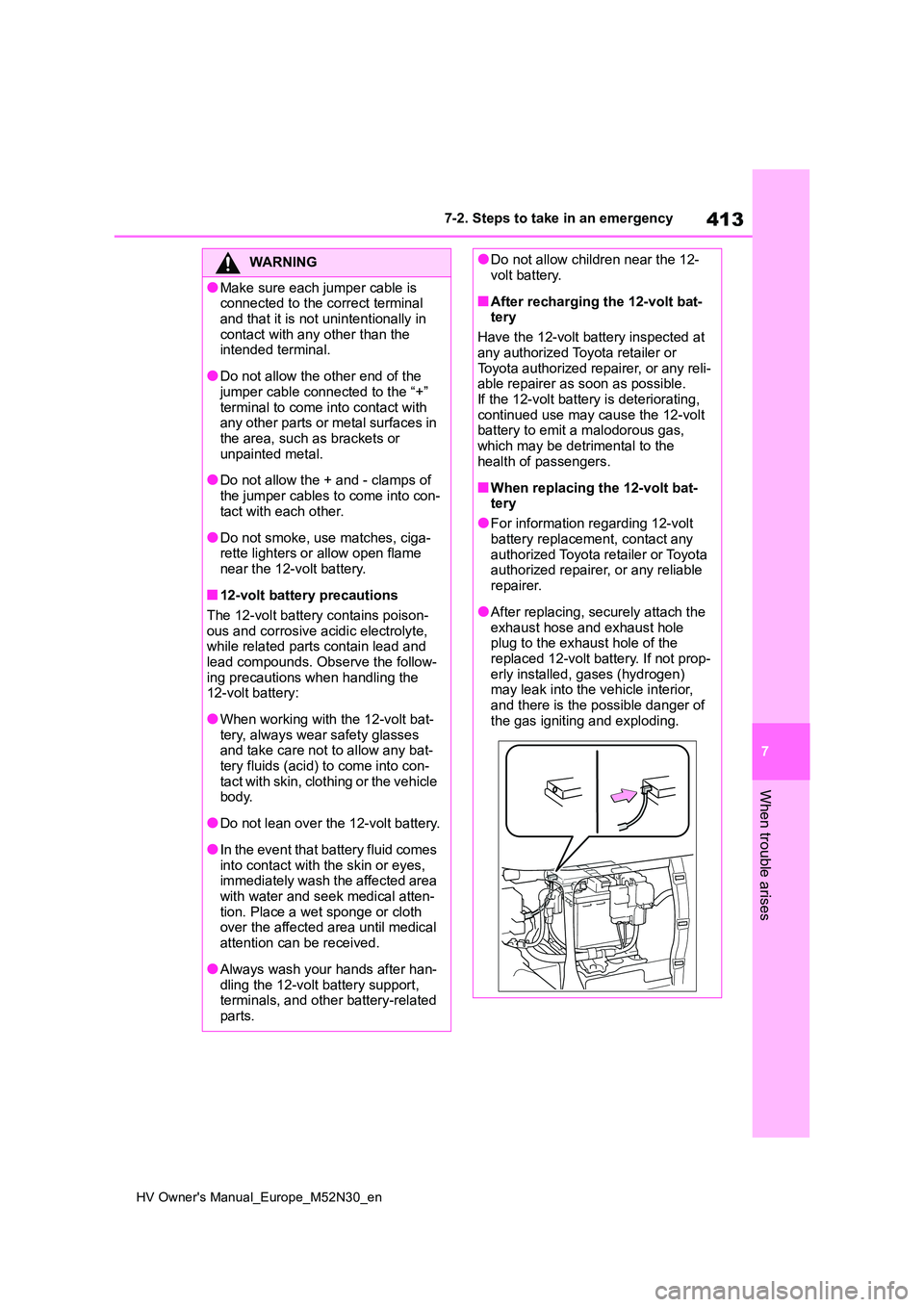
●After replacing, securely attach the
exhaust hose and exhaust hole plug to the exhaust hole of the replaced 12-volt battery. If not prop-
erly installed, gases (hydrogen) may leak into the vehicle interior, and there is the possible danger of
the gas igniting and exploding.
Page 584 of 590
582
HV Owner's Manual_Europe_M52N30_en
Alphabetical Index
N
Navigation system-linked display
..................................... 107, 112, 116
O
Odometer ................................ 96, 101
Odometer and trip meter display
Display change button ......... 96, 101
Display items........................ 97, 101
Oil
Engine oil ................................... 423
Opener
Back door ................................... 139
Fuel filler door ............................ 202
Hood .......................................... 322
Outside rear view mirrors
Adjustment ................................. 153
BSM (Blind Spot Monitor) .......... 248
Folding ....................................... 154
Outside rear view mirror defoggers
................................................. 290
RCTA (Rear Crossing Traffic Alert)
................................................. 260
Outside temperature ........ 94, 99, 119
Overheating .................................. 414
P
Panoramic roof shade .................. 309
Parking assist sensors (Toyota park-
ing assist-sensor) ...................... 253
Parking brake ................................ 184
Operation ................................... 184
Parking brake engaged warning
buzzer ...................................... 186
Warning light .............................. 380
Warning message ...................... 186
Parking Support Brake (PKSB) ... 265
Enabling/disabling the Parking Sup-
port Brake ................................ 266
Parking Support Brake function
(rear-crossing vehicles)............273
Parking Support Brake function
(static objects) .......................... 270
Warning lights.............................379
Warning message ...................... 269
PCS (Pre-Collision System) ......... 209
Enabling/disabling the pre-collision
system...................................... 212
Function ..................................... 209
Warning light .............................. 380
Personal lights .............................. 295
Wattage ...................................... 428
PKSB (Parking Support Brake) ... 265
Enabling/disabling the Parking Sup-
port Brake ................................ 266
Parking Support Brake function
(rear-crossing vehicles)............273
Parking Support Brake function
(static objects) .......................... 270
Warning lights.............................379
Warning message ...................... 269
Power control unit .......................... 79
Power control unit coolant .......... 327
Capacity ..................................... 425
Checking .................................... 327
Preparing and checking before win-
ter ............................................. 284
Power mode .................................. 275
Power outlet .................................. 303
Power steering (Electric power
steering system) ......................... 277
Warning light .............................. 377
Power switch ......................... 173, 175
Auto power off function .............. 178
Changing the power switch modes
......................................... 174, 177