turn signal TOYOTA YARIS CROSS 2022 Owner's Manual
[x] Cancel search | Manufacturer: TOYOTA, Model Year: 2022, Model line: YARIS CROSS, Model: TOYOTA YARIS CROSS 2022Pages: 618, PDF Size: 130.77 MB
Page 303 of 618
301
4
CV Owner's Manual_Europe_M52N20_en
4-5. Using the driving support systems
Driving
■ABS (Anti-lock Brake System)
Helps to prevent wheel lock when
the brakes are applied suddenly, or
if the brakes are applied while driv-
ing on a slippery road surface
■Brake assist
Generates an increased level of
braking force after the brake pedal
is depressed when the system
detects a panic stop situation
■VSC (Vehicle Stability Control)
Helps the driver to control skidding
when swerving suddenly or turning
on slippery road surfaces.
■Trailer Sway Control
Helps the driver to control trailer
sway by selectively applying brake
pressure for individual wheels and
reducing driving torque when trailer
sway is detected.
■TRC (Traction Control)
Helps to maintain drive power and
prevent the drive wheels from spin-
ning when starting the vehicle or
accelerating on slippery roads
■Active Cornering Assist (ACA)
Helps to prevent the vehicle from
drifting to the outer side by perform-
ing inner wheel brake control when
attempting to accelerate while turn-
ing
■Hill-start assist control
Helps to reduce the backward
movement of the vehicle when
starting on an uphill
■EPS (Electric Power Steering)
Employs an electric motor to
reduce the amount of effort needed
to turn the steering wheel.
■Emergency brake signal
When the brakes are applied sud-
denly, the emergency flashers auto-
matically flash to alert the vehicle
behind.
■The Secondary Collision
Brake
When the SRS airbag sensor
detects a collision and the system
operates, the brakes and brake
lights are automatically controlled
to reduce the vehicle speed and
help reduce the possibility of further
damage due to a secondary colli-
sion.
Driving assist systems
To keep driving safety and per-
formance, the f ollowing sys-
tems operate automatically in
response to various driving sit-
uations. Be aware, however,
that these systems are supple-
mentary and should not be
relied upon too heavily when
operating the vehicle.
Summary of the driving
assist systems
Page 306 of 618
304
CV Owner's Manual_Europe_M52N20_en
4-5. Using the driving support systems
■Operating conditions of emergency
brake signal
When the following conditions are met, the emergency brake signal will oper-
ates:
●The emergency flashers are off
●Actual vehicle speed is over 55 km/h (35 mph)
●The system judges from the vehicle deceleration that it is a sudden brak-
ing operation.
■Automatic system cancelation of emergency brake signal
The emergency brake signal will be can-
celed in any of the following situations:
●The emergency flashers are turned
on.
●The system judges from the vehicle
deceleration that is not a sudden brak- ing operation.
■Secondary Collision Brake operat-ing conditions
The system operates when the SRS air- bag sensor detects a collision while the vehicle is in motion.
However, the system does not operate when components are damaged.
■Secondary Collision Brake auto-matic cancelation
The system is automatically canceled in any of the following situations.
●The vehicle speed drops approxi-mately 0 km/h (0 mph)
●A certain amount of time elapses during operation
●The accelerator pedal is depressed a large amount
WARNING
■The ABS does not operate effec-
tively when
●The limits of tire gripping perfor- mance have been exceeded (such
as excessively worn tires on a snow covered road).
●The vehicle hydroplanes while driv-ing at high speed on wet or slick roads.
■Stopping distance when the ABS is operating may exceed that of
normal conditions
The ABS is not designed to shorten the vehicle’s stopping distance.
Always maintain a safe distance from the vehicle in front of you, especially in the following situations:
●When driving on dirt, gravel or snow-covered roads
●When driving with tire chains
●When driving over bumps in the road
●When driving over roads with pot-holes or uneven surfaces
■TRC/VSC may not operate effec-tively when
Directional control and power may not
be achievable while driving on slip- pery road surfaces, even if the TRC/VSC system is operating. Drive
the vehicle carefully in conditions where stability and power may be lost.
■Active Cornering Assist does not operate effectively when
●Do not overly rely on Active Corner-ing Assist. Active Cornering Assist may not operate effectively when
accelerating down slopes or driving on slippery road surfaces.
●When Active Cornering Assist fre-quently operates, Active Cornering Assist may temporarily stop operat-
ing to ensure proper operation of the brakes, TRC and VSC.
Page 368 of 618
366
CV Owner's Manual_Europe_M52N20_en
6-3. Do-it-yourself maintenance
■Routine tire inflation pressure checks
The tire pressure warning system does not replace routine tire inflation pressure checks. Make sure to check tire inflation
pressure as part of your routine of daily vehicle checks.
■Tire inflation pressure
●It may take a few minutes to display the tire inflation pressure after the engine switch is turned to ON. It may
also take a few minutes to display the tire inflation pressure after inflation pressure has been adjusted.
●Tire inflation pressure changes with temperature. The displayed values
may also be different from the values measured using a tire pressure gauge.
■Situations in which the tire pres-
sure warning system may not oper- ate properly
●In the following cases, the tire pres-sure warning system may not operate properly.
• If non-genuine Toyota wheels are used.• A tire has been replaced with a tire
that is not an OE (Original Equipment) tire.• A tire has been replaced with a tire
that is not of the specified size. • Tire chains, etc. are equipped.
• An auxiliary-supported run-flat tire is equipped.• If a window tint that affects the radio
wave signals is installed. • If there is a lot of snow or ice on the vehicle, particularly around the wheels
or wheel housings. • If the tire inflation pressure is extremely higher than the specified
level. • If tires not equipped with tire pressure warning valves and transmitters are
used. • If the ID code on the tire pressure warning valves and transmitters is not
registered in the tire pressure warning
computer.
●Performance may be affected in the following situations.
• Near a TV tower, electric power plant, gas station, radio station, large dis-play, airport or other facility that gen-
erates strong radio waves or electrical noise.• When carrying a portable radio, cellu-
lar phone, cordless phone or other wireless communication device.
●When the vehicle is parked, the time taken for the warning to start or go off could be extended.
●When tire inflation pressure declines rapidly for example when a tire has
burst, the not to able detect.
■Warning performance of the tire pressure warning system
The warning of the tire pressure warning
system will change in accordance with driving conditions. For this reason, the system may give a warning even if the
tire pressure does not reach a low enough level, or if the pressure is higher than the pressure that was adjusted to
when the system was initialized.
When replacing tires or wheels, tire
pressure warning valves and trans-
mitters must also be installed.
When new tire pressure warning
valves and transmitters are
installed, new ID codes must be
registered in the tire pressure warn-
ing computer and the tire pressure
warning system must be initialized.
Have tire pressure warning valves
and transmitter ID codes regis-
tered any authorized Toyota retailer
or Toyota authorized repairer, or
Installing tire pressure warn-
ing valves and transmitters
Page 388 of 618
386
CV Owner's Manual_Europe_M52N20_en
6-3. Do-it-yourself maintenance
Check the wattage of the light bulb
to be replaced. ( P.455)
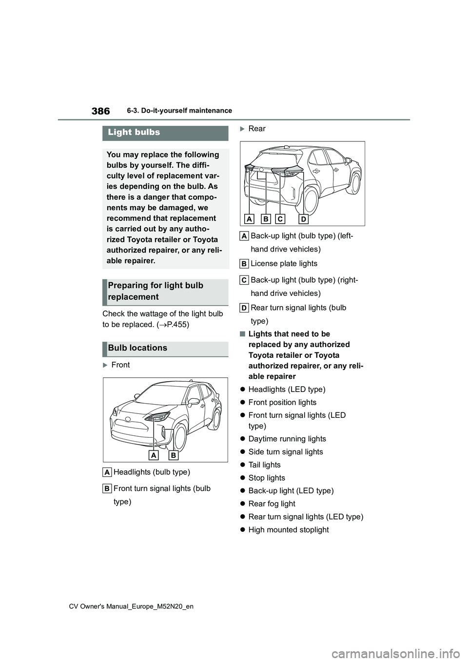
Front
Headlights (bulb type)
Front turn signal lights (bulb
type)
Rear
Back-up light (bulb type) (left-
hand drive vehicles)
License plate lights
Back-up light (bulb type) (right-
hand drive vehicles)
Rear turn signal lights (bulb
type)
■Lights that need to be
replaced by any authorized
Toyota retailer or Toyota
authorized repairer, or any reli-
able repairer
Headlights (LED type)
Front position lights
Front turn signal lights (LED
type)
Daytime running lights
Side turn signal lights
Ta i l l i g h t s
Stop lights
Back-up light (LED type)
Rear fog light
Rear turn signal lights (LED type)
High mounted stoplight
Light bulbs
You may replace the following
bulbs by yourself. The diffi-
culty level of replacement var-
ies depending on the bulb. As
there is a danger that compo-
nents may be damaged, we
recommend that replacement
is carried out by any autho-
rized Toyota retailer or Toyota
authorized repairer, or any reli-
able repairer.
Preparing for light bulb
replacement
Bulb locations
Page 389 of 618
387
6
CV Owner's Manual_Europe_M52N20_en
6-3. Do-it-yourself maintenance
Maintenance and care
■LED light bulbs
The lights other than the following lights
each consist of a number of LEDs. If any of the LEDs burn out, take your vehicle to any authorized Toyota retailer or
Toyota authorized repairer, or any reli- able repairer to have the light replaced.
●Headlights (bulb type)
●Front turn signal lights (bulb type)
●Rear turn signal lights (bulb type)
●License plate lights
●Back-up light (bulb type)
■Condensation build-up on the
inside of the lens
Temporary condensation build-up on the inside of the headlight lens does not
indicate a malfunction. Contact any authorized Toyota retailer or Toyota authorized repairer, or any reliable
repairer for more information in the fol- lowing situations:
●Large drops of water have built up on the inside of the lens.
●Water has built up inside the head-light.
■When replacing light bulbs
P. 3 8 4
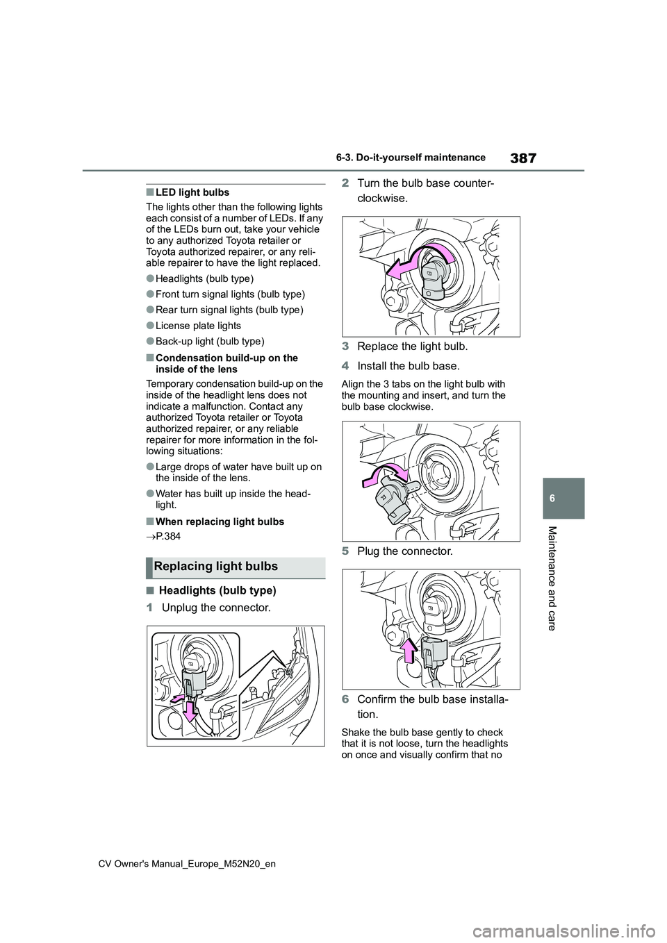
■Headlights (bulb type)
1 Unplug the connector.
2 Turn the bulb base counter-
clockwise.
3 Replace the light bulb.
4 Install the bulb base.
Align the 3 tabs on the light bulb with the mounting and insert, and turn the
bulb base clockwise.
5 Plug the connector.
6 Confirm the bulb base installa-
tion.
Shake the bulb base gently to check that it is not loose, turn the headlights
on once and visually confirm that no
Replacing light bulbs
Page 390 of 618
388
CV Owner's Manual_Europe_M52N20_en
6-3. Do-it-yourself maintenance
light is leaking through the mounting.
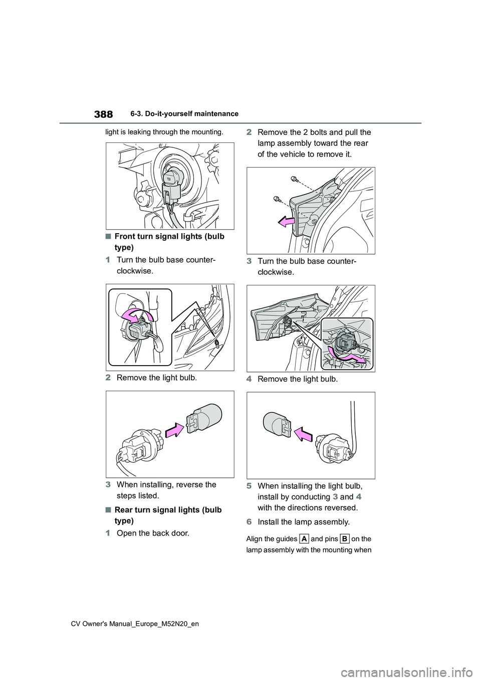
■Front turn signal lights (bulb
type)
1 Turn the bulb base counter-
clockwise.
2 Remove the light bulb.
3 When installing, reverse the
steps listed.
■Rear turn signal lights (bulb
type)
1 Open the back door.
2 Remove the 2 bolts and pull the
lamp assembly toward the rear
of the vehicle to remove it.
3 Turn the bulb base counter-
clockwise.
4 Remove the light bulb.
5 When installing the light bulb,
install by conducting 3 and 4
with the directions reversed.
6 Install the lamp assembly.
Align the guides and pins on the
lamp assembly with the mounting when
Page 396 of 618
394
CV Owner's Manual_Europe_M52N20_en
7-1. Essential information
7-1.Esse ntial informa tion
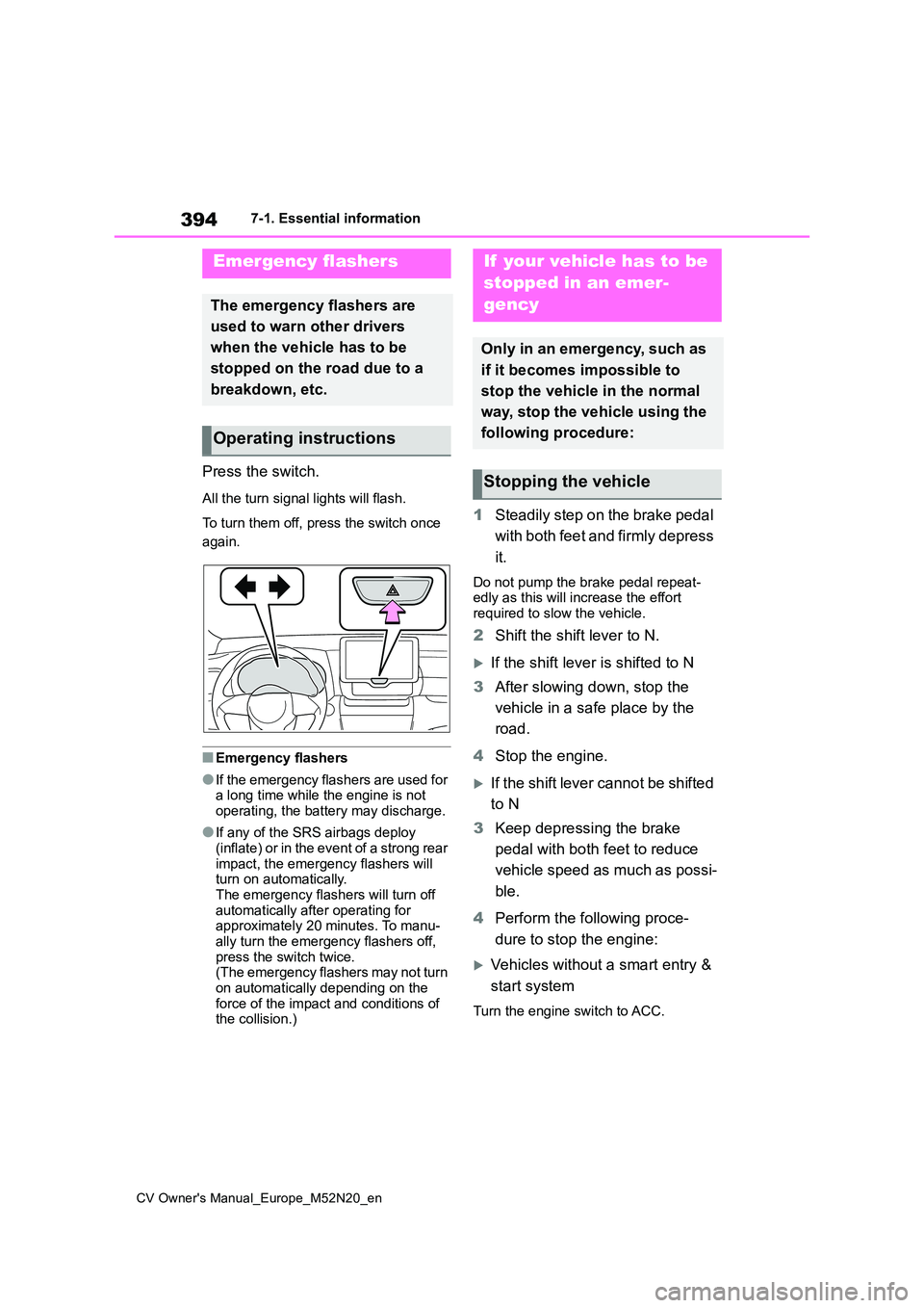
Press the switch.
All the turn signal lights will flash.
To turn them off, press the switch once
again.
■Emergency flashers
●If the emergency flashers are used for a long time while the engine is not
operating, the battery may discharge.
●If any of the SRS airbags deploy
(inflate) or in the event of a strong rear impact, the emergency flashers will turn on automatically.
The emergency flashers will turn off automatically after operating for approximately 20 minutes. To manu-
ally turn the emergency flashers off, press the switch twice.(The emergency flashers may not turn
on automatically depending on the force of the impact and conditions of the collision.)
1 Steadily step on the brake pedal
with both feet and firmly depress
it.
Do not pump the brake pedal repeat- edly as this will increase the effort required to slow the vehicle.
2 Shift the shift lever to N.
If the shift lever is shifted to N
3 After slowing down, stop the
vehicle in a safe place by the
road.
4 Stop the engine.
If the shift lever cannot be shifted
to N
3 Keep depressing the brake
pedal with both feet to reduce
vehicle speed as much as possi-
ble.
4 Perform the following proce-
dure to stop the engine:
Vehicles without a smart entry &
start system
Turn the engine switch to ACC.
Emergency flashers
The emergency flashers are
used to warn other drivers
when the vehicle has to be
stopped on the road due to a
breakdown, etc.
Operating instructions
If your vehicle has to be
stopped in an emer-
gency
Only in an emergency, such as
if it becomes impossible to
stop the vehicle in the normal
way, stop the vehicle using the
following procedure:
Stopping the vehicle
Page 457 of 618
455
8
CV Owner's Manual_Europe_M52N20_en
8-1. Specifications
Vehicle specifications
18-inch tires
Compact spare tire (if equipped)
*: If equipped
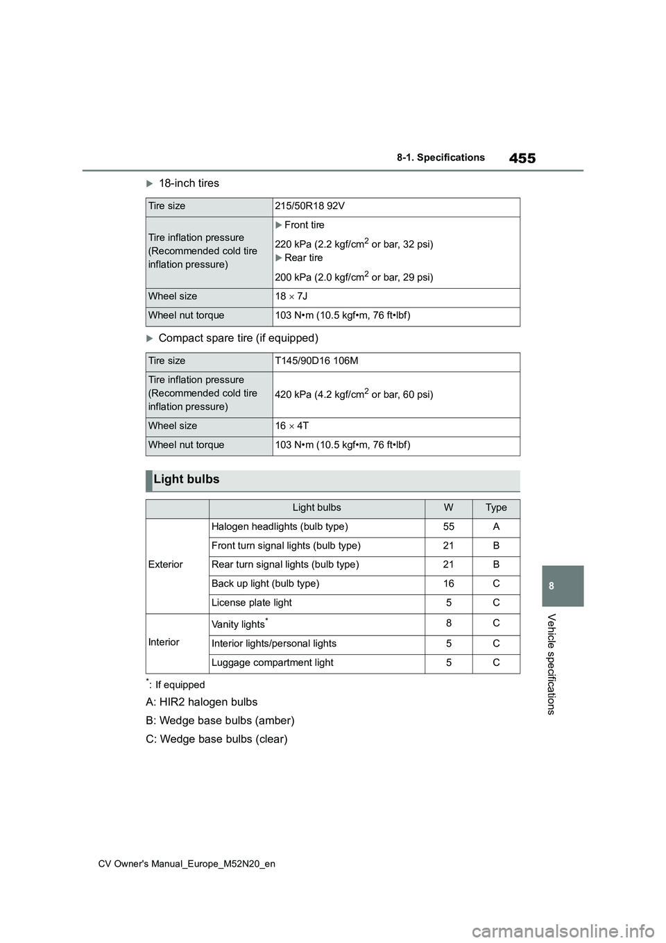
A: HIR2 halogen bulbs
B: Wedge base bulbs (amber)
C: Wedge base bulbs (clear)
Tire size215/50R18 92V
Tire inflation pressure
(Recommended cold tire
inflation pressure)
Front tire
220 kPa (2.2 kgf/cm2 or bar, 32 psi)
Rear tire
200 kPa (2.0 kgf/cm2 or bar, 29 psi)
Wheel size18 7J
Wheel nut torque103 N•m (10.5 kgf•m, 76 ft•lbf)
Tire sizeT145/90D16 106M
Tire inflation pressure
(Recommended cold tire
inflation pressure)
420 kPa (4.2 kgf/cm2 or bar, 60 psi)
Wheel size16 4T
Wheel nut torque103 N•m (10.5 kgf•m, 76 ft•lbf)
Light bulbs
Light bulbsWTyp e
Exterior
Halogen headlights (bulb type)55A
Front turn signal lights (bulb type)21B
Rear turn signal lights (bulb type)21B
Back up light (bulb type)16C
License plate light5C
Interior
Vanity lights*8C
Interior lights/personal lights5C
Luggage compartment light5C
Page 463 of 618
461
8
CV Owner's Manual_Europe_M52N20_en
8-2. Customization
Vehicle specifications
*: If equipped
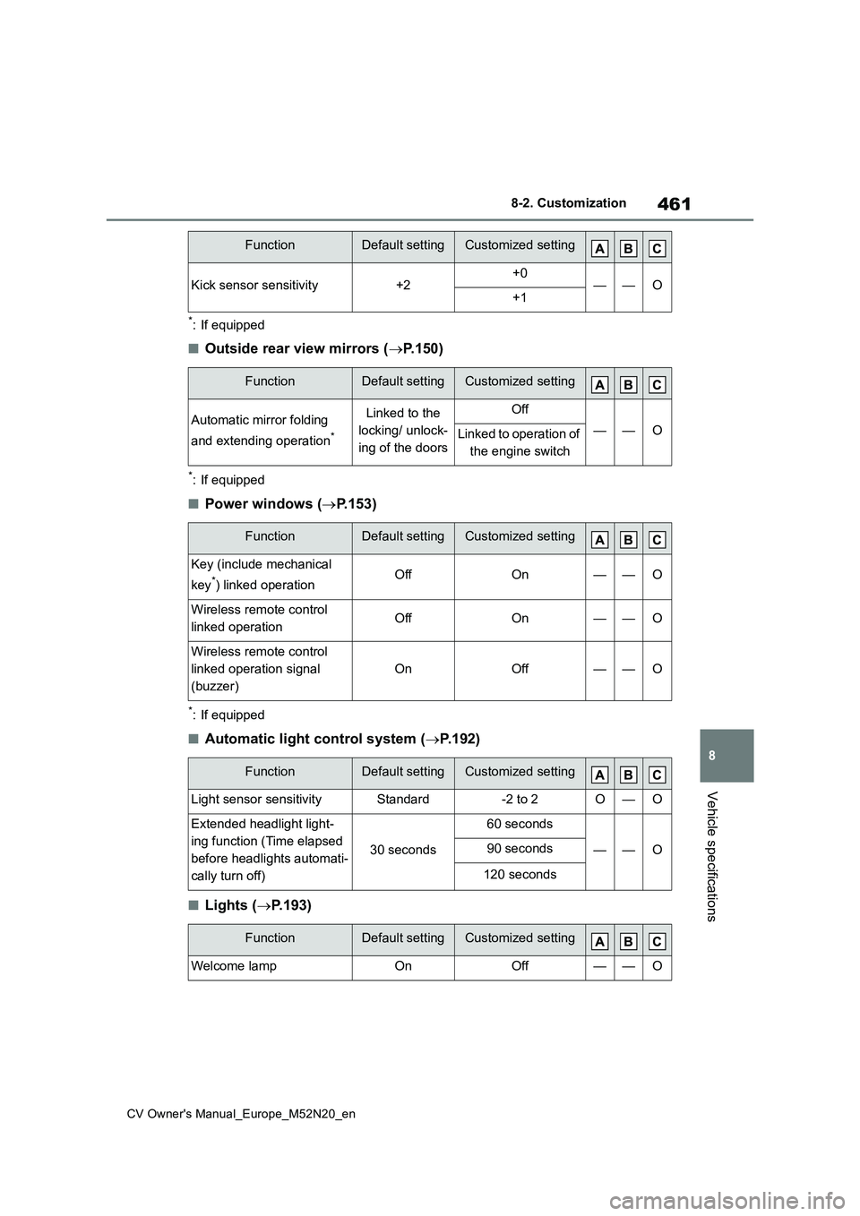
■Outside rear view mirrors (P.150)
*: If equipped
■Power windows (P.153)
*: If equipped
■Automatic light control system (P.192)
■Lights (P.193)
Kick sensor sensitivity+2+0——O+1
FunctionDefault settingCustomized setting
Automatic mirror folding
and extending operation*
Linked to the
locking/ unlock-
ing of the doors
Off
——OLinked to operation of
the engine switch
FunctionDefault settingCustomized setting
Key (include mechanical
key*) linked operationOffOn——O
Wireless remote control
linked operationOffOn——O
Wireless remote control
linked operation signal
(buzzer)
OnOff——O
FunctionDefault settingCustomized setting
Light sensor sensitivityStandard-2 to 2O—O
Extended headlight light-
ing function (Time elapsed
before headlights automati-
cally turn off)
30 seconds
60 seconds
——O90 seconds
120 seconds
FunctionDefault settingCustomized setting
Welcome lampOnOff——O
FunctionDefault settingCustomized setting
Page 477 of 618
475
CV Owner's Manual_Europe_M52N20_en
Alphabetical Index
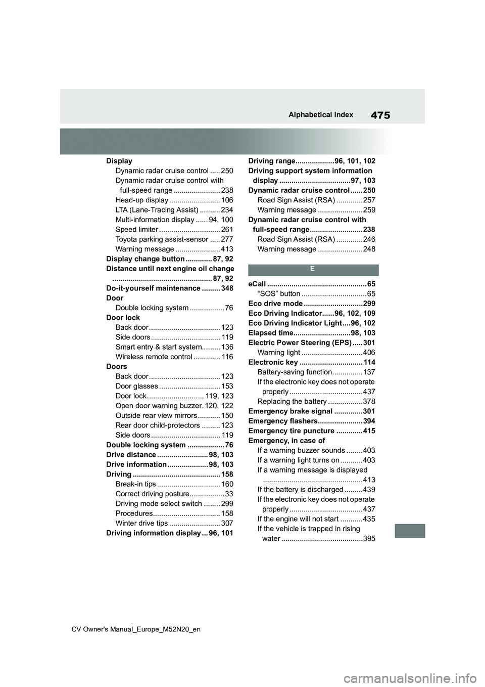
Display
Dynamic radar cruise control ..... 250
Dynamic radar cruise control with
full-speed range ....................... 238
Head-up display ......................... 106
LTA (Lane-Tracing Assist) .......... 234
Multi-information display ...... 94, 100
Speed limiter .............................. 261
Toyota parking assist-sensor ..... 277
Warning message ...................... 413
Display change button ............. 87, 92
Distance until next engine oil change
................................................. 87, 92
Do-it-yourself maintenance ......... 348
Door
Double locking system ................. 76
Door lock
Back door ................................... 123
Side doors .................................. 119
Smart entry & start system......... 136
Wireless remote control ............. 116
Doors
Back door ................................... 123
Door glasses .............................. 153
Door lock ............................ 119, 123
Open door warning buzzer. 120, 122
Outside rear view mirrors ........... 150
Rear door child-protectors ......... 123
Side doors .................................. 119
Double locking system .................. 76
Drive distance ......................... 98, 103
Drive information .................... 98, 103
Driving ........................................... 158
Break-in tips ............................... 160
Correct driving posture................. 33
Driving mode select switch ........ 299
Procedures................................. 158
Winter drive tips ......................... 307
Driving information display ... 96, 101
Driving range................... 96, 101, 102
Driving support system information
display ...................................97, 103
Dynamic radar cruise control ...... 250
Road Sign Assist (RSA) ............. 257
Warning message ...................... 259
Dynamic radar cruise control with
full-speed range.......................... 238
Road Sign Assist (RSA) ............. 246
Warning message ...................... 248
E
eCall ................................................. 65
“SOS” button ................................ 65
Eco drive mode .............................299
Eco Driving Indicator...... 96, 102, 109
Eco Driving Indicator Light ....96, 102
Elapsed time............................98, 103
Electric Power Steering (EPS) ..... 301
Warning light .............................. 406
Electronic key ............................... 114
Battery-saving function............... 137
If the electronic key does not operate
properly .................................... 437
Replacing the battery ................. 378
Emergency brake signal .............. 301
Emergency flashers...................... 394
Emergency tire puncture ............. 415
Emergency, in case of
If a warning buzzer sounds ........ 403
If a warning light turns on ........... 403
If a warning message is displayed
................................................. 413
If the battery is discharged ......... 439
If the electronic key does not operate
properly .................................... 437
If the engine will not start ........... 435
If the vehicle is trapped in rising
water ........................................395