TOYOTA YARIS LIFTBACK 2020 Owners Manual (in English)
Manufacturer: TOYOTA, Model Year: 2020, Model line: YARIS LIFTBACK, Model: TOYOTA YARIS LIFTBACK 2020Pages: 520, PDF Size: 8.71 MB
Page 201 of 520
2014-6. Using the driving support systems
4
Driving
Cruise control∗
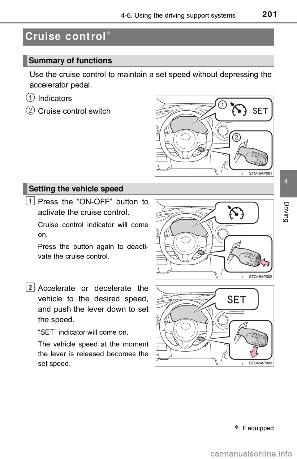
Use the cruise control to maintain a set speed without depressing the
accelerator pedal. Indicators
Cruise control switch
Press the “ON-OFF” button to
activate the cruise control.
Cruise control indicator will come
on.
Press the button again to deacti-
vate the cruise control.
Accelerate or decelerate the
vehicle to the desired speed,
and push the lever down to set
the speed.
“SET” indicator will come on.
The vehicle speed at the moment
the lever is released becomes the
set speed.
∗: If equipped
Summary of functions
1
2
Setting the vehicle speed
1
2
Page 202 of 520
2024-6. Using the driving support systems
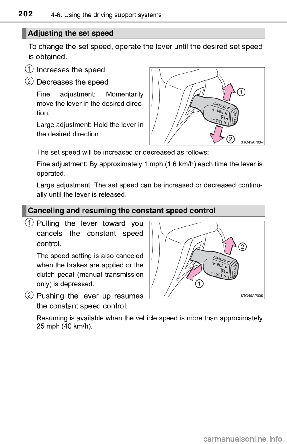
To change the set speed, operate the lever until the desired set speed
is obtained.
Increases the speed
Decreases the speed
Fine adjustment: Momentarily
move the lever in the desired direc-
tion.
Large adjustment: Hold the lever in
the desired direction.
The set speed will be increased or decreased as follows:
Fine adjustment: By approximately 1 mph (1.6 km/h) each time the lever is
operated.
Large adjustment: The set speed can be increased or decreased continu-
ally until the lever is released.
Pulling the lever toward you
cancels the c onstant speed
control.
The speed setting is also canceled
when the brakes are applied or the
clutch pedal (manual transmission
only) is depressed.
Pushing the lever up resumes
the constant speed control.
Resuming is available when the vehicle speed is more than approximately
25 mph (40 km/h).
Adjusting the set speed
1
2
Canceling and resuming the constant speed control
1
2
Page 203 of 520

2034-6. Using the driving support systems
4
Driving
■Cruise control can be set when
●The shift lever is in the D or range 3. (vehicles with an automatic transmis-
sion)
● Vehicle speed is above approximately 25 mph (40 km/h).
■ Accelerating after setting the vehicle speed
●The vehicle can be accelerated normally. After acceleration, the set speed
resumes.
● Even without canceling the cruise control, the set speed can be increased
by first accelerating the vehicle to the desired speed and then pushing the
lever down to set the new speed.
■ Automatic cruise co ntrol cancelation
Cruise control will stop maintaining the vehicle speed in any of the following
situations.
● Actual vehicle speed falls more than approximately 10 mph (16 km/h) below
the preset vehicle speed.
At this time, the memorized set speed is not retained.
● Actual vehicle speed is below approximately 25 mph (40 km/h).
● VSC is activated.
■ If the cruise control indicator comes on in yellow
Press the “ON-OFF” button once to deactivate the system, and then press
the button again to reactivate the system.
If the cruise control speed cannot be set or if the cruise control cancels imme-
diately after being activated, there may be a malfunction in the cruise control
system. Have the vehicle inspected by your Toyota dealer.
Page 204 of 520

2044-6. Using the driving support systems
WARNING
■To avoid operating the cruise control by mistake
Switch the cruise control off using the “ON-OFF” button when not in use.
■ Situations unsuitable for cruise control
Do not use cruise control in any of the following situations.
Doing so may result in loss of control and could cause an accident resulting
in death or serious injury.
● In heavy traffic
● On roads with sharp bends
● On winding roads
● On slippery roads, such as those covered with rain, ice or snow
● On steep hills
Vehicle speed may exceed the set speed when driving down a steep hill.
● During emergency towing
Page 205 of 520
2054-6. Using the driving support systems
4
Driving
Rear view monitor system
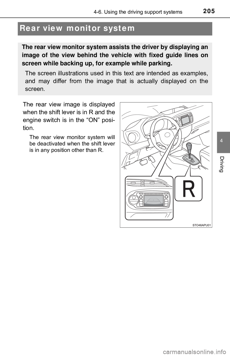
The rear view image is displayed
when the shift lever is in R and the
engine switch is in the “ON” posi-
tion.
The rear view monitor system will
be deactivated when the shift lever
is in any position other than R.
The rear view monitor system assists the driver by displaying an
image of the view behind the vehicle with fixed guide lines on
screen while backing up, for example while parking.
The screen illustrations used in this text are intended as examples,
and may differ from the image that is actually displayed on the
screen.
Page 206 of 520

2064-6. Using the driving support systems
■Screen description
The rear view monitor system scr een will be displayed if the shift
lever is shifted to R while the engin e switch is in the “ON” position.
Vehicle width guide lines
The line indicates a guide path when the vehicle is being backed straight
up.
The displayed width is wider than the actual vehicle width.
Vehicle center guide line
This line indicates the estimated vehicle center on the ground.
Distance guide line
The line shows distance behind the vehicle, a point approximately 1.5 ft.
(0.5 m) (red) from the edge of the bumper.
Distance guide line
The line shows distance behind the vehicle, a point approximately 3 ft.
(1 m) (blue) from the edge of the bumper.
Using the rear view monitor system
1
2
3
4
Page 207 of 520
2074-6. Using the driving support systems
4
Driving
■Area displayed on screen
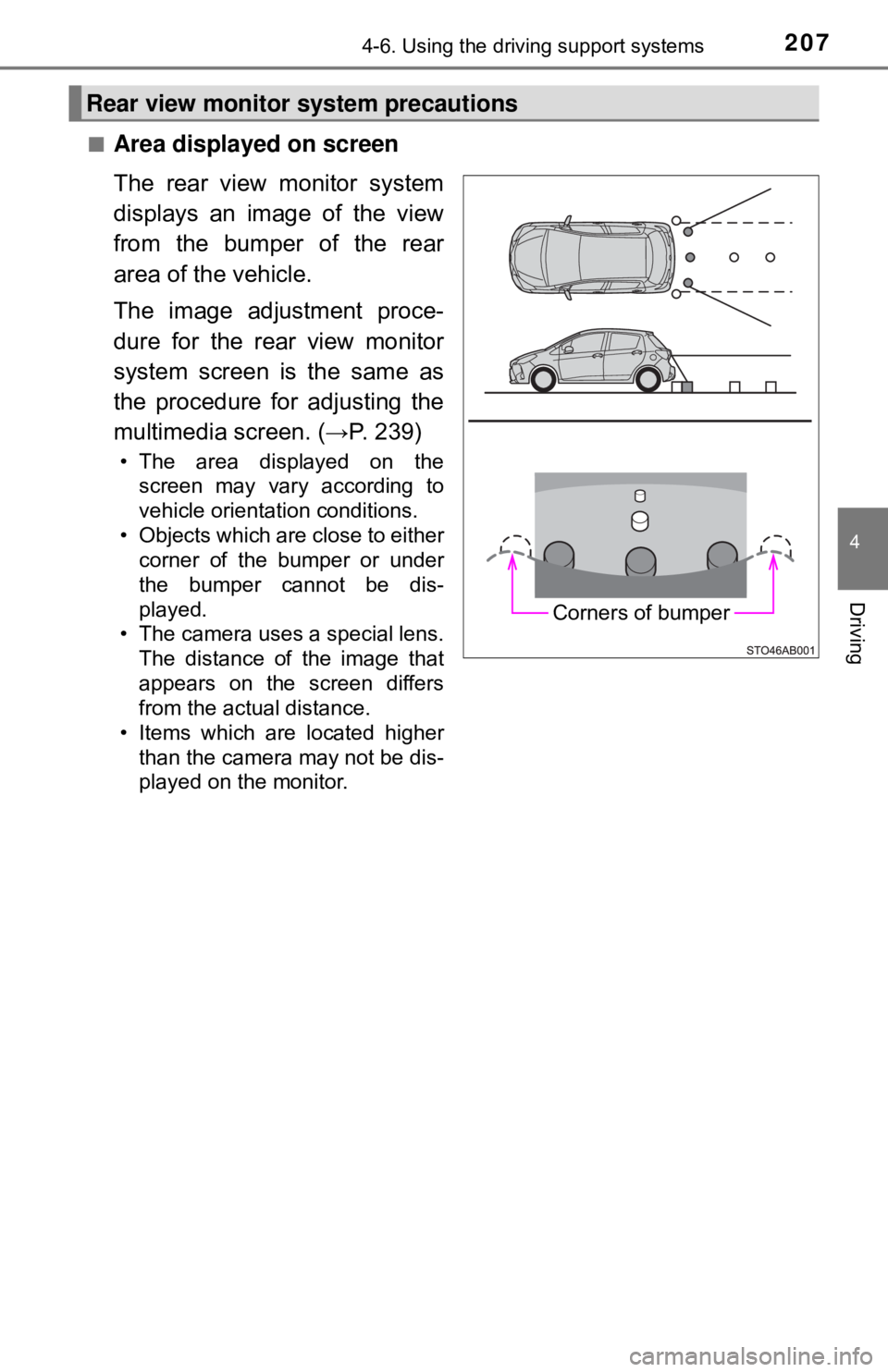
The rear view monitor system
displays an image of the view
from the bumper of the rear
area of the vehicle.
The image adjustment proce-
dure for the rear view monitor
system screen is the same as
the procedure for adjusting the
multimedia screen. (→P. 239)
• The area displayed on thescreen may vary according to
vehicle orientation conditions.
• Objects which are close to either corner of the bumper or under
the bumper cannot be dis-
played.
• The camera uses a special lens. The distance of the image that
appears on the screen differs
from the actual distance.
• Items which are located higher
than the camera may not be dis-
played on the monitor.
Rear view monitor system precautions
Corners of bumper
Page 208 of 520
2084-6. Using the driving support systems
■Rear view monitor system camera
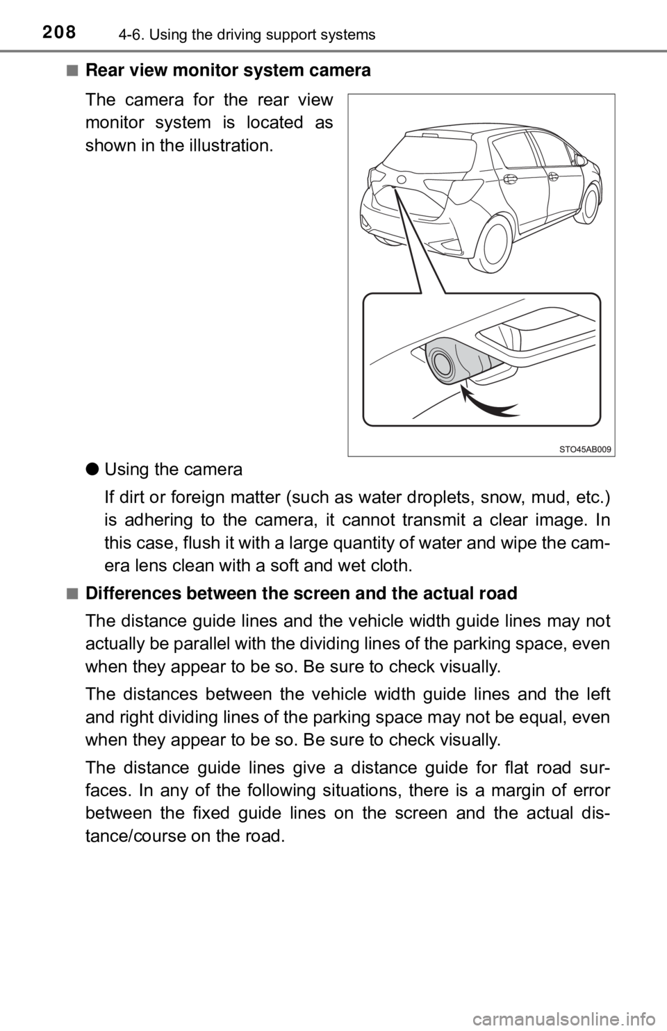
The camera for the rear view
monitor system is located as
shown in the illustration.
● Using the camera
If dirt or foreign matter (such as water droplets, snow, mud, etc.)
is adhering to the camera, it cannot transmit a clear image. In
this case, flush it with a large quantity of water and wipe the cam-
era lens clean with a soft and wet cloth.
■Differences between the screen and the actual road
The distance guide lines and the v ehicle width guide lines may not
actually be parallel with the dividi ng lines of the parking space, even
when they appear to be so. Be sure to check visually.
The distances between the vehicle width guide lines and the left
and right dividing lines of the parking space may not be equal, even
when they appear to be so. Be sure to check visually.
The distance guide lines give a distance guide for flat road sur-
faces. In any of the following situations, there is a margin of error
between the fixed guide lines on the screen and the actual dis-
tance/course on the road.
Page 209 of 520
2094-6. Using the driving support systems
4
Driving
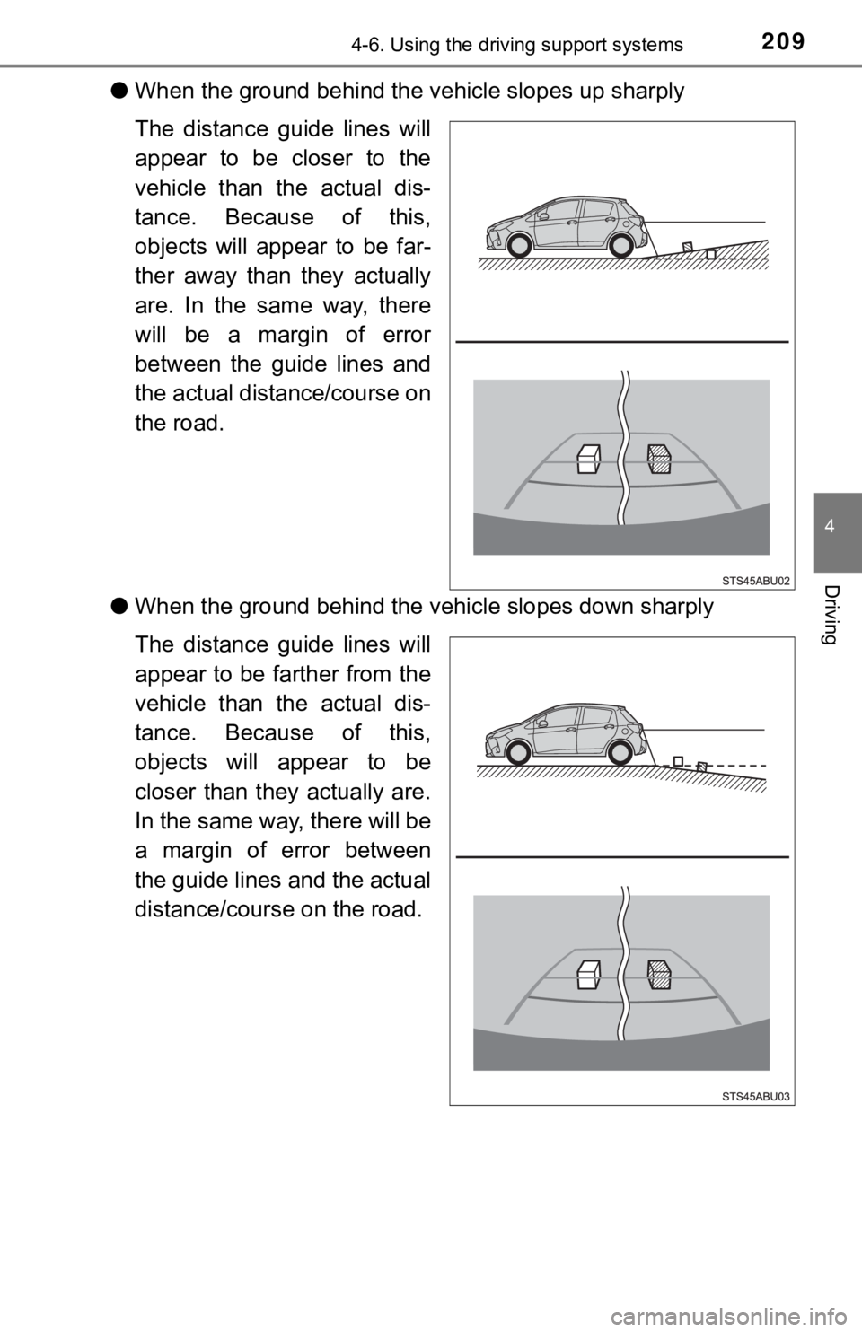
●When the ground behind the vehicle slopes up sharply
The distance guide lines will
appear to be closer to the
vehicle than the actual dis-
tance. Because of this,
objects will appear to be far-
ther away than they actually
are. In the same way, there
will be a margin of error
between the guide lines and
the actual distance/course on
the road.
● When the ground behind the vehi cle slopes down sharply
The distance guide lines will
appear to be farther from the
vehicle than the actual dis-
tance. Because of this,
objects will appear to be
closer than they actually are.
In the same way, there will be
a margin of error between
the guide lines and the actual
distance/course on the road.
Page 210 of 520
2104-6. Using the driving support systems
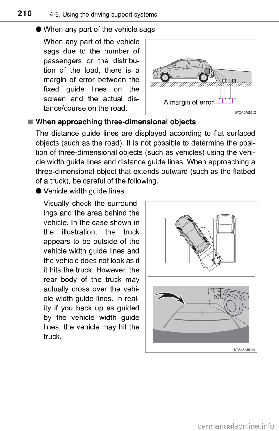
●When any part of the vehicle sags
When any part of the vehicle
sags due to the number of
passengers or the distribu-
tion of the load, there is a
margin of error between the
fixed guide lines on the
screen and the actual dis-
tance/course on the road.
■When approaching thre e-dimensional objects
The distance guide lines are displayed according to flat surfaced
objects (such as the road). It is not possible to determine the posi-
tion of three-dimensional objects (s uch as vehicles) using the vehi-
cle width guide lines and distance guide lines. When approaching a
three-dimensional object that extends outward (such as the flatbed
of a truck), be careful of the following.
● Vehicle width guide lines
Visually check the surround-
ings and the area behind the
vehicle. In the case shown in
the illustration , the truck
appears to be outside of the
vehicle width guide lines and
the vehicle does not look as if
it hits the truck. However, the
rear body of the truck may
actually cross over the vehi-
cle width guide lines. In real-
ity if you back up as guided
by the vehicle width guide
lines, the vehicle may hit the
truck.
A margin of error