VAUXHALL ANTARA 2015 Owner's Manual
Manufacturer: VAUXHALL, Model Year: 2015, Model line: ANTARA, Model: VAUXHALL ANTARA 2015Pages: 223, PDF Size: 6.07 MB
Page 161 of 223

Vehicle care159
Retrofitted electrical or electronic
accessories can place an additional load on the vehicle battery or
discharge the battery. Seek the
assistance of a workshop regarding technical possibilities, such as fitting
a more powerful battery.
Ensure the ignition is switched off
before reconnecting the vehicle
battery. Then perform the following actions:
1. Set date and time in the information display 3 77.
2. If necessary, activate the power windows and sun roof 3 30, 3 32.
In order to prevent the vehicle battery
from discharging, some consumers
such as the courtesy lights
automatically switch off after a delay.
Charge a disconnected vehicle
battery every 6 weeks.
Vehicle battery discharge protection
3 114.Replacing the vehicle battery
Notice
Any deviation from the instructions
given in this paragraph may lead to
a temporary deactivation of the stop-
start system.
When the vehicle battery is being
replaced, please ensure that there
are no open ventilation holes in the
vicinity of the positive terminal. If a
ventilation hole is open in this area, it
must be closed off with a dummy cap, and the ventilation in the vicinity of the
negative terminal must be opened.
Only use batteries that allow the fuse
box to be mounted above the vehicle
battery.
In vehicles with stop-start system,
ensure to have the AGM (Absorptive
Glass Mat) vehicle battery replaced
with an AGM battery again.
An AGM battery can be identified by
the label on the battery. We
recommend the use of an original
Vauxhall battery.
Notice
Using an AGM vehicle battery
different from the original Vauxhall
vehicle battery may result in a lower performance of the stop-start
system.
We recommend that you have the
vehicle battery replaced by a
workshop.
Stop-start system 3 125.
Page 162 of 223

160Vehicle care
Charging the vehicle battery9Warning
On vehicles with stop-start
system, ensure that the charging potential does not exceed
14.6 volts when using a battery
charger. Otherwise the vehicle
battery might be damaged.
Jump starting 3 190.
Warning label
Meaning of symbols: ■ No sparks, naked flames or smoking.
■ Always shield eyes. Explosive gases can cause blindness or
injury.
■ Keep the vehicle battery out of reach of children.
■ The vehicle battery contains sulfuric acid which could cause
blindness or serious burn injuries.
■ See the Owner's Manual for further
information.
■ Explosive gas may be present in the vicinity of the vehicle battery.Diesel fuel filter
Drain diesel fuel filter of residual
water at every engine oil change.
Place a container underneath the
filter housing. Turn drain plug
anticlockwise using a suitable
screwdriver, to drain off the water.
The filter is drained as soon as diesel fuel emerges from the port. Retighten
the drain plug by turning it clockwise.
With engine switched off, turn ignition
key to ON, wait approx. 5 seconds,
and turn key to LOCK to perform
priming operation. Perform this
Page 163 of 223
Vehicle care161
operation 3 times or more while theengine is switched off, to avoid air
entering the fuel line.
Check diesel fuel filter at shorter
intervals if the vehicle is subjected to
extreme operating conditions.
If there is water in the diesel fuel filter, control indicator U illuminates in the
instrument cluster 3 90. Drain the
water immediately.
Diesel fuel system
bleeding
If the fuel tank has been run dry, the
diesel fuel system must be bled.
Switch on the ignition three times for
15 seconds at a time. Then crank the
engine for a maximum of 40 seconds. If the engine will not start, wait at least 10 seconds before trying
again. If the engine fails to start, seek the assistance of a workshop.Wiper blade replacement
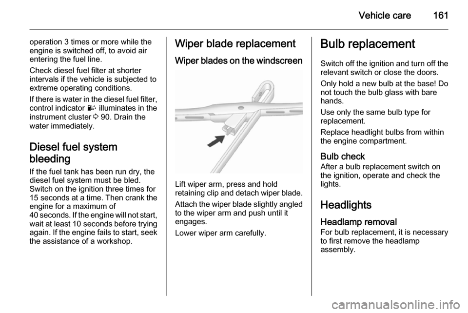
Wiper blades on the windscreen
Lift wiper arm, press and hold
retaining clip and detach wiper blade.
Attach the wiper blade slightly angled
to the wiper arm and push until it
engages.
Lower wiper arm carefully.
Bulb replacement
Switch off the ignition and turn off the
relevant switch or close the doors.
Only hold a new bulb at the base! Do not touch the bulb glass with bare
hands.
Use only the same bulb type for
replacement.
Replace headlight bulbs from within
the engine compartment.
Bulb check After a bulb replacement switch on
the ignition, operate and check the
lights.
Headlights
Headlamp removal For bulb replacement, it is necessary
to first remove the headlamp
assembly.
Page 164 of 223
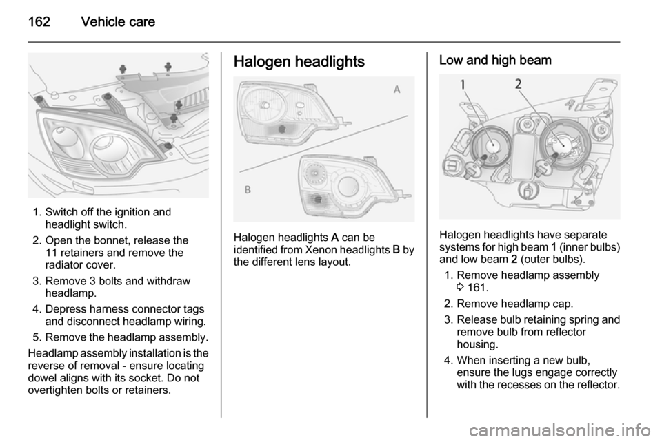
162Vehicle care
1. Switch off the ignition andheadlight switch.
2. Open the bonnet, release the 11 retainers and remove the
radiator cover.
3. Remove 3 bolts and withdraw headlamp.
4. Depress harness connector tags and disconnect headlamp wiring.
5. Remove the headlamp assembly.
Headlamp assembly installation is the
reverse of removal - ensure locating
dowel aligns with its socket. Do not
overtighten bolts or retainers.
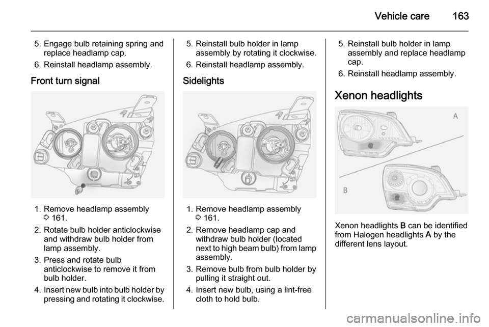
Halogen headlights
Halogen headlights A can be
identified from Xenon headlights B by
the different lens layout.
Low and high beam
Halogen headlights have separate
systems for high beam 1 (inner bulbs)
and low beam 2 (outer bulbs).
1. Remove headlamp assembly 3 161.
2. Remove headlamp cap.
3. Release bulb retaining spring and
remove bulb from reflector
housing.
4. When inserting a new bulb, ensure the lugs engage correctly
with the recesses on the reflector.
Page 165 of 223
Vehicle care163
5. Engage bulb retaining spring andreplace headlamp cap.
6. Reinstall headlamp assembly.
Front turn signal
1. Remove headlamp assembly 3 161.
2. Rotate bulb holder anticlockwise and withdraw bulb holder from
lamp assembly.
3. Press and rotate bulb anticlockwise to remove it from
bulb holder.
4. Insert new bulb into bulb holder by
pressing and rotating it clockwise.
5. Reinstall bulb holder in lamp assembly by rotating it clockwise.
6. Reinstall headlamp assembly.
Sidelights
1. Remove headlamp assembly 3 161.
2. Remove headlamp cap and withdraw bulb holder (located
next to high beam bulb) from lamp
assembly.
3. Remove bulb from bulb holder by pulling it straight out.
4. Insert new bulb, using a lint-free cloth to hold bulb.
5. Reinstall bulb holder in lampassembly and replace headlamp
cap.
6. Reinstall headlamp assembly.
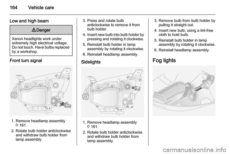
Xenon headlights
Xenon headlights B can be identified
from Halogen headlights A by the
different lens layout.
Page 166 of 223
164Vehicle care
Low and high beam9Danger
Xenon headlights work under
extremely high electrical voltage.
Do not touch. Have bulbs replaced by a workshop.
Front turn signal
1. Remove headlamp assembly 3 161.
2. Rotate bulb holder anticlockwise and withdraw bulb holder from
lamp assembly.
3. Press and rotate bulb anticlockwise to remove it from
bulb holder.
4. Insert new bulb into bulb holder by
pressing and rotating it clockwise.
5. Reinstall bulb holder in lamp assembly by rotating it clockwise.
6. Reinstall headlamp assembly.
Sidelights
1. Remove headlamp assembly 3 161.
2. Rotate bulb holder anticlockwise and withdraw bulb holder from
lamp assembly.
3. Remove bulb from bulb holder by pulling it straight out.
4. Insert new bulb, using a lint-free cloth to hold bulb.
5. Reinstall bulb holder in lamp assembly by rotating it clockwise.
6. Reinstall headlamp assembly.
Fog lights
Page 167 of 223
Vehicle care165
1. Remove 2 screws from panel onunderside of vehicle below front
fog lights and remove panel.
2. Disconnect harness connector from bulb holder and rotate bulb
holder anticlockwise.
3. Remove bulb holder from lamp assembly, rotate bulb
anticlockwise and remove from
bulb holder.
4. Insert new bulb into bulb holder and rotate it clockwise.
5. Reinstall bulb holder in lamp assembly and reconnect harnessconnector.
6. Reinstall panel to underside of vehicle using 2 screws removed
earlier.Tail lights
Rear brake, tail, turn signal,
reverse and fog tail light
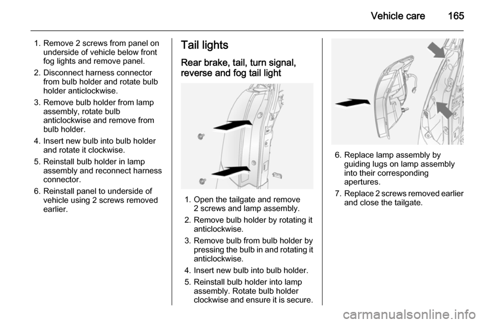
1. Open the tailgate and remove 2 screws and lamp assembly.
2. Remove bulb holder by rotating it anticlockwise.
3. Remove bulb from bulb holder by pressing the bulb in and rotating it
anticlockwise.
4. Insert new bulb into bulb holder.
5. Reinstall bulb holder into lamp assembly. Rotate bulb holder
clockwise and ensure it is secure.
6. Replace lamp assembly by guiding lugs on lamp assembly
into their corresponding
apertures.
7. Replace 2 screws removed earlier
and close the tailgate.
Page 168 of 223
166Vehicle careSide turn signal lights
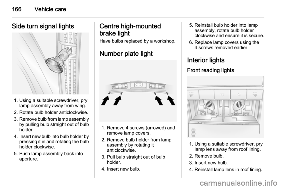
1. Using a suitable screwdriver, prylamp assembly away from wing.
2. Rotate bulb holder anticlockwise.
3. Remove bulb from lamp assembly
by pulling bulb straight out of bulb holder.
4. Insert new bulb into bulb holder by
pressing it in and rotating the bulb holder clockwise.
5. Push lamp assembly back into aperture.
Centre high-mounted
brake light Have bulbs replaced by a workshop.
Number plate light
1. Remove 4 screws (arrowed) and remove lamp covers.
2. Remove bulb holder from lamp assembly by rotating it
anticlockwise.
3. Pull bulb straight out of bulb holder.
4. Insert new bulb.
5. Reinstall bulb holder into lamp assembly, rotate bulb holder
clockwise and ensure it is secure.
6. Replace lamp covers using the 4 screws removed earlier.
Interior lights
Front reading lights
1. Using a suitable screwdriver, pry lamp lens away from roof lining.
2. Remove bulb.
3. Insert new bulb.
4. Reinstall lamp lens in roof lining.
Page 169 of 223

Vehicle care167
Rear reading lights
1. Using a suitable screwdriver, prylamp lens away from roof lining.
2. Remove bulb.
3. Insert new bulb.
4. Reinstall lamp lens in roof lining.
Load compartment light
1. Using a suitable screwdriver, remove lens from lamp assembly.
2. Remove bulb.
3. Insert new bulb.
4. Reinstall lens to lamp assembly.
Glovebox light
Have bulbs replaced by a workshop.
Instrument panel
illumination Have bulbs replaced by a workshop.
Electrical system
Fuses
Data on the replacement fuse must
match the data on the defective fuse.
There are two fuse boxes in the
vehicle:
■ in the engine compartment next to the coolant reservoir,
■ in the instrument panel, on the left- hand side of the front passenger
seat foot well, or, in right-hand drive
vehicles, on the left-hand side of
the driver's seat foot well.
Before replacing a fuse, turn off the
respective switch and the ignition.
A blown fuse can be recognized by its melted wire. Do not replace the fuse
until the cause of the fault has been
remedied.
Some functions are protected by
several fuses. Fuses may also be
inserted without existence of a
function.
Page 170 of 223

168Vehicle care
Notice
Not all fuse box descriptions in this
manual may apply to your vehicle.
When inspecting the fuse box, refer to the fuse box label.
It is advisable to carry a full set of
spare fuses. Spare fuses can be
stored in the engine compartment
fuse box.
Fuse extractor
A fuse extractor may be located in the engine compartment fuse box.
Place the fuse extractor on the
various types of fuse from the top or
side, and withdraw fuse.