check engine light VAUXHALL ANTARA 2015 Owner's Manual
[x] Cancel search | Manufacturer: VAUXHALL, Model Year: 2015, Model line: ANTARA, Model: VAUXHALL ANTARA 2015Pages: 223, PDF Size: 6.07 MB
Page 18 of 223
16In briefTransmission
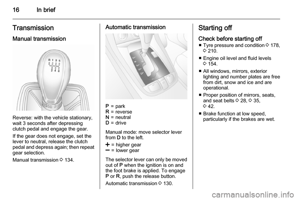
Manual transmission
Reverse: with the vehicle stationary,
wait 3 seconds after depressing
clutch pedal and engage the gear.
If the gear does not engage, set the
lever to neutral, release the clutch
pedal and depress again; then repeat
gear selection.
Manual transmission 3 134.
Automatic transmissionP=parkR=reverseN=neutralD=drive
Manual mode: move selector lever
from D to the left.
<=higher gear]=lower gear
The selector lever can only be moved
out of P when the ignition is on and
the foot brake is applied. To engage
P or R, push the release button.
Automatic transmission 3 130.
Starting off
Check before starting off ■ Tyre pressure and condition 3 178,
3 210.
■ Engine oil level and fluid levels 3 154.
■ All windows, mirrors, exterior lighting and number plates are free
from dirt, snow and ice and are
operational.
■ Proper position of mirrors, seats, and seat belts 3 28, 3 35,
3 42.
■ Brake function at low speed, particularly if the brakes are wet.
Page 29 of 223
Keys, doors and windows27
If the alarm has been triggered, the
hazard warning lights will not flash
upon deactivation.
Alarm When triggered, the alarm sounds via a separate battery-backed power
sounder, and the hazard warning
lights flash simultaneously. The
number and duration of alarm signals
are stipulated by legislation.
The alarm can be silenced by
pressing any button of the radio
remote control or manually unlocking
the driver's door with the ignition key. The anti-theft alarm system is
deactivated at the same time.
If the vehicle's battery is to be
disconnected (e.g. for maintenance
work), the alarm siren must be
deactivated as follows: switch the
ignition on then off, then disconnect
the vehicle's battery within
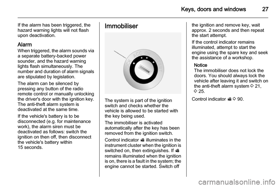
15 seconds.Immobiliser
The system is part of the ignition
switch and checks whether the
vehicle is allowed to be started with the key being used.
The immobiliser is activated
automatically after the key has been
removed from the ignition switch.
Control indicator d illuminates in the
instrument cluster when the ignition is switched on, then extinguishes. If d
remains illuminated when the ignition
is on, there is a fault in the system; the
engine cannot be started. Switch off
the ignition and remove key, wait
approx. 2 seconds and then repeat
the start attempt.
If the control indicator remains
illuminated, attempt to start the
engine using the spare key and seek
the assistance of a workshop.
Notice
The immobiliser does not lock the
doors. You should always lock the
vehicle after leaving it and switch on the anti-theft alarm system 3 21,
3 25.
Control indicator d 3 90.
Page 87 of 223

Instruments and controls85
Interrupt your journey immediately.Remove key and check drive belt
condition and tensioning before
seeking the assistance of a
workshop.
Malfunction indicator light Z illuminates or flashes yellow.
Illuminates when the ignition is
switched on and extinguishes shortly
after the engine starts. If it does not
illuminate, seek the assistance of a
workshop.
Can illuminate briefly when driving;
this is normal and does not indicate a
system fault.
Illuminates when the engine is
running
Fault in the emission control system.
The permitted emission limits may be exceeded. Fuel economy and vehicle
driveability may be impaired. Seek
the assistance of a workshop
immediately.Control indicator Z also illuminates if
there is a fault in the diesel particle
filter 3 128 or with the automatic
transmission 3 133. Seek the
assistance of a workshop as soon as
possible.
Ensure the fuel filler cap is screwed in completely 3 146.
Flashes when the engine is
running
Fault that could lead to catalytic
converter damage 3 129 . Ease up on
the accelerator until the flashing
stops. Seek the assistance of a
workshop immediately.
Service vehicle soon g illuminates yellow.
Illuminates when the engine is
running to indicate a fault in the
engine or transmission electronics. The electronics switch to an
emergency running programme, fuel
consumption may be increased and
vehicle handling may be impaired.In some cases, the fault can be
eliminated by switching the engine off
and back on again. If g illuminates
again after restarting the engine, the vehicle may need a service.
Have the cause of the fault eliminated by a workshop.
Brake system
R illuminates red.
Illuminates when the ignition is
switched on and extinguishes shortly
after the engine starts. If it does not
illuminate, stop and seek the
assistance of a workshop.
If it stays lit while the engine is
running, the brakes do not operate as normal, or leaks are found in the
brake system, do not attempt to drive
the vehicle. Have the vehicle towed to a workshop for inspection and repair.9 Warning
Stop. Do not continue your
journey. Consult a workshop.
Page 102 of 223
100Instruments and controlsVehicle messagesWarning chimes
When starting the engine or whilst driving
Only one warning chime will sound at a time.
The warning chime regarding
unfastened seat belts has priority
over any other warning chime.
■ If seat belt is not fastened.
■ When operating the turn and lane- change signals.
■ When the vehicle is being driven and the electrical parking brake is
applied 3 137.
■ When releasing the electrical parking brake without applying the
foot brake 3 90.
■ If there is a fault in the braking system 3 85.
■ If the parking assist detects an object 3 143.■ During automatic self-cleaning of
the diesel particle filter 3 128.
■ In vehicles equipped with engine overspeed warning; when vehicle
speed exceeds 75 mph 3 91.
When the vehicle is parked and/ or the driver's door is opened ■ When the key is in the ignition switch.
■ With exterior lights on.
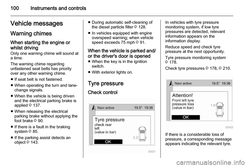
Tyre pressure
Check controlIn vehicles with tyre pressure
monitoring system, if low tyre
pressures are detected, relevant
information appears on the
information display.
Reduce speed and check tyre
pressure at the next opportunity.
Tyre pressure monitoring system
3 178.
Check tyre pressures 3 178, 3 210.
If there is a considerable loss of
pressure, a corresponding message
appears indicating the relevant tyre.
Page 150 of 223

148Driving and operating
If no eye is available, loop cable
around coupling ball bar. Ensure
cable is crossed under the vertical
coupling socket to ensure the trailer
nose cannot drop to the ground if it
becomes separated from the trailer
hitch. Do not allow the cable to drag
along the ground and always allow
enough slack to permit full turning.
Follow the instructions supplied with
the towing equipment.
Before attaching a trailer, lubricate
the coupling ball. However, do not do
so if a stabiliser, which acts on the coupling ball, is being used to reduce snaking movements. For trailers with
low driving stability, the use of a
friction-type stabiliser is strongly
recommended.
Do not drive faster than 50 mph, even
in countries where higher speeds are
permitted. When driving uphill, do not drive faster than 20 mph in 1st gear,
or 30 mph in 2nd gear.
If the trailer starts snaking, drive more slowly, do not attempt to correct the
steering and brake sharply if
necessary.When driving downhill, drive in the
same gear as if driving uphill and
drive at a similar speed.
Adjust tyre pressure to the value
specified for full load 3 210.
Trailer towing Trailer loads
The permissible trailer loads are
vehicle-dependent and engine-
dependent maximum values which
must not be exceeded. The actual
trailer load is the difference between
the actual gross weight of the trailer
and the actual coupling socket load
with the trailer coupled.
When the trailer load is being
checked, therefore, only the trailer
wheels - and not the jockey wheel -
must be standing on the weighing
apparatus.
The permissible trailer loads are
specified in the vehicle documents. In general, they are valid for gradients
up to max. 12 %.The permitted trailer load applies up
to the specified incline and up to an
altitude of 1000 metres above sea
level. Since engine power decreases
as altitude increases due to the air
becoming thinner, therefore reducing
climbing ability, the permissible gross train weight also decreases by 10 %
for every 1000 metres of additional
altitude. The gross train weight does
not have to be reduced when driving
on roads with slight inclines (less than
8 %, e.g. motorways).
The permissible gross train weight
must not be exceeded. This weight is
specified on the identification plate
3 201.
Vertical coupling load
The vertical coupling load is the load
exerted by the trailer on the coupling
ball. It can be varied by changing the
weight distribution when loading the
trailer.
The maximum permissible vertical
coupling load (80 kg) is specified on
the towing equipment identification
plate and in the vehicle documents.
Always aim for the maximum load,
Page 155 of 223

Vehicle care153
■ Open the bonnet, close all doorsand lock the vehicle.
■ Disconnect the clamp from the negative terminal of the vehicle
battery. Beware that all systems are
not functional, e.g. anti-theft alarm
system.
Putting back into operation
When the vehicle is to be put back into
operation:
■ Connect the clamp to the negative terminal of the vehicle battery.
Activate the electronics of the
power windows.
■ Check tyre pressure.
■ Fill up the washer fluid reservoir.
■ Check the engine oil level.
■ Check the coolant level.
■ Fit the number plate if necessary.End-of-life vehicle
recovery
Information on end-of-life vehicle
recovery centres and the recycling of
end-of-life vehicles is available on our website, where legally required. Only
entrust this work to an authorised
recycling centre.Vehicle checks
Performing work9 Warning
Only perform engine compartment
checks when the ignition is off.
The cooling fan may start
operating even if the ignition is off.
9 Danger
The ignition system and Xenon
headlights use extremely high
voltage. Do not touch.
Page 156 of 223
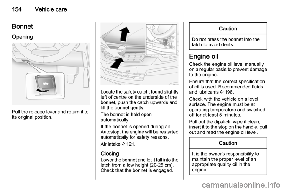
154Vehicle careBonnetOpening
Pull the release lever and return it to
its original position.
Locate the safety catch, found slightly left of centre on the underside of the
bonnet, push the catch upwards and
lift the bonnet gently.
The bonnet is held open
automatically.
If the bonnet is opened during an Autostop, the engine will be restarted automatically for safety reasons.
Air intake 3 121.
Closing
Lower the bonnet and let it fall into the latch from a low height (20-25 cm).
Check that the bonnet is engaged.
Caution
Do not press the bonnet into the
latch to avoid dents.
Engine oil
Check the engine oil level manually on a regular basis to prevent damage
to the engine.
Ensure that the correct specification
of oil is used. Recommended fluids
and lubricants 3 198.
Check with the vehicle on a level
surface. The engine must be at
operating temperature and switched
off for at least 5 minutes.
Pull out the dipstick, wipe it clean, insert it to the stop on the handle, pull
out and read the engine oil level.
Caution
It is the owner's responsibility to
maintain the proper level of an
appropriate quality oil in the
engine.
Page 163 of 223
Vehicle care161
operation 3 times or more while theengine is switched off, to avoid air
entering the fuel line.
Check diesel fuel filter at shorter
intervals if the vehicle is subjected to
extreme operating conditions.
If there is water in the diesel fuel filter, control indicator U illuminates in the
instrument cluster 3 90. Drain the
water immediately.
Diesel fuel system
bleeding
If the fuel tank has been run dry, the
diesel fuel system must be bled.
Switch on the ignition three times for
15 seconds at a time. Then crank the
engine for a maximum of 40 seconds. If the engine will not start, wait at least 10 seconds before trying
again. If the engine fails to start, seek the assistance of a workshop.Wiper blade replacement
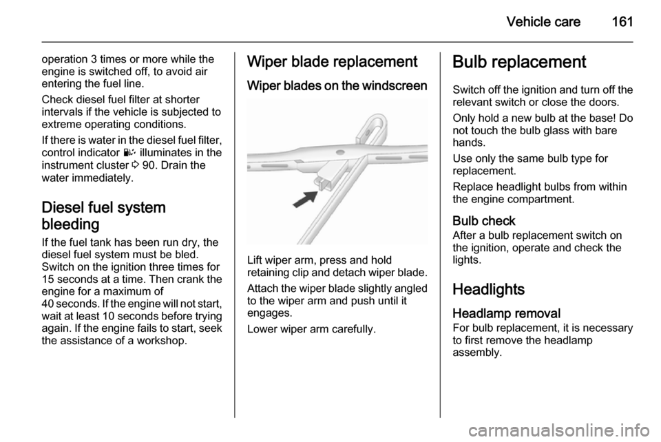
Wiper blades on the windscreen
Lift wiper arm, press and hold
retaining clip and detach wiper blade.
Attach the wiper blade slightly angled
to the wiper arm and push until it
engages.
Lower wiper arm carefully.
Bulb replacement
Switch off the ignition and turn off the
relevant switch or close the doors.
Only hold a new bulb at the base! Do not touch the bulb glass with bare
hands.
Use only the same bulb type for
replacement.
Replace headlight bulbs from within
the engine compartment.
Bulb check After a bulb replacement switch on
the ignition, operate and check the
lights.
Headlights
Headlamp removal For bulb replacement, it is necessary
to first remove the headlamp
assembly.
Page 219 of 223

217
Centre high-mounted brakelight.................................. 110, 166
Change engine oil .......................89
Changing tyre and wheel size ...182
Charging system .......................... 84
Check control.............................. 100
Child locks ................................... 22
Child restraint installation locations ................................... 52
Child restraints.............................. 51
Child restraint systems ................51
Cleaning the vehicle ...................194
Climate control ............................. 15
Climate control systems .............115
Clock ............................................ 77
Clutch fluid ................................. 158
Coin storage ................................. 56
Console box.................................. 58
Console net .................................. 56
Control indicators.......................... 81
Control of the vehicle .................123
Controls ........................................ 73
Controls in steering wheel ............73
Convex shape .............................. 28
Coolant and antifreeze ...............198
Coupling ball bar ........................149
Cruise control ...................... 91, 141
Cupholders .................................. 57
Curtain airbag system .................. 49D
Danger, Warnings and Cautions ...3
Daytime running lights ...............108
Declaration of conformity ............211
Descent control system .......87, 140
Diesel fuel filter .......................... 160
Diesel fuel system bleeding .......161
Diesel particle filter .........85, 88, 128
Door open .................................... 91
Doors ............................................ 23
Drain fuel filter ............................. 90
Drink holders ................................ 57
Driver assistance systems ..........141
Driving characteristics and towing tips .............................. 147
Driving hints ................................ 123
E
Electric adjustment ......................28
Electrical parking brake .......86, 137
Electrical parking brake fault .......86
Electrical system......................... 167
Electronic climate control system 117
Electronic driving programmes ..132
Electronic Stability Control ..87, 139
Electronic Stability Control off ...... 88
End-of-life vehicle recovery .......153
Engine compartment fuse box ...169
Engine coolant ........................... 155Engine coolant temperature ........88
Engine data ............................... 205
Engine exhaust .......................... 128
Engine identification ...................201
Engine oil ................... 154, 198, 202
Engine oil life monitor ...................89
Engine oil pressure ......................89
Entry lighting .............................. 113
Event data recorders ..................213
Exhaust gases ............................ 128
Exit lighting ................................ 113
Exterior care .............................. 194
Exterior lighting ....................12, 106
Exterior mirrors ............................. 28
F
Fault ........................................... 133
Fire extinguisher ........................... 70
First aid kit ................................... 70
Fixed air vents ........................... 121
Flex-Fix system ............................ 58
Fog light ....................................... 91
Fog lights .................... 109, 110, 164
Folding mirrors ............................. 28
Front airbag system .....................47
Front fog lights ........................... 109
Front passenger seat undertray ...57
Front seats.................................... 35
Fuel............................................. 144