VAUXHALL ANTARA 2015 Repair Manual
ANTARA 2015
VAUXHALL
VAUXHALL
https://www.carmanualsonline.info/img/38/19318/w960_19318-0.png
VAUXHALL ANTARA 2015 Repair Manual
Trending: wipers, coolant temperature, set clock, fog light bulb, engine oil capacity, fuel cap release, washer fluid
Page 61 of 223
Storage599Warning
No-one should be in the extension
zone of the rear carrier system,
risk of injury.
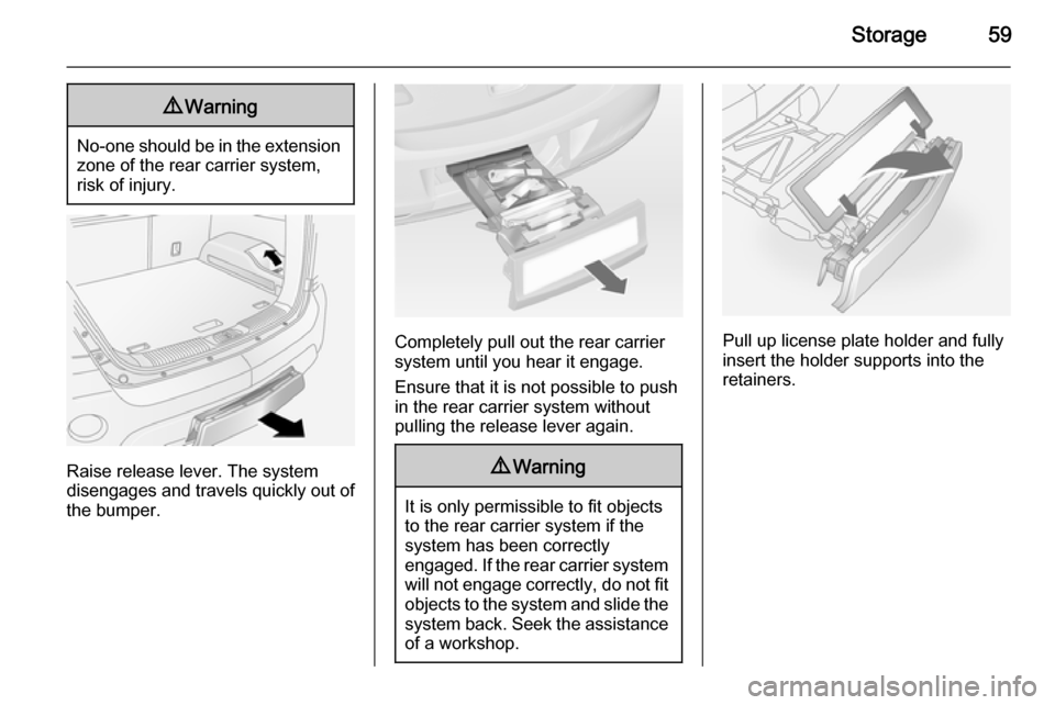
Raise release lever. The system
disengages and travels quickly out of
the bumper.
Completely pull out the rear carrier system until you hear it engage.
Ensure that it is not possible to push
in the rear carrier system without
pulling the release lever again.
9 Warning
It is only permissible to fit objects
to the rear carrier system if the
system has been correctly
engaged. If the rear carrier system will not engage correctly, do not fit
objects to the system and slide the system back. Seek the assistance
of a workshop.
Pull up license plate holder and fully
insert the holder supports into the
retainers.
Page 62 of 223
60Storage
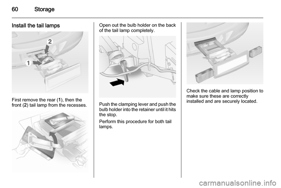
Install the tail lamps
First remove the rear (1), then the
front ( 2) tail lamp from the recesses.
Open out the bulb holder on the back
of the tail lamp completely.
Push the clamping lever and push thebulb holder into the retainer until it hits
the stop.
Perform this procedure for both tail
lamps.
Check the cable and lamp position to
make sure these are correctly
installed and are securely located.
Page 63 of 223
Storage61
Lock the rear carrier system
Swivel the left clamping lever (1) back
first, followed by the right clamping
lever ( 2) until they stop. Both
clamping levers must point
backwards, otherwise safe
functionality is not guaranteed.
Notice
Close the tailgate.
Unfold pedal crank recesses
Fold one or both pedal crank
recesses upwards until the diagonal
support engages.
Remove the pedal crank mounts from
the pedal crank recesses.
Page 64 of 223
62Storage
Adapting the rear carrier systemto a bicycle
With the rotary lever on the pedal
crank recess, roughly adapt the
adjustable pedal crank unit to the
protrusion of the pedal crank.
If the bicycle has straight pedal
cranks, unscrew the pedal crank unit
completely (position 5).
If the bicycle has curved pedal
cranks, screw in the pedal crank unit all the way (position 1).
Press the release lever and withdraw
the wheel recesses.
Push the release lever on the strap
retainer and remove the strap
retainer.
Page 65 of 223
Storage63
Prepare the bicycle for
attachment
Notice
The maximum width for the pedal
crank is 38.3 mm and the maximum
depth is 14.4 mm.
Rotate the left pedal (without a chain
cog) vertically downwards. The pedal
on the left pedal crank must be
horizontal.
The front bicycle must have its front
wheel facing left.
The rear bicycle must have its front
wheel facing right.
Attaching a bicycle to the rear
carrier system
Put on the bicycle. The pedal crank
here must be placed in the pedal
crank recess opening as shown in the
illustration.
Caution
Make sure that the pedal does not
touch the surface of the rear end
carrier. Otherwise the bicycle
chainset might be damaged during transport.
Insert pedal crank mount into outer
rail of each pedal crank recess from
above and slide downwards as far as
it will go.
Page 66 of 223

64Storage
Attach the pedal crank by rotating the
attachment screw on the pedal crank
mount.
Place the wheel recesses such that
the bicycle is more or less horizontal. Here, the distance between the
pedals and the tailgate should be at
least 5 cm.
Both bicycle tyres must be in the
wheel recesses.
Caution
Make sure to pull out the wheel
recesses as far as necessary to have both bicycle tyres placed in
the recesses. Otherwise a
horizontal mounting of the bicycle
is not ensured. Disregard could
lead to damage of the bicycle
wheels caused by hot exhaust
fumes.
Align the bicycle in the longitudinal direction of the vehicle: Slightly
loosen the pedal mount.
Place the bicycle upright using the
rotary lever on the pedal crank
recess.
If the two bicycles obstruct one
another, the relative positions of the
bicycles can be adapted by adjusting
the wheel recesses and the rotary
lever on the pedal crank recess until
the bicycles no longer touch one
another. Make sure there is sufficient
clearance from the vehicle.
Tighten the attachment screw for the
pedal bearing mount to its maximum
point by hand.
Page 67 of 223
Storage65
Secure both bicycle wheels to the
wheel recesses using strap retainers.
Check the bicycle to make sure it is
secure.Caution
Ensure gap between bicycle and
vehicle is at least 5 cm. If
necessary, loosen handlebar and swivel sideways.
The settings for the wheel recesses
and on the rotary lever on the pedal
crank recess should be noted and saved for each bicycle. Correct
presetting will facilitate refitting of the
bicycle.Notice
It is recommended to attach a
warning sign at the rearmost bicycle to increase visibility.
Removing a bicycle from the
rear carrier system
Undo strap retainers on both bicycle
tyres.
Hold on to the bicycle, loosen the attachment screw for the pedal
bearing mount, then lift the pedal
bearing mount to remove it.
Page 68 of 223
66Storage
Retracting the rear carrier
system
Push the pedal crank mounts into the
pedal crank recess as shown in the
illustration.
Insert the strap retainer and pull
tightly downwards as far as possible.
Press release lever and slide in wheel recesses all the way as far as they will
go.
Disengage the locking lever on the
diagonal support and fold both pedal crank recesses down.
9 Warning
Risk of pinching.
Page 69 of 223
Storage67
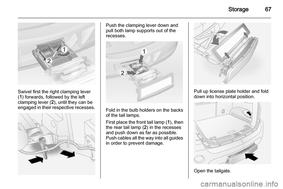
Swivel first the right clamping lever
( 1 ) forwards, followed by the left
clamping lever ( 2), until they can be
engaged in their respective recesses.
Push the clamping lever down and
pull both lamp supports out of the recesses.
Fold in the bulb holders on the backs
of the tail lamps.
First place the front tail lamp ( 1), then
the rear tail lamp ( 2) in the recesses
and push down as far as possible. Push cables all the way into all guides
in order to prevent damage.
Pull up license plate holder and fold
down into horizontal position.
Open the tailgate.
Page 70 of 223
68Storage
Raise the release lever and hold. Liftthe system slightly and push it into the
bumper until it engages.
Release lever must return to original
position.9 Warning
If the system cannot be correctly
engaged, please seek the
assistance of a workshop.
Load compartment
Storage compartments in the
load compartment
Located on both sides of the load
compartment floor.
Load compartment cover Do not place any objects on the cover.
Closing the cover
Pull load compartment cover towards rear of vehicle using handle and insert
retainers into brackets on either side
of load compartment.
Opening the cover
Remove load compartment cover
from side brackets. The cover rolls up automatically.
Trending: oil filter, parking sensors, fuse box location, manual transmission, sunroof, service reset, oil reset


