VAUXHALL COMBO E 2020 Owner's Manual
Manufacturer: VAUXHALL, Model Year: 2020, Model line: COMBO E, Model: VAUXHALL COMBO E 2020Pages: 279, PDF Size: 28.6 MB
Page 201 of 279
Driving and operating199● the change of trajectory is notaccompanied by operation of theturn signals
● the Electronic Stability Control is activated and not in operation
● the vehicle is not connected to a trailer or an electric bicycle carrier
● normal driving behaviour (system
detects dynamic driving style, i.e. pressure on the brake or
accelerator pedal)
● roads with poor lane markings
● no spare wheel is used
● the driver needs to be active during the correction
● the vehicle is not driven in a tight
cornerActivation
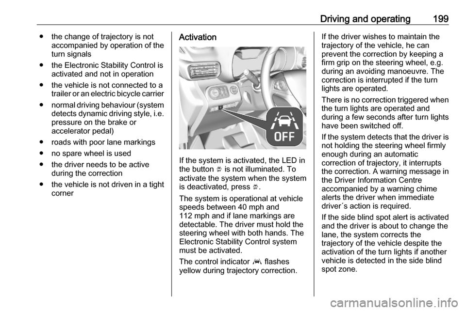
If the system is activated, the LED in
the button Ó is not illuminated. To
activate the system when the system
is deactivated, press Ó.
The system is operational at vehicle
speeds between 40 mph and
112 mph and if lane markings are
detectable. The driver must hold the
steering wheel with both hands. The Electronic Stability Control system
must be activated.
The control indicator a flashes
yellow during trajectory correction.
If the driver wishes to maintain the
trajectory of the vehicle, he can
prevent the correction by keeping a
firm grip on the steering wheel, e.g.
during an avoiding manoeuvre. The correction is interrupted if the turn
lights are operated.
There is no correction triggered when
the turn lights are operated and
during a few seconds after turn lights
have been switched off.
If the system detects that the driver is not holding the steering wheel firmly
enough during an automatic
correction of trajectory, it interrupts
the correction. A warning message in
the Driver Information Centre
accompanied by a warning chime
alerts the driver when immediate
driver´s action is required.
If the side blind spot alert is activated
and the driver is about to change the
lane, the system corrects the
trajectory of the vehicle despite the
activation of the turn lights if another
vehicle is detected in the side blind
spot zone.
Page 202 of 279

200Driving and operatingDeactivation
To deactivate the system, press and
hold Ó. Deactivation of the system is
confirmed by the illuminated LED in
the button. In the Driver Information
Centre solid grey lines are displayed.
Recommended deactivation
It is recommended to deactivate the
system in the following situations:
● Road surface in poor condition
● Unfavourable climatic conditions
● Slippery surfaces, e.g., ice
The system is not designed for driving in the following situations:
● Driving on a speed circuit
● Driving with a trailer
● Driving on a rolling stand
● Driving on unstable surfacesFault
In the event of a fault, a and C
appear in the instrument panel,
accompanied by a display message
and a warning chime. Contact a
dealer or a qualified workshop to have the system checked.
System limitations The system performance may be
affected by:
● windscreen not clean or affected by foreign objects, e.g. stickers
● close vehicles ahead
● banked roads
● narrow, winding or hilly roads
● road edges
● sudden lighting changes
● adverse environmental conditions, e.g. heavy rain or
snow
● vehicle modifications, e.g. tyresSwitch off the system if the system is
disturbed by tar marks, shadows,
road cracks, temporary or
construction lane markings, or other
road imperfections.9 Warning
Always keep your attention on the
road and maintain proper vehicle
position within the lane, otherwise
vehicle damage, injury or death
could occur.
Lane keep assist does not
continuously steer the vehicle.
The system may not keep the
vehicle in the lane or give an alert,
even if a lane marking is detected.
The steering of the lane keep
assist may not be sufficient to
avoid a lane departure.
The system may not detect hands-
off driving due to external
influences like road condition and
surface and weather. The driver has full responsibility to control the
Page 203 of 279

Driving and operating201vehicle and is always required to
keep the hands on the steering
wheel while driving.
Using the system while towing a
trailer or on slippery roads could
cause loss of control of the vehicle
and a crash. Switch the system off.
Driver alert
The driver alert system monitores thedriving time and the vigilance of the
driver. Monitoring the vigilance of the
driver is based on the trajectory
variations of the vehicle compared to
the lane markings.
9 Warning
The system cannot replace the
need for vigilance on the part of
the driver. Taking a break is
recommended as soon as feeling tired or at least every two hours.
Do not take the steering wheel
when feeling tired.
Activation or Deactivation
The system can be activated or
deactivated in the vehicle
personalisation 3 115.
The state of the system stays in
memory when the ignition is switched
off.
Driving time alert The driver gets notified by a pop-up
reminder symbol € in the Driver
Information Centre simultaneously with an acoustic alert if the driver has
not taken a break after 2 hours of
driving at a speed above 40 mph. The alert is repeated hourly until the
vehicle is stopped, no matter how
vehicle speed evolves.The counting of driving time alert is
reset if one of the following conditions is met:
● The vehicle has been stationary for more than 15 minutes with theengine running.
● The ignition has been switched off for a few minutes.
● The driver's seat belt has been unfastened and the driver's door
is open.
Notice
If the vehicle speed drops below
40 mph, the system is paused. The
driving time is counted again once
the speed is above 40 mph.
Driver drowsiness detection
The system monitors the driver's level
of vigilance. A camera at the top of the windscreen detects variations in
trajectory compared to the lane
markings. This system is particularly suited to fast roads (speed higher
than 40 mph).
If the trajectory of the vehicle
suggests a certain level of
drowsiness or inattention by the
Page 204 of 279
202Driving and operatingdriver, the system triggers the first
level of alert. The driver is notified by
a message and an audible signal is
given.
After three first level alerts, the
system triggers a new alert with a message, accompanied by a more
pronounced audible signal.
In certain driving conditions (poor
road surface or strong winds), the
system may give alerts independent of the driver's level of vigilance.
The driver drowsiness detection is
reinitialised when the ignition has
been switched off for a few minutes or the speed remains below 40 mph for
a few minutes.
System limitations
In the following situations, the system
may not operate properly or even not operate at all:
● poor visibility caused by inadequate lighting of the
roadway, falling snow, heavy
rain, dense fog etc.● dazzle caused by headlights of oncoming vehicles, low sun,
reflections on damp roads,
leaving a tunnel, alternating
shade and light etc.
● windscreen area in front of the camera covered by dirt, snow,
stickers etc.
● no lane markings detected or multiple lane markings due to
roadworks
● close vehicles ahead
● winding roads or narrow roadsFuel
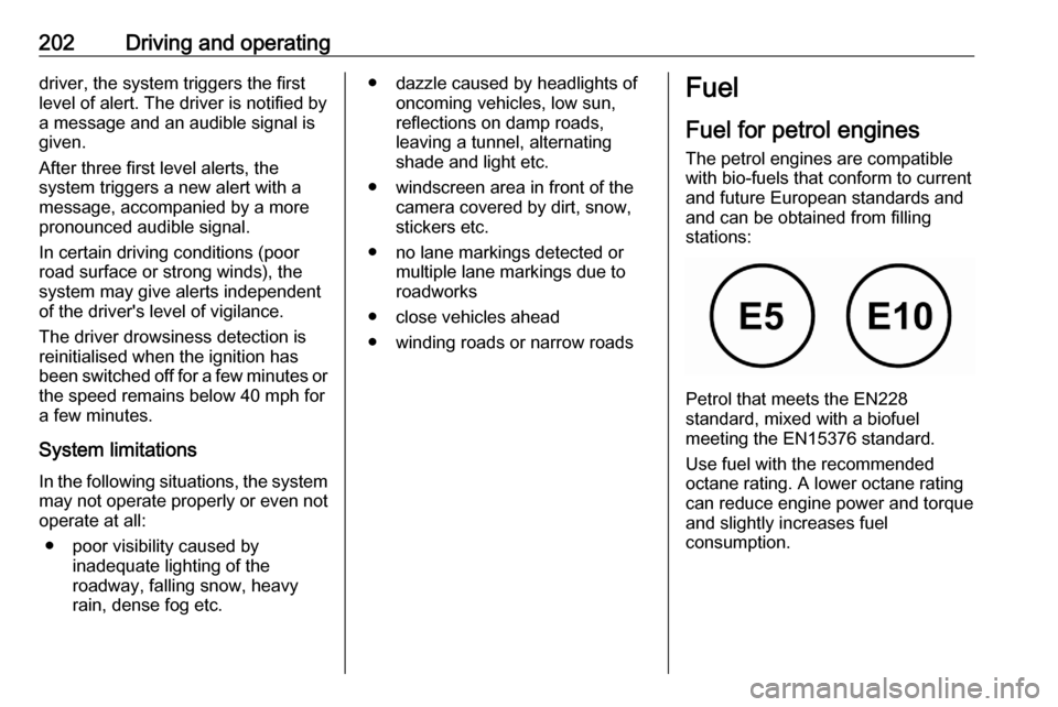
Fuel for petrol engines The petrol engines are compatible
with bio-fuels that conform to current
and future European standards and
and can be obtained from filling
stations:
Petrol that meets the EN228
standard, mixed with a biofuel
meeting the EN15376 standard.
Use fuel with the recommended
octane rating. A lower octane rating
can reduce engine power and torque
and slightly increases fuel
consumption.
Page 205 of 279
Driving and operating203Caution
Do not use fuel or fuel additives
that contain metallic compounds
such as manganese-based
additives. This may cause engine
damage.
Caution
Use of fuel with a lower octane
rating than the lowest possible
rating could lead to uncontrolled combustion and engine damage.
The engine specific requirements
regarding octane rating are given in
the engine data overview 3 260. A
country-specific label at the fuel filler
flap can supersede the requirement.
In certain countries, the use of a
particular fuel, e.g. a specific octane
rating, may be required to ensure
proper engine operation.
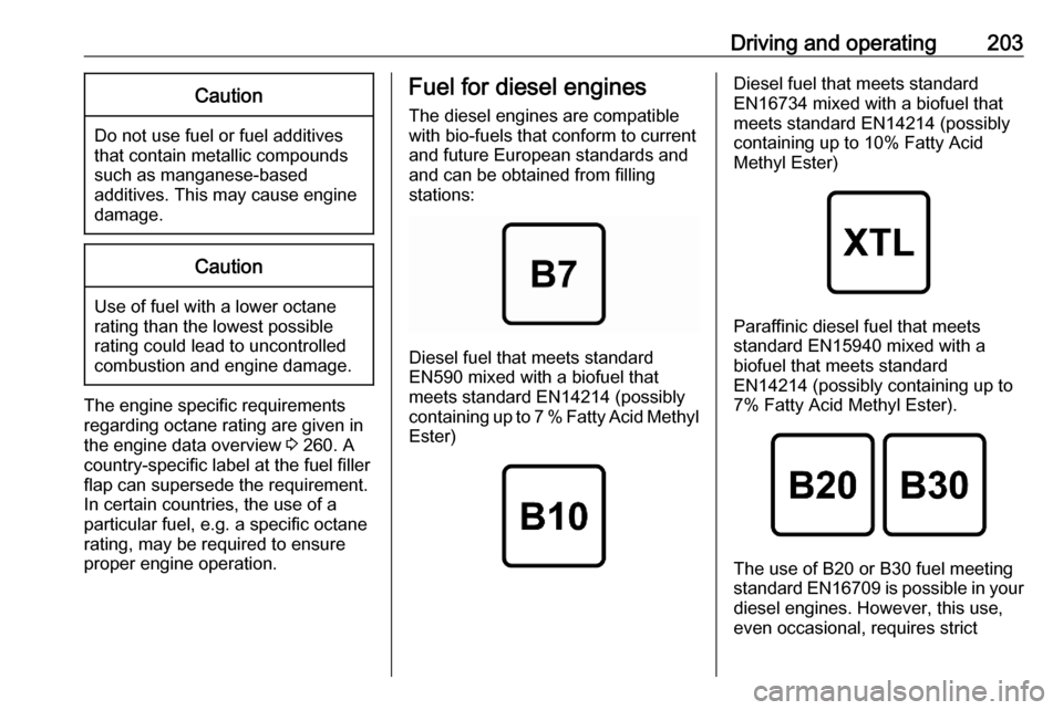
Fuel for diesel engines
The diesel engines are compatible
with bio-fuels that conform to current and future European standards and
and can be obtained from filling
stations:
Diesel fuel that meets standard
EN590 mixed with a biofuel that
meets standard EN14214 (possibly
containing up to 7 % Fatty Acid Methyl Ester)
Diesel fuel that meets standard
EN16734 mixed with a biofuel that
meets standard EN14214 (possibly
containing up to 10% Fatty Acid
Methyl Ester)
Paraffinic diesel fuel that meets
standard EN15940 mixed with a
biofuel that meets standard
EN14214 (possibly containing up to 7% Fatty Acid Methyl Ester).
The use of B20 or B30 fuel meetingstandard EN16709 is possible in your
diesel engines. However, this use,
even occasional, requires strict
Page 206 of 279
204Driving and operatingapplication of the special servicing
conditions referred to as "Arduous
conditions".
For more information, contact a
dealer or a qualified workshop.Caution
The use of any other type of (bio)
fuel (vegetable or animal oils, pure
or diluted, domestic fuel etc.) is
strictly prohibited (risk of damage
to the engine and fuel system).
Notice
The only diesel additives authorised for use are those that meet the
B715000 standard.
Vehicles with diesel engine operating
in Ecuador require the additive
DLP 32-600 to avoid damage of the
injection system. This additive can
only be purchased at Opel dealers.
The additive has to be poured into the
tank before refilling Diesel. For each
50 litres of Diesel refilled, 30 millilitres of additive have to be added. To dose
the additive, use the cap of the
additive can. The cap allows a dose
of 30 millilitres.
Low temperature operation At temperatures below 0 °C, somediesel products with biodiesel blendsmay clog, freeze or gel, which may
affect the fuel supply system. Starting
and engine operation may not work
properly. Make sure to fill winter
grade diesel fuel at ambient
temperatures below 0 °C.
Arctic grade diesel fuel can be used
in extreme cold temperatures below
-20 °C. Using this fuel grade in warm
or hot climates is not recommended
and may cause engine stalling, poor starting or damage on the fuel
injection system.
Refuelling9 Danger
Before refuelling, switch off
ignition and any external heaters
with combustion chambers.
Follow the operating and safety
instructions of the filling station
when refuelling.9 Danger
Fuel is flammable and explosive.
No smoking. No naked flames or
sparks.
If you can smell fuel in your
vehicle, have the cause of this
remedied immediately by a
workshop.
A label with symbols at the fuel filler
flap is indicating the allowed fuel
types. In Europe the pump nozzles of the filling stations are marked with
these symbols. Refuel only the
allowed fuel type.
Caution
In case of misfuelling, do not
switch on ignition.
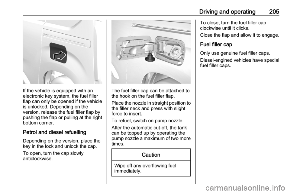
Fuel filler flap is located at left rear
side of vehicle.
Page 207 of 279
Driving and operating205
If the vehicle is equipped with an
electronic key system, the fuel filler
flap can only be opened if the vehicle
is unlocked. Depending on the
version, release the fuel filler flap by
pushing the flap or pulling at the right bottom corner.
Petrol and diesel refuellingDepending on the version, place the
key in the lock and unlock the cap.
To open, turn the cap slowly
anticlockwise.The fuel filler cap can be attached to
the hook on the fuel filler flap.
Place the nozzle in straight position to
the filler neck and press with slight
force to insert.
To refuel, switch on pump nozzle.
After the automatic cut-off, the tank
can be topped up by operating the
pump nozzle a maximum of two more times.
Caution
Wipe off any overflowing fuel
immediately.
To close, turn the fuel filler cap
clockwise until it clicks.
Close the flap and allow it to engage.
Fuel filler cap
Only use genuine fuel filler caps.
Diesel-engined vehicles have special fuel filler caps.
Page 208 of 279

206Driving and operatingTrailer hitch
General information
Only use towing equipment that has
been approved for your vehicle.
Entrust retrofitting of towing
equipment to a workshop. It may be
necessary to make changes that
affect the cooling system, heat
shields or other equipment.
The bulb outage detection function for trailer brake light cannot detect a
partial bulb outage e.g. in case of four
bulbs with a power of 5 W each, the
function only detects lamp outage
when only a single 5 W lamp remains
or none remain.
Fitting of towing equipment could
cover the opening of the towing eye.
If this is the case use the coupling ball bar for towing. Always keep the
coupling ball bar in the vehicle to have
it on hand if needed.Driving characteristics and
towing tips
Before attaching a trailer, lubricate
the coupling ball. However, do not do
so if a stabiliser, which acts on the coupling ball, is being used to reduce snaking movements.
During trailer towing do not exceed a
speed of 50 mph. A maximum speed
of 60 mph is only appropriate if an
oscillation damper is used and the
permissible gross trailer weight does
not exceed the vehicle's curb weight.
For trailers with low driving stability
and caravan trailers, the use of an
oscillation damper is strongly
recommended.
If the trailer starts snaking, drive more slowly, do not attempt to correct the
steering and brake sharply if
necessary.
When driving downhill, drive in the
same gear as if driving uphill and
drive at a similar speed.
Adjust tyre pressure to the value
specified for full load 3 263.Trailer towing
Trailer loadsThe permissible trailer loads are
vehicle and engine-dependent
maximum values which must not be exceeded. The actual trailer load is
the difference between the actual
gross weight of the trailer and the
actual coupling socket load with the trailer coupled.
The permissible trailer loads are
specified in the vehicle documents. In general, they are valid for inclines up
to 12%.
The permissible trailer load applies
up to the specified incline and at sea
level. Since engine power decreases
as altitude increases due to the air
becoming thinner, therefore reducing
climbing ability, the permissible gross
train weight also decreases by 10%
for every 1000 metres of altitude. The gross train weight does not have to be
reduced when driving on roads with
slight inclines (less than 8%, e.g.
motorways).
Page 209 of 279

Driving and operating207The permissible gross train weight
must not be exceeded. This weight is
specified on the identification plate
3 256.
Vertical coupling load
The vertical coupling load is the load
exerted by the trailer on the coupling
ball. It can be varied by changing the
weight distribution when loading the
trailer.
The maximum permissible vertical
coupling load is specified on the
towing equipment identification plate
and in the vehicle documents.
Always aim for the maximum vertical
coupling load, especially in the case
of heavy trailers. The vertical coupling load should never fall below 25 kg.
Rear axle load When the trailer is coupled and the
towing vehicle fully loaded, the
permissible rear axle load (see
identification plate or vehicle
documents) may be exceeded by
60 kg , the gross vehicle weight rating
must not be exceeded. If thepermissible rear axle load is
exceeded, a maximum speed of
60 mph applies.
Towing equipment
Depending on version the vehicle can be fitted with a detachable or a fixed
coupling ball bar.
Type ACaution
When operating without a trailer,
remove the coupling ball bar.
Fitting the coupling ball bar
1. Place the key in the lock and
unlock the coupling ball bar. Move
the lever to the rear position.
2. Clean the contact points with a soft clean cloth.
Page 210 of 279

208Driving and operating3. Insert the coupling ball bar in theopening and push firmly up to the
stop.
Secure the coupling ball bar
correctly by moving the lever to
the locked position, shown in the
picture.
4. Lock the coupling ball bar by turning the key. Remove the key
and close the protective flap.
5. Attach the trailer.
6. Fold the socket forward.
7. Connect the trailer plug to the socket.
8. Attach the breakaway stoppingcable to the eye on the carrier.
9 Warning
Towing a trailer is permitted only
when a coupling ball bar is fitted correctly. If the coupling ball bardoes not engage correctly, seekthe assistance of a workshop.
Dismounting coupling ball bar
1. Disconnect the trailer plug.
2. Unfasten the breakaway stopping
cable.
3. Remove the trailer.
4. Open the protective flap and unlock the coupling ball bar with
the key.
5. Move the lever of the coupling ball
bar to the rear position. Remove
the coupling ball bar by pulling it.