warning VAUXHALL COMBO E 2020 Owner's Guide
[x] Cancel search | Manufacturer: VAUXHALL, Model Year: 2020, Model line: COMBO E, Model: VAUXHALL COMBO E 2020Pages: 279, PDF Size: 28.6 MB
Page 84 of 279
82StorageMoving the partition
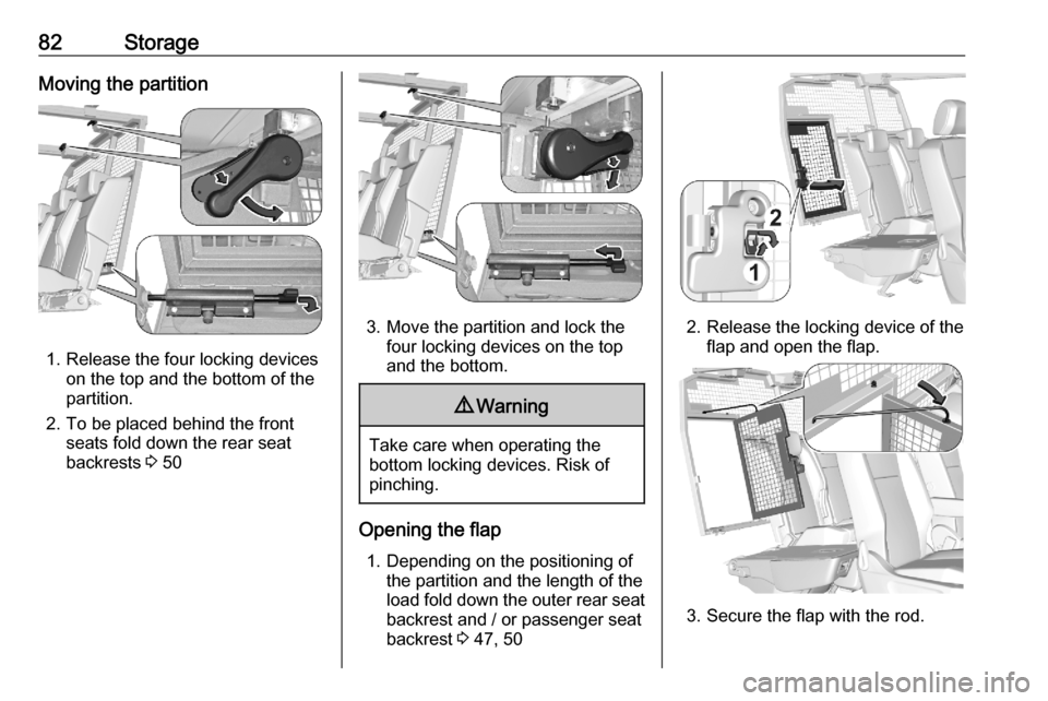
1. Release the four locking deviceson the top and the bottom of the
partition.
2. To be placed behind the front seats fold down the rear seat
backrests 3 50
3. Move the partition and lock the
four locking devices on the top
and the bottom.
9 Warning
Take care when operating the
bottom locking devices. Risk of
pinching.
Opening the flap
1. Depending on the positioning of the partition and the length of the
load fold down the outer rear seat
backrest and / or passenger seat
backrest 3 47, 50
2. Release the locking device of the
flap and open the flap.
3. Secure the flap with the rod.
Page 86 of 279
84Storageside pass one strap on each head
restraint.
With fitted protective cover the
maximum load on each of the folded
backrests is 100 kg.
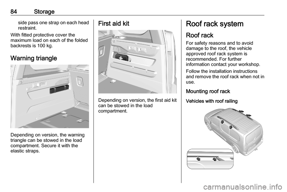
Warning triangle
Depending on version, the warning
triangle can be stowed in the load
compartment. Secure it with the
elastic straps.
First aid kit
Depending on version, the first aid kit can be stowed in the load
compartment.
Roof rack system
Roof rack
For safety reasons and to avoid
damage to the roof, the vehicle
approved roof rack system is
recommended. For further
information contact your workshop.
Follow the installation instructions
and remove the roof rack when not in use.
Mounting roof rack
Vehicles with roof railing
Page 87 of 279
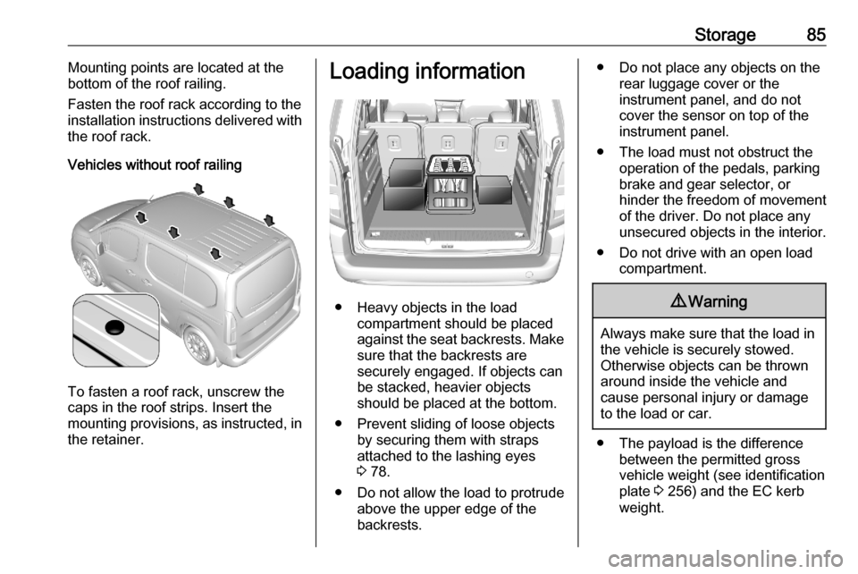
Storage85Mounting points are located at the
bottom of the roof railing.
Fasten the roof rack according to the
installation instructions delivered with
the roof rack.
Vehicles without roof railing
To fasten a roof rack, unscrew the
caps in the roof strips. Insert the
mounting provisions, as instructed, in the retainer.
Loading information
● Heavy objects in the load compartment should be placed
against the seat backrests. Make
sure that the backrests are
securely engaged. If objects can
be stacked, heavier objects
should be placed at the bottom.
● Prevent sliding of loose objects by securing them with straps
attached to the lashing eyes
3 78.
● Do not allow the load to protrude above the upper edge of the
backrests.
● Do not place any objects on the rear luggage cover or the
instrument panel, and do not cover the sensor on top of theinstrument panel.
● The load must not obstruct the operation of the pedals, parking
brake and gear selector, or
hinder the freedom of movement
of the driver. Do not place any
unsecured objects in the interior.
● Do not drive with an open load compartment.9Warning
Always make sure that the load in
the vehicle is securely stowed.
Otherwise objects can be thrown
around inside the vehicle and
cause personal injury or damage
to the load or car.
● The payload is the difference between the permitted gross
vehicle weight (see identification
plate 3 256) and the EC kerb
weight.
Page 90 of 279

88Instruments and controlsInstruments and
controlsControls ....................................... 89
Steering wheel adjustment ........89
Steering wheel controls .............89
Heated steering wheel ...............89
Horn ........................................... 90
Windscreen wiper and washer ..90
Rear window wiper and washer ...................................... 92
Outside temperature ..................92
Clock ......................................... 93
Power outlets ............................. 93
Inductive charging .....................94
Cigarette lighter ......................... 95
Ashtrays .................................... 96
Warning lights, gauges and indi‐ cators ........................................... 96
Instrument cluster ......................96
Speedometer ............................. 97
Odometer .................................. 97
Trip odometer ............................ 97
Tachometer ............................... 98
Fuel gauge ................................ 98
Engine coolant temperature gauge ....................................... 99Engine oil level monitor.............99
Service display .......................... 99
Control indicators ....................100
Turn lights ................................ 100
Seat belt reminder ...................101
Airbag and belt tensioners .......101
Airbag deactivation ..................102
Charging system .....................102
Malfunction indicator light ........102
Service vehicle soon ...............102
Stop engine ............................. 102
System check .......................... 103
Brake and clutch system .........103
Parking brake .......................... 103
Electric parking brake ..............103
Electric parking brake fault ......103
Antilock brake system (ABS) ...104
Gear shifting ............................ 104
Overload indicator ...................104
Descent control system ...........104
Lane keep assist .....................104
Electronic Stability Control and Traction Control system .........104
Engine coolant temperature ....104
Preheating ............................... 105
Exhaust filter ............................ 105
AdBlue ..................................... 105
Deflation detection system ......105
Engine oil pressure ..................105
Low fuel ................................... 106Autostop.................................. 106
Exterior light ............................ 106
High beam ............................... 106
Low beam ................................ 106
High beam assist .....................106
LED headlights ........................ 106
Front fog lights ......................... 106
Rear fog light ........................... 107
Rain sensor ............................. 107
Cruise control .......................... 107
Adaptive cruise control ............107
Side blind spot alert .................107
Active emergency braking .......107
Speed limiter ........................... 107
Door open ................................ 107
Displays ..................................... 108
Driver Information Centre ........108
Info Display .............................. 110
Head-up display ......................112
Rear view display ....................113
Vehicle messages ......................114
Warning chimes .......................114
Vehicle personalisation ..............115
Telematics services ...................119
Vauxhall Connect ....................119
Page 94 of 279
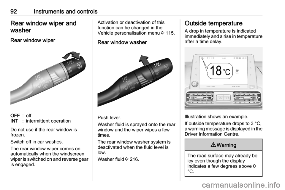
92Instruments and controlsRear window wiper andwasher
Rear window wiperOFF:offINT:intermittent operation
Do not use if the rear window is
frozen.
Switch off in car washes.
The rear window wiper comes on
automatically when the windscreen
wiper is switched on and reverse gear
is engaged.
Activation or deactivation of this
function can be changed in the
Vehicle personalisation menu 3 115.
Rear window washer
Push lever.
Washer fluid is sprayed onto the rear
window and the wiper wipes a few
times.
The rear window washer system is
deactivated when the fluid level is
low.
Washer fluid 3 216.
Outside temperature
A drop in temperature is indicated
immediately and a rise in temperature
after a time delay.
Illustration shows an example.
If outside temperature drops to 3 °C,
a warning message is displayed in the Driver Information Centre.
9 Warning
The road surface may already be
icy even though the display
indicates a few degrees above 0
°C.
Page 96 of 279
94Instruments and controlsDo not connect any current-delivering
accessories, e.g. electrical charging
devices or batteries.
Do not damage the outlet by using
unsuitable plugs.
Stop-start system 3 147.
USB ports
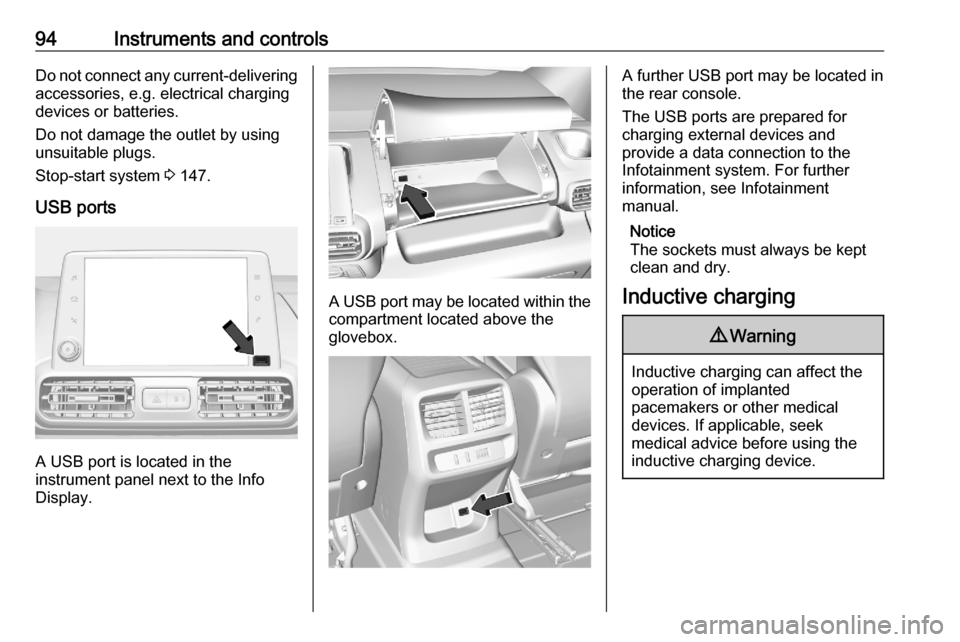
A USB port is located in the
instrument panel next to the Info Display.
A USB port may be located within the
compartment located above the
glovebox.
A further USB port may be located in
the rear console.
The USB ports are prepared for
charging external devices and
provide a data connection to the
Infotainment system. For further
information, see Infotainment
manual.
Notice
The sockets must always be kept
clean and dry.
Inductive charging9 Warning
Inductive charging can affect the
operation of implanted
pacemakers or other medical
devices. If applicable, seek
medical advice before using the
inductive charging device.
Page 97 of 279
Instruments and controls959Warning
Remove any metal objects from
the charging device before
charging a mobile device, as these objects could become very hot.
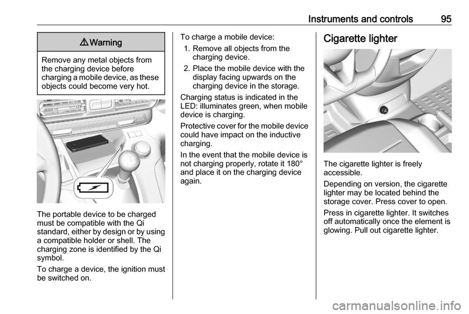
The portable device to be charged
must be compatible with the Qi
standard, either by design or by using a compatible holder or shell. The
charging zone is identified by the Qi
symbol.
To charge a device, the ignition must
be switched on.
To charge a mobile device:
1. Remove all objects from the charging device.
2. Place the mobile device with the display facing upwards on the
charging device in the storage.
Charging status is indicated in the
LED: illuminates green, when mobile
device is charging.
Protective cover for the mobile device
could have impact on the inductive
charging.
In the event that the mobile device is
not charging properly, rotate it 180°
and place it on the charging device
again.Cigarette lighter
The cigarette lighter is freely
accessible.
Depending on version, the cigarette
lighter may be located behind the storage cover. Press cover to open.
Press in cigarette lighter. It switches
off automatically once the element is
glowing. Pull out cigarette lighter.
Page 98 of 279
96Instruments and controlsAshtraysCaution
To be used only for ash and not forcombustible rubbish.
A portable ashtray can be placed in
the cupholders.
Warning lights, gauges
and indicators
Instrument cluster
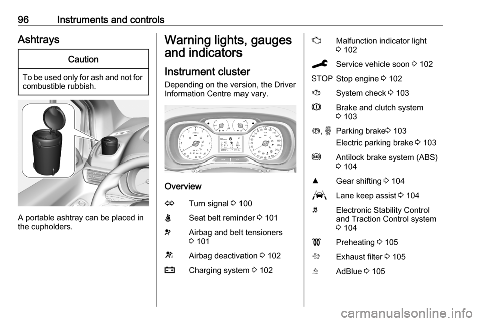
Depending on the version, the Driver Information Centre may vary.
Overview
OTurn signal 3 100XSeat belt reminder 3 101vAirbag and belt tensioners
3 101VAirbag deactivation 3 102pCharging system 3 102ZMalfunction indicator light
3 102CService vehicle soon 3 102YStop engine 3 102JSystem check 3 103RBrake and clutch system
3 103m , oParking brake 3 103
Electric parking brake 3 103uAntilock brake system (ABS)
3 104RGear shifting 3 104LLane keep assist 3 104bElectronic Stability Control
and Traction Control system
3 104!Preheating 3 105%Exhaust filter 3 105YAdBlue 3 105
Page 100 of 279
98Instruments and controls
Monochrome display
Trip odometer counts up to
9,999.9 miles without automatic
reset.
Press L for 2 seconds to reset trip
odometer.
Colour display
Trip odometer counts up to
1,999.9 miles and resets then
automatically.
Press L for 2 seconds to reset trip
odometer.
The trip / fuel information menu provides additionally two trip counter 3 108.
Tachometer
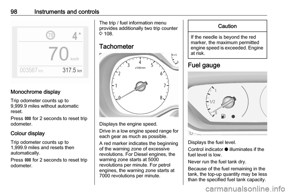
Displays the engine speed.
Drive in a low engine speed range for each gear as much as possible.
A red marker indicates the beginning
of the warning zone of excessive revolutions. For Diesel engines, thewarning zone starts at 5000
revolutions per minute. For petrol
engines, the warning zone starts at
7000 revolutions per minute.
Caution
If the needle is beyond the red marker, the maximum permitted
engine speed is exceeded. Engine at risk.
Fuel gauge
Displays the fuel level.
Control indicator o illuminates if the
fuel level is low.
Never run the fuel tank dry. Because of the fuel remaining in the
tank, the top-up quantity may be less
than the specified fuel tank capacity.
Page 102 of 279
100Instruments and controlsdistance. C flashes and then
illuminates permanently until service
is executed.
Reset of service interval After each service, the service
indicator must be reset to ensure
proper functionality. It is
recommended to seek the assistance of a workshop.
If service is executed by yourself,
operate as following:
● switch off ignition
● press and hold button CHECK
● switch on ignition, the distance indication begins a countdown
● when the display indicates =0,
release the button
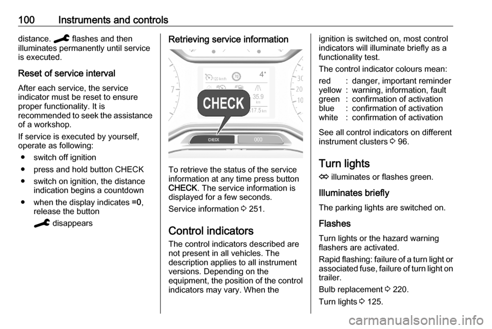
C disappearsRetrieving service information
To retrieve the status of the service
information at any time press button
CHECK . The service information is
displayed for a few seconds.
Service information 3 251.
Control indicators The control indicators described are
not present in all vehicles. The
description applies to all instrument
versions. Depending on the
equipment, the position of the control indicators may vary. When the
ignition is switched on, most controlindicators will illuminate briefly as afunctionality test.
The control indicator colours mean:red:danger, important reminderyellow:warning, information, faultgreen:confirmation of activationblue:confirmation of activationwhite:confirmation of activation
See all control indicators on different
instrument clusters 3 96.
Turn lights
O illuminates or flashes green.
Illuminates briefly The parking lights are switched on.
Flashes
Turn lights or the hazard warning
flashers are activated.
Rapid flashing: failure of a turn light or associated fuse, failure of turn light on
trailer.
Bulb replacement 3 220.
Turn lights 3 125.