VAUXHALL GRANDLAND X 2018 Owner's Manual
Manufacturer: VAUXHALL, Model Year: 2018, Model line: GRANDLAND X, Model: VAUXHALL GRANDLAND X 2018Pages: 263, PDF Size: 7.41 MB
Page 211 of 263
Vehicle care209● See the Owner's Manual forfurther information.
● Explosive gas may be present in the vicinity of the vehicle battery.
Diesel fuel system bleeding If the tank has been run dry, the diesel
fuel system must be bled. Switch on the ignition three times for
15 seconds at a time. Then crank the
engine for a maximum of
40 seconds. Repeat this process after
no less than five seconds. If the
engine fails to start, seek the
assistance of a workshop.Wiper blade replacement
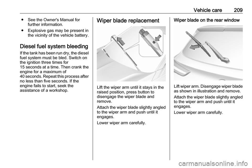
Lift the wiper arm until it stays in the
raised position, press button to
disengage the wiper blade and
remove.
Attach the wiper blade slightly angled
to the wiper arm and push until it
engages.
Lower wiper arm carefully.
Wiper blade on the rear window
Lift wiper arm. Disengage wiper blade as shown in illustration and remove.
Attach the wiper blade slightly angled
to the wiper arm and push until it
engages.
Lower wiper arm carefully.
Page 212 of 263
210Vehicle careBulb replacement
Switch off the ignition and switch off
the relevant switch or close the doors.
Only hold a new bulb at the base. Do not touch the bulb glass with bare
hands.
Use only the same bulb type for
replacement.
Replace headlight bulbs from within
the engine compartment.
Bulb check After a bulb replacement switch on
the ignition, operate and check the
lights.
Halogen headlights
Halogen headlights with separate
bulbs for low beam and high beam.
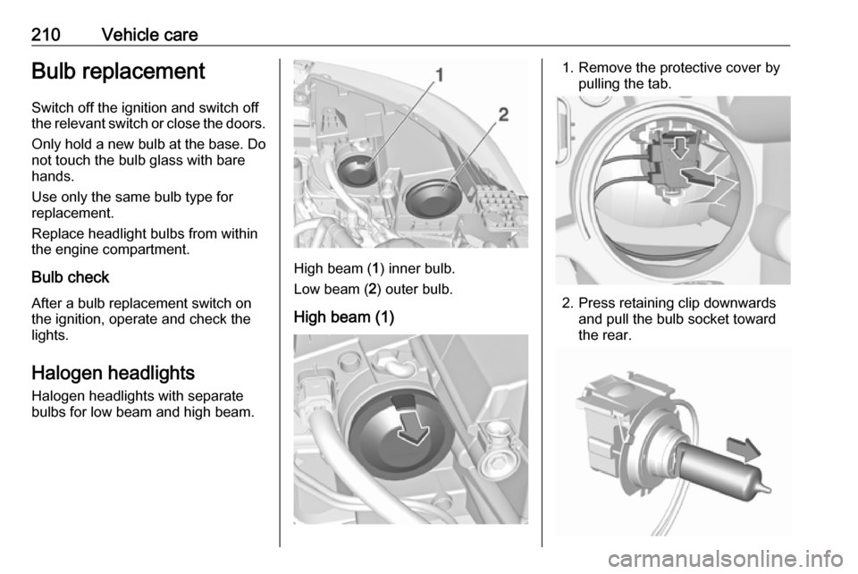
High beam ( 1) inner bulb.
Low beam ( 2) outer bulb.
High beam (1)
1. Remove the protective cover by pulling the tab.
2. Press retaining clip downwardsand pull the bulb socket toward
the rear.
Page 213 of 263
Vehicle care2113. Detach the bulb from the bulbsocket and replace the bulb.
4. Insert the bulb socket into the reflector housing.
5. Fit the cap on.
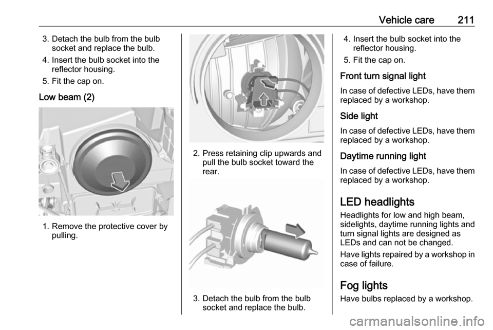
Low beam (2)
1. Remove the protective cover by pulling.
2. Press retaining clip upwards and pull the bulb socket toward the
rear.
3. Detach the bulb from the bulb socket and replace the bulb.
4. Insert the bulb socket into the reflector housing.
5. Fit the cap on.
Front turn signal light In case of defective LEDs, have them
replaced by a workshop.
Side light
In case of defective LEDs, have them replaced by a workshop.
Daytime running light In case of defective LEDs, have them
replaced by a workshop.
LED headlights
Headlights for low and high beam,
sidelights, daytime running lights and turn signal lights are designed as
LEDs and can not be changed.
Have lights repaired by a workshop in
case of failure.
Fog lights
Have bulbs replaced by a workshop.
Page 214 of 263
212Vehicle careTail lightsTail lights, daytime running lights and
centre high-mounted brake light are
designed as LEDs. In case of failure, have LEDs replaced by a workshop.
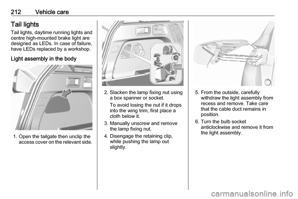
Light assembly in the body
1. Open the tailgate then unclip the access cover on the relevant side.
2. Slacken the lamp fixing nut usinga box spanner or socket.
To avoid losing the nut if it drops
into the wing trim, first place a
cloth below it.
3. Manually unscrew and remove the lamp fixing nut.
4. Disengage the retaining clip, while pushing the lamp out
slightly.5. From the outside, carefully withdraw the light assembly from
recess and remove. Take care
that the cable duct remains in
position.
6. Turn the bulb socket anticlockwise and remove it from
the light assembly.
Page 215 of 263
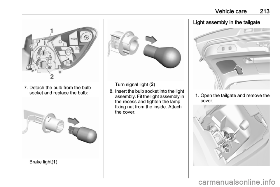
Vehicle care213
7. Detach the bulb from the bulbsocket and replace the bulb:
Brake light( 1)
Turn signal light ( 2)
8. Insert the bulb socket into the light
assembly. Fit the light assembly in the recess and tighten the lamp
fixing nut from the inside. Attach the cover.
Light assembly in the tailgate
1. Open the tailgate and remove the
cover.
Page 216 of 263
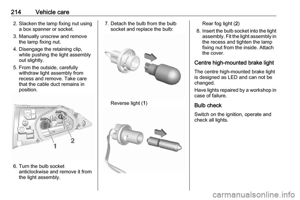
214Vehicle care2. Slacken the lamp fixing nut usinga box spanner or socket.
3. Manually unscrew and remove the lamp fixing nut.
4. Disengage the retaining clip, while pushing the light assembly
out slightly.
5. From the outside, carefully withdraw light assembly from
recess and remove. Take care
that the cable duct remains in
position.
6. Turn the bulb socket anticlockwise and remove it from
the light assembly.
7. Detach the bulb from the bulb socket and replace the bulb:
Reverse light ( 1)
Rear fog light ( 2)
8. Insert the bulb socket into the light
assembly. Fit the light assembly in the recess and tighten the lamp
fixing nut from the inside. Attach
the cover.
Centre high-mounted brake light The centre high-mounted brake light
is designed as LED and can not be
changed.
Have lights repaired by a workshop in
case of failure.
Bulb check
Switch on the ignition, operate and
check all lights.
Page 217 of 263
Vehicle care215Side turn signal lights
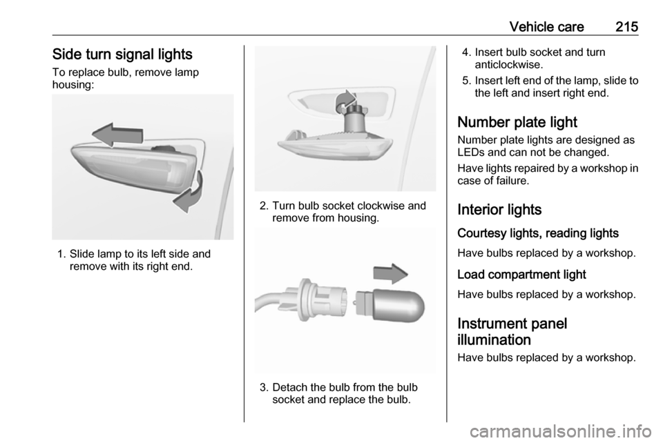
To replace bulb, remove lamp
housing:
1. Slide lamp to its left side and remove with its right end.
2. Turn bulb socket clockwise andremove from housing.
3. Detach the bulb from the bulb socket and replace the bulb.
4. Insert bulb socket and turnanticlockwise.
5. Insert left end of the lamp, slide to
the left and insert right end.
Number plate light Number plate lights are designed as
LEDs and can not be changed.
Have lights repaired by a workshop in
case of failure.
Interior lights
Courtesy lights, reading lights Have bulbs replaced by a workshop.
Load compartment light
Have bulbs replaced by a workshop.
Instrument panel illumination
Have bulbs replaced by a workshop.
Page 218 of 263
216Vehicle careVehicle tools
Tools
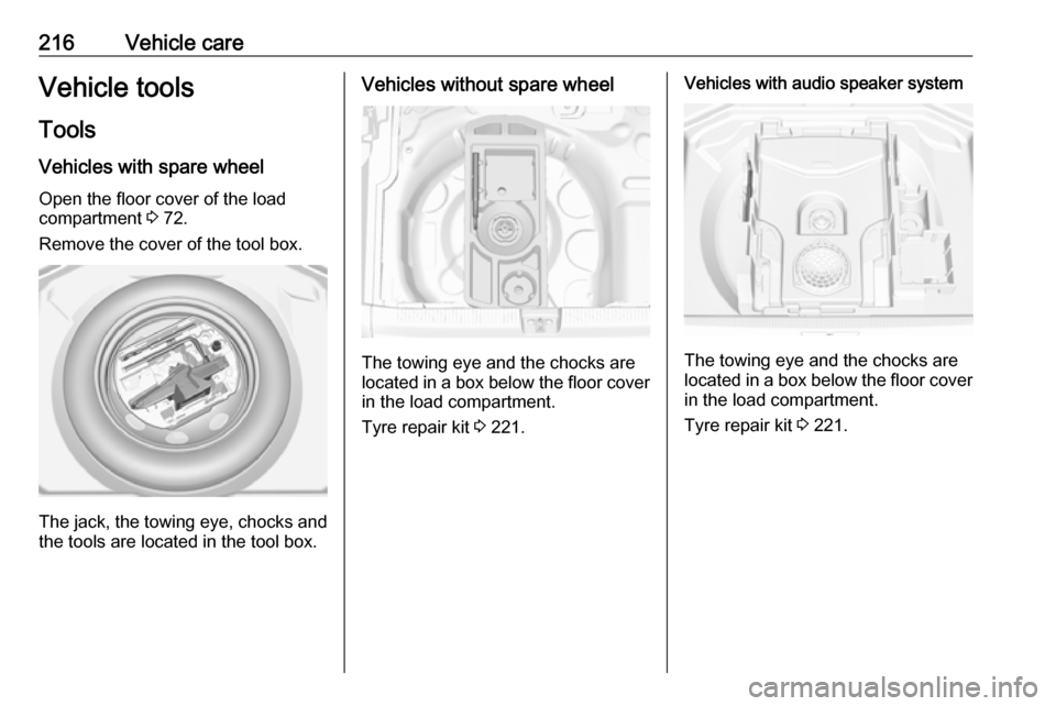
Vehicles with spare wheel Open the floor cover of the load
compartment 3 72.
Remove the cover of the tool box.
The jack, the towing eye, chocks and
the tools are located in the tool box.
Vehicles without spare wheel
The towing eye and the chocks are
located in a box below the floor cover in the load compartment.
Tyre repair kit 3 221.
Vehicles with audio speaker system
The towing eye and the chocks are
located in a box below the floor cover in the load compartment.
Tyre repair kit 3 221.
Page 219 of 263
Vehicle care217Wheels and tyres
Tyre condition, wheel condition
Drive over edges slowly and at right
angles if possible. Driving over sharp
edges can cause tyre and wheel
damage. Do not trap tyres on the kerb when parking.
Regularly check the wheels for
damage. Seek the assistance of a
workshop in the event of damage or
unusual wear.
Winter tyres
Winter tyres improve driving safety at temperatures below 7 °C and should
therefore be fitted on all wheels.
In accordance with country-specific
regulations, affix the speed sticker in
the driver's field of view.
All tyre sizes are permitted as winter
tyres 3 247.Tyre designations
E.g. 225/55 R 18 98 V225:tyre width, mm55:cross-section ratio (tyre height
to tyre width), %R:belt type: RadialRF:type: RunFlat18:wheel diameter, inches98:load index e.g. 98 is equivalent
to 750 kgV:speed code letter
Speed code letter:
Q:up to 100 mphS:up to 112 mphT:up to 118 mphH:up to 130 mphV:up to 150 mphW:up to 168 mph
Choose a tyre appropriate for the
maximum speed of your vehicle.
The maximum speed is achievable at kerb weight with driver (75 kg) plus
125 kg payload. Optional equipment
could reduce the maximum speed of
the vehicle.
Performance 3 244.
Directional tyres
Directional tyres should be mounted
so that they rotate in the correct
direction. The proper rotation
direction is indicated by a symbol
(e.g. an arrow) on the sidewall.
Tyre pressure
Check the pressure of cold tyres at
least every 14 days and before any
long journey. Do not forget the spare
wheel. This also applies to vehicles
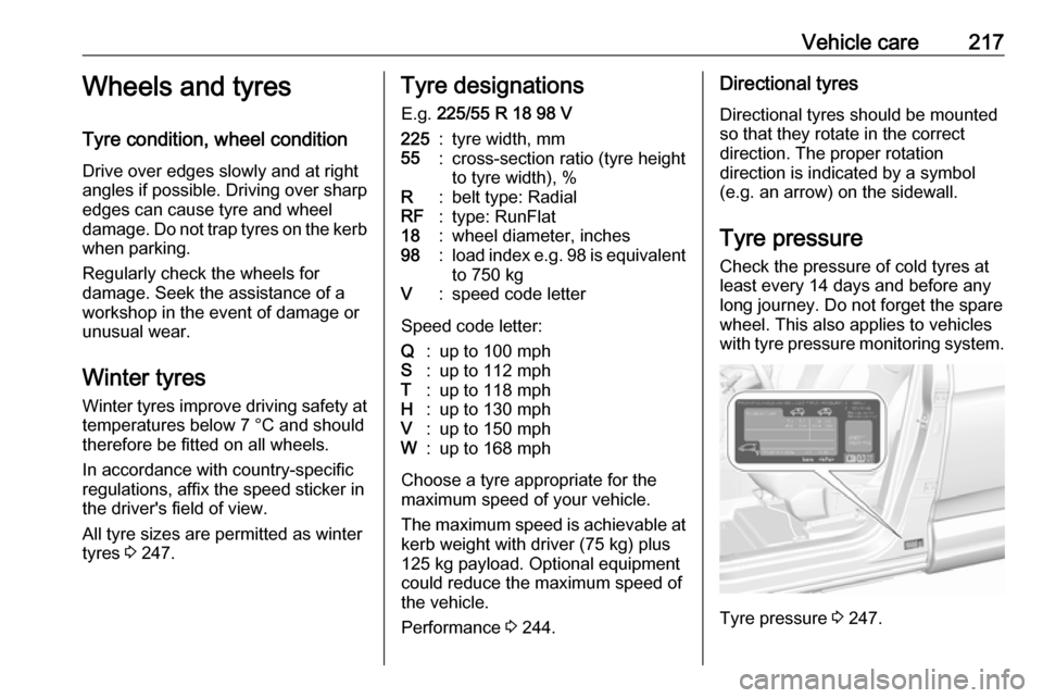
with tyre pressure monitoring system.
Tyre pressure 3 247.
Page 220 of 263
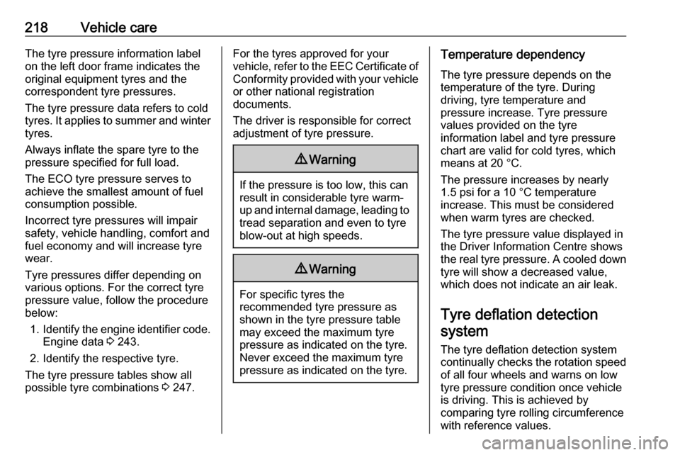
218Vehicle careThe tyre pressure information labelon the left door frame indicates the
original equipment tyres and the
correspondent tyre pressures.
The tyre pressure data refers to cold
tyres. It applies to summer and winter tyres.
Always inflate the spare tyre to the
pressure specified for full load.
The ECO tyre pressure serves to
achieve the smallest amount of fuel
consumption possible.
Incorrect tyre pressures will impair
safety, vehicle handling, comfort and fuel economy and will increase tyre
wear.
Tyre pressures differ depending on
various options. For the correct tyre
pressure value, follow the procedure
below:
1. Identify the engine identifier code.
Engine data 3 243.
2. Identify the respective tyre.
The tyre pressure tables show all
possible tyre combinations 3 247.For the tyres approved for your
vehicle, refer to the EEC Certificate of
Conformity provided with your vehicle
or other national registration
documents.
The driver is responsible for correct
adjustment of tyre pressure.9 Warning
If the pressure is too low, this can
result in considerable tyre warm-
up and internal damage, leading to tread separation and even to tyre
blow-out at high speeds.
9 Warning
For specific tyres the
recommended tyre pressure as
shown in the tyre pressure table may exceed the maximum tyre
pressure as indicated on the tyre.
Never exceed the maximum tyre
pressure as indicated on the tyre.
Temperature dependency
The tyre pressure depends on the
temperature of the tyre. During
driving, tyre temperature and
pressure increase. Tyre pressure
values provided on the tyre
information label and tyre pressure
chart are valid for cold tyres, which means at 20 °C.
The pressure increases by nearly
1.5 psi for a 10 °C temperature
increase. This must be considered
when warm tyres are checked.
The tyre pressure value displayed in
the Driver Information Centre shows
the real tyre pressure. A cooled down
tyre will show a decreased value,
which does not indicate an air leak.
Tyre deflation detectionsystem
The tyre deflation detection system continually checks the rotation speed
of all four wheels and warns on low
tyre pressure condition once vehicle
is driving. This is achieved by
comparing tyre rolling circumference
with reference values.