VAUXHALL GRANDLAND X 2020 Owner's Manual
Manufacturer: VAUXHALL, Model Year: 2020, Model line: GRANDLAND X, Model: VAUXHALL GRANDLAND X 2020Pages: 283, PDF Size: 21.87 MB
Page 201 of 283
Driving and operating199
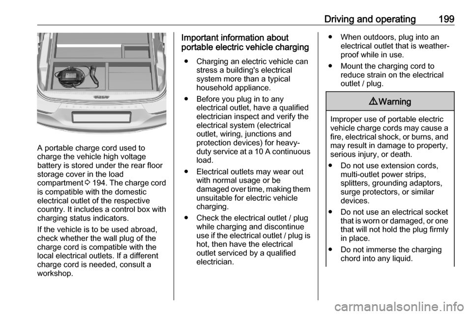
A portable charge cord used to
charge the vehicle high voltage
battery is stored under the rear floor
storage cover in the load
compartment 3 194 . The charge cord
is compatible with the domestic
electrical outlet of the respective
country. It includes a control box with
charging status indicators.
If the vehicle is to be used abroad,
check whether the wall plug of the
charge cord is compatible with the
local electrical outlets. If a different
charge cord is needed, consult a
workshop.
Important information about
portable electric vehicle charging
● Charging an electric vehicle can stress a building's electrical
system more than a typical
household appliance.
● Before you plug in to any electrical outlet, have a qualified
electrician inspect and verify the
electrical system (electrical
outlet, wiring, junctions and
protection devices) for heavy-
duty service at a 10 A continuous
load.
● Electrical outlets may wear out with normal usage or be
damaged over time, making them unsuitable for electric vehicle
charging.
● Check the electrical outlet / plug while charging and discontinue
use if the electrical outlet / plug is
hot, then have the electrical
outlet serviced by a qualified
electrician.● When outdoors, plug into an electrical outlet that is weather-
proof while in use.
● Mount the charging cord to reduce strain on the electricaloutlet / plug.9 Warning
Improper use of portable electric
vehicle charge cords may cause a fire, electrical shock, or burns, and
may result in damage to property,
serious injury, or death.
● Do not use extension cords, multi-outlet power strips,
splitters, grounding adaptors,
surge protectors, or similar
devices.
● Do not use an electrical socket that is worn or damaged, or onethat will not hold the plug firmly
in place.
● Do not immerse the charging chord into any liquid.
Page 202 of 283

200Driving and operating● Do not use an electrical socketthat is not properly grounded.
● Do not use an electrical socket that is on a circuit with other
electrical loads.9 Warning
Read all the safety warnings and
instructions before using this
product. Failure to follow the
warnings and the instructions may result in electric shock, fire, and /
or serious injury.
Never leave children unattended
near the vehicle while the vehicle is charging and never allow
children to play with the charge
cord.
If the plug provided does not fit the electrical outlet, do not modify the
plug. Arrange for a qualified
electrician to inspect the electrical
outlet.
Do not put fingers into the electric
vehicle connector.
1. Vehicle plug
2. Status indicators
3. Wall plug
Charge cord status indicators
After plugging in the charge cord, it
will perform a quick self test and all
status indicators come on for a
moment. Verify the status:
● ! Power
Illuminates yellow: Connection
has been established. The
charge cord is ready to charge
the vehicle.
● 7 Charge
Illuminates green: Charging is
complete.
Flashes green: High voltage
battery is not fully charged.
Charging process is going on or programmable charging is active.
● + Fault
Illuminates red: Fault.
Check whether the connections
to the charge port and to the
electrical outlet are correct. Make
sure that the electrical installation and the charge cord are not
damaged.
If no status indicator comes on, verify the circuit breaker of the electrical
outlet:
● If the circuit breaker has broken, contact a qualified electrician to
verify the compatibility of the electrical installation and repair it.
● If the circuit breaker has not broken, the charge chord may bedefective. Do not use the charge
chord and contact a workshop.
Page 203 of 283
Driving and operating201Grounding instructionsThis product must be grounded. If this
product should malfunction or break
down, grounding provides a path of
least resistance for electric current to
reduce the risk of electric shock. This product is equipped with a cord that
has a grounding conductor. The plug
must be plugged into an appropriate
outlet that is properly installed and
grounded in accordance with all local
codes and ordinances.9 Warning
Improper connection of the charge
cord ground may cause electrical
shock. Check with a qualified
electrician if there is doubt as to
whether the charge circuit is
properly grounded. Do not modify
the plug provided with the product.
If it will not fit the electrical outlet,
have a proper electrical outlet
installed by a qualified electrician.
Fuel
Fuel for petrol engines
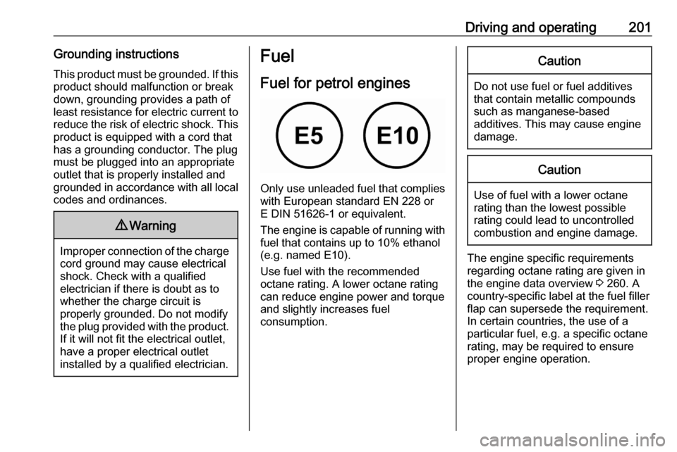
Only use unleaded fuel that complies
with European standard EN 228 or
E DIN 51626-1 or equivalent.
The engine is capable of running with
fuel that contains up to 10% ethanol
(e.g. named E10).
Use fuel with the recommended octane rating. A lower octane rating can reduce engine power and torque
and slightly increases fuel
consumption.
Caution
Do not use fuel or fuel additives
that contain metallic compounds
such as manganese-based
additives. This may cause engine
damage.
Caution
Use of fuel with a lower octane
rating than the lowest possible
rating could lead to uncontrolled combustion and engine damage.
The engine specific requirements
regarding octane rating are given in
the engine data overview 3 260. A
country-specific label at the fuel filler
flap can supersede the requirement.
In certain countries, the use of a
particular fuel, e.g. a specific octane
rating, may be required to ensure
proper engine operation.
Page 204 of 283
202Driving and operatingFuel for diesel enginesThe Diesel engines are compatible
with bio-fuels that conform to current and future European standards and
and can be obtained from filling
stations:
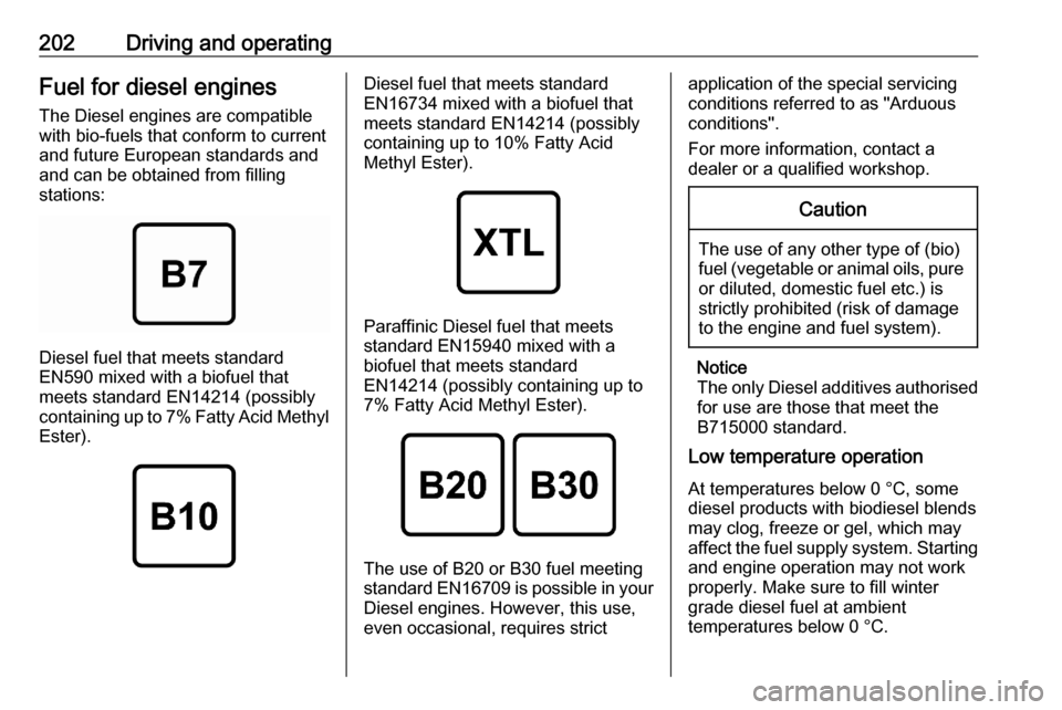
Diesel fuel that meets standard
EN590 mixed with a biofuel that
meets standard EN14214 (possibly
containing up to 7% Fatty Acid Methyl
Ester).
Diesel fuel that meets standard
EN16734 mixed with a biofuel that
meets standard EN14214 (possibly
containing up to 10% Fatty Acid
Methyl Ester).
Paraffinic Diesel fuel that meets
standard EN15940 mixed with a
biofuel that meets standard
EN14214 (possibly containing up to
7% Fatty Acid Methyl Ester).
The use of B20 or B30 fuel meeting standard EN16709 is possible in your
Diesel engines. However, this use,
even occasional, requires strict
application of the special servicing
conditions referred to as "Arduous
conditions".
For more information, contact a
dealer or a qualified workshop.Caution
The use of any other type of (bio)
fuel (vegetable or animal oils, pure
or diluted, domestic fuel etc.) is
strictly prohibited (risk of damage
to the engine and fuel system).
Notice
The only Diesel additives authorised for use are those that meet the
B715000 standard.
Low temperature operation
At temperatures below 0 °C, some
diesel products with biodiesel blends may clog, freeze or gel, which mayaffect the fuel supply system. Starting
and engine operation may not work
properly. Make sure to fill winter
grade diesel fuel at ambient
temperatures below 0 °C.
Page 205 of 283
Driving and operating203Arctic grade diesel fuel can be used
in extreme cold temperatures below
-20 °C. Using this fuel grade in warm
or hot climates is not recommended
and may cause engine stalling, poor starting or damage on the fuel
injection system.
Refuelling9 Danger
Before refuelling, switch off
ignition and any external heaters
with combustion chambers.
Follow the operating and safety
instructions of the filling station
when refuelling.9 Danger
Fuel is flammable and explosive.
No smoking. No naked flames or
sparks.
If you can smell fuel in your
vehicle, have the cause of this
remedied immediately by a
workshop.
A label with symbols at the fuel filler
flap is indicating the allowed fuel
types. In Europe the pump nozzles of the filling stations are marked with
these symbols. Refuel only the
allowed fuel type.
Caution
In case of misfuelling, do not
switch on ignition.
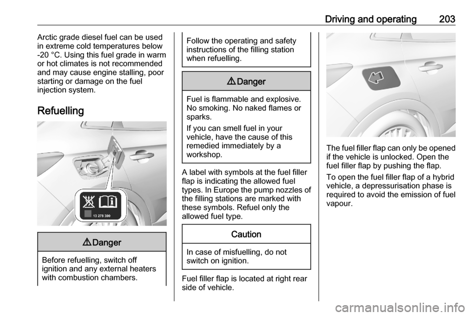
Fuel filler flap is located at right rear
side of vehicle.
The fuel filler flap can only be opened
if the vehicle is unlocked. Open the
fuel filler flap by pushing the flap.
To open the fuel filler flap of a hybrid
vehicle, a depressurisation phase is
required to avoid the emission of fuel
vapour.
Page 206 of 283
204Driving and operating
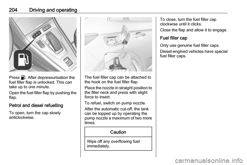
Press r. After depressurisation the
fuel filler flap is unlocked. This can
take up to one minute.
Open the fuel filler flap by pushing the flap.
Petrol and diesel refuelling
To open, turn the cap slowly
anticlockwise.The fuel filler cap can be attached to the hook on the fuel filler flap.
Place the nozzle in straight position to the filler neck and press with slight
force to insert.
To refuel, switch on pump nozzle.
After the automatic cut-off, the tank can be topped up by operating the
pump nozzle a maximum of two more
times.
Caution
Wipe off any overflowing fuel
immediately.
To close, turn the fuel filler cap
clockwise until it clicks.
Close the flap and allow it to engage.
Fuel filler cap
Only use genuine fuel filler caps.
Diesel-engined vehicles have special fuel filler caps.
Page 207 of 283

Driving and operating205Trailer hitch
General information
Only use towing equipment that has
been approved for your vehicle. If
using non-factory fitted towing
equipment, deactivation of the hands- free tailgate operation may be
required 3 29.
Entrust retrofitting of towing
equipment to a workshop. It may be
necessary to make changes that
affect the cooling system, heat
shields or other equipment.
The bulb outage detection function for trailer brake light cannot detect a
partial bulb outage. E.g. in case of
four bulbs with a power of 5 W each,
the function only detects light outage
when only a single 5 W light remains
or none remain.
Trailers equipped with LED lights are
not suitable for the wiring harness of
this trailer hitch.
Fitting of towing equipment could
cover the opening of the towing eye.
If this is the case use the coupling ballbar for towing. Always keep the
coupling ball bar in the vehicle to have it on hand if needed.
Driving characteristics and towing tips
Before attaching a trailer, lubricatethe coupling ball. However, do not do
so if a stabiliser, which acts on the coupling ball, is being used to reduce
snaking movements.
During trailer towing do not exceed a
speed of 50 mph. A maximum speed
of 60 mph is only appropriate if an oscillation damper is used and the
permissible gross trailer weight does
not exceed the vehicle's curb weight.
For trailers with low driving stability
and caravan trailers, the use of an
oscillation damper is strongly
recommended.
If the trailer starts snaking, drive more slowly, do not attempt to correct the
steering and brake sharply if
necessary.
When driving downhill, drive in the
same gear as if driving uphill and
drive at a similar speed.Adjust tyre pressure to the value
specified for full load 3 266.
Trailer towing
Trailer loads The permissible trailer loads are
vehicle and engine-dependent
maximum values which must not be
exceeded. The actual trailer load is
the difference between the actual
gross weight of the trailer and the
actual coupling socket load with the
trailer coupled.
The permissible trailer loads are
specified in the vehicle documents. In general, they are valid for inclines up
to 12%.
The permissible trailer load applies
up to the specified incline and at sea
level. Since engine power decreases
as altitude increases due to the air
becoming thinner, therefore reducing
climbing ability, the permissible gross
train weight also decreases by 10%
for every 1000 m of altitude. The
gross train weight does not have to be
Page 208 of 283
206Driving and operatingreduced when driving on roads with
slight inclines (less than 8%, e.g.
motorways).
The permissible gross train weight
must not be exceeded. This weight is
specified on the identification plate
3 256.
Vertical coupling load The vertical coupling load is the load
exerted by the trailer on the coupling
ball. It can be varied by changing the
weight distribution when loading the
trailer.
The maximum permissible vertical
coupling load (70 kg) is specified on
the towing equipment identification
plate and in the vehicle documents.
Always aim for the maximum vertical
coupling load, especially in the case
of heavy trailers. The vertical coupling
load should never fall below 25 kg.Rear axle load
When the trailer is coupled and the
towing vehicle fully loaded, the
permissible rear axle load (see
identification plate or vehicle
documents) may be exceeded by
60 kg , the gross vehicle weight rating
must not be exceeded. If the
permissible rear axle load is
exceeded, a maximum speed of
60 mph applies.
Towing equipmentCaution
When operating without a trailer,
remove the coupling ball bar.
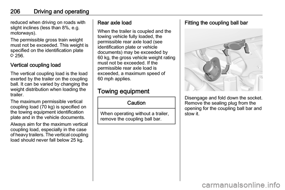
Fitting the coupling ball bar
Disengage and fold down the socket. Remove the sealing plug from the
opening for the coupling ball bar and
stow it.
Page 209 of 283

Driving and operating207Checking the tensioning of the
coupling ball bar
● Red marking on rotary knob must
point towards green marking on
coupling ball bar.
● The gap between the rotary knob
and the coupling ball bar must be approx. 6 mm.
● Remove the cover from the lock of the rotary knob and verify
whether the rotary knob is
locked. If the rotary knob cannot be turned, it is locked.
Otherwise, the coupling ball bar must be tensioned before being inserted:
● Unlock coupling ball bar by turning key to position c.● Pull out rotary knob and turn
clockwise as far as it will go.
Inserting the coupling ball bar
Page 210 of 283

208Driving and operatingInsert the tensioned coupling ball bar
in the opening and push firmly
upwards until it audibly engages.
The rotary handle snaps back into its
original position resting against the
coupling ball bar without a gap.9 Warning
Do not touch rotary handle during
insertion.
Lock the coupling ball bar by turning
the key to position e. Remove the key
and close the protective flap.
Eye for break-away stopping cable
Attach breakaway stopping cable to
eye.
Check that the coupling ball bar is correctly installed
● Green marking on rotary knob must point towards green
marking on coupling ball bar.
● There must be no gap between the rotary handle and the
coupling ball bar.
● The coupling ball bar must be firmly engaged in the opening.
● The coupling ball bar must be locked and the key removed.9Warning
Towing a trailer is permitted only
when a coupling ball bar is fitted correctly. If the coupling ball bardoes not engage correctly, seekthe assistance of a workshop.
Dismounting the coupling ball bar
Open the protective flap and turn the
key to position c to unlock the
coupling ball bar.
Pull out rotary handle and turn
clockwise as far as it will go. Pull out coupling ball bar downwards.
Insert sealing plug in opening. Fold away socket.
Trailer stability assist
If the system detects snaking
movements, engine power is reduced
and the vehicle / trailer combination is