VAUXHALL MOVANO_B 2014 Owner's Manual
Manufacturer: VAUXHALL, Model Year: 2014, Model line: MOVANO_B, Model: VAUXHALL MOVANO_B 2014Pages: 201, PDF Size: 4.74 MB
Page 151 of 201
Vehicle care149
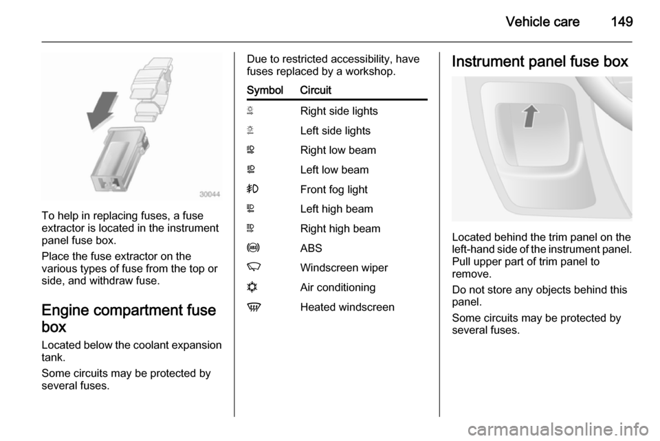
To help in replacing fuses, a fuse
extractor is located in the instrument
panel fuse box.
Place the fuse extractor on the
various types of fuse from the top or
side, and withdraw fuse.
Engine compartment fusebox
Located below the coolant expansion tank.
Some circuits may be protected by
several fuses.
Due to restricted accessibility, have
fuses replaced by a workshop.SymbolCircuitSRight side lightsTLeft side lightsWRight low beamaLeft low beam>Front fog lightLLeft high beamNRight high beamuABSKWindscreen wipernAir conditioningVHeated windscreenInstrument panel fuse box
Located behind the trim panel on the
left-hand side of the instrument panel. Pull upper part of trim panel to
remove.
Do not store any objects behind this
panel.
Some circuits may be protected by
several fuses.
Page 152 of 201
150Vehicle care
SymbolCircuitZInfotainment system, seat
heating, vehicle display
screen, audio connections,
alarm?Power outletÌCigarette lightereInstrument panelUCentral lockingOTurn signals, rear fog lights, body control moduleDIAGDiagnostic connectoruABS, Electronic stability
programdInterior lights, brake lightsZBody control moduleSTOPBrake lightIBody control module, power windows, air conditioningmLeft heated rear windowSymbolCircuitnRight heated rear windowRWindscreen washerMElectronic immobiliserUHeated seatsFBLCornering lightlHands-free connection&TachographPTOPower take-offjHornÍPreheating, diesel fuel filterxClimate control fanADPAdditional adaptations,Power windows, body
control moduleVehicle tools
Tools
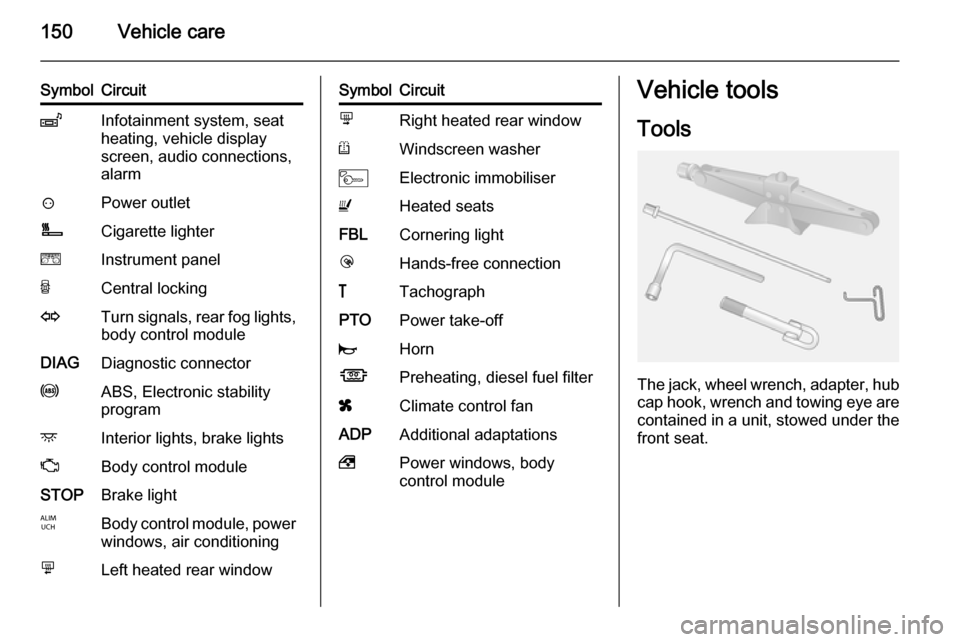
The jack, wheel wrench, adapter, hubcap hook, wrench and towing eye are
contained in a unit, stowed under the front seat.
Page 153 of 201
Vehicle care151
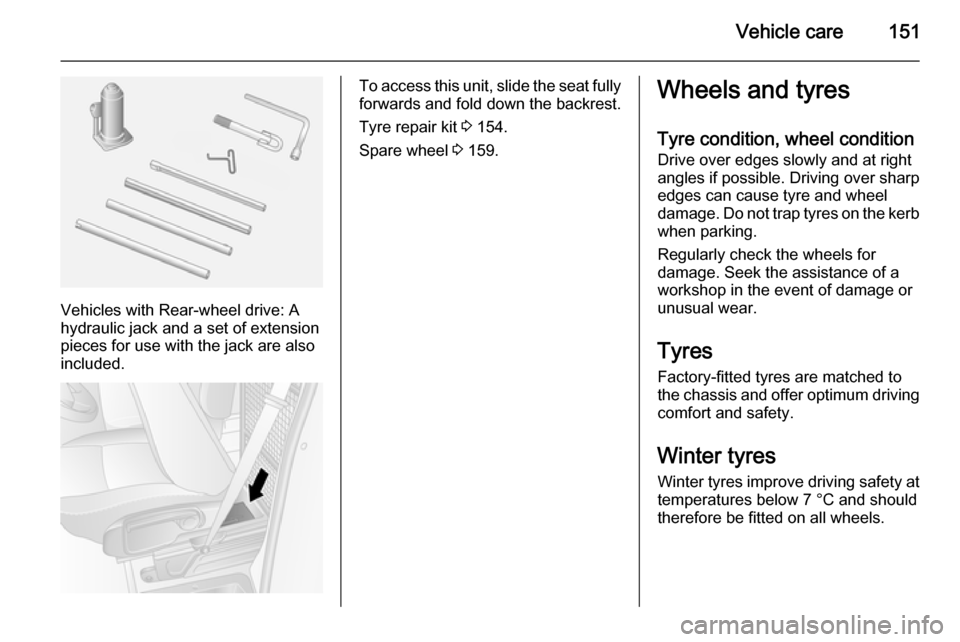
Vehicles with Rear-wheel drive: A
hydraulic jack and a set of extension
pieces for use with the jack are also
included.
To access this unit, slide the seat fully forwards and fold down the backrest.
Tyre repair kit 3 154.
Spare wheel 3 159.Wheels and tyres
Tyre condition, wheel condition
Drive over edges slowly and at right
angles if possible. Driving over sharp
edges can cause tyre and wheel
damage. Do not trap tyres on the kerb
when parking.
Regularly check the wheels for
damage. Seek the assistance of a
workshop in the event of damage or
unusual wear.
Tyres Factory-fitted tyres are matched to
the chassis and offer optimum driving comfort and safety.
Winter tyres Winter tyres improve driving safety at
temperatures below 7 °C and should
therefore be fitted on all wheels.
Page 154 of 201
152Vehicle care
In accordance with country-specific
regulations, a notice indicating the
maximum permissible speed for the
tyres must be affixed within the
driver's field of vision.
Tyre designationsE.g. 215/65 R 16 C 109 R215=Tyre width, mm65=Cross-section ratio (tyre
height to tyre width), %R=Belt type:RadialRF=Type:RunFlat16=Wheel diameter, inchesC=Cargo or commercial use88=Load index e.g. 109 is
equivalent to approx.
1030 kgR=Speed code letter
Speed code letter:
Q=up to 100 mphS=up to 112 mphT=up to 118 mphH=up to 130 mphV=up to 150 mphW=up to 168 mphTyre pressure
Check the pressure of cold tyres at least every 14 days and before any
long journey. Do not forget the spare
wheel.
Tyre pressures 3 189.
The tyre pressure data refers to cold tyres. It applies to summer and winter tyres.
Always inflate the spare tyre to the
pressure specified for full load.
Incorrect tyre pressures will impair
safety, vehicle handling, comfort and
fuel economy and will increase tyre
wear.9 Warning
If the pressure is too low, this can
result in considerable tyre warm-
up and internal damage, leading to tread separation and even to tyre
blow-out at high speeds.
Rear-wheel drive, with twin rear
wheels When inflating the outer tyre, the
inflation tube should be passed
between the two wheels.
Tread depth
Check tread depth at regular
intervals.
Tyres should be replaced for safety
reasons at a tread depth of 2-3 mm
(4 mm for winter tyres).
For safety reasons it is recommended
that the tread depth of the tyres on
one axle should not vary by more than
2 mm.
Page 155 of 201
Vehicle care153
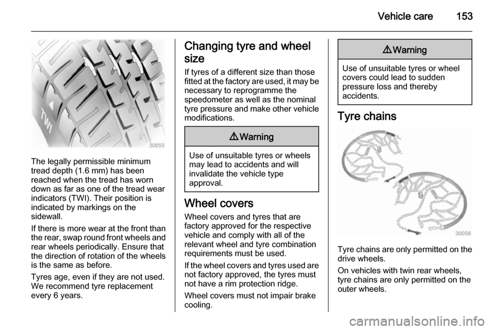
The legally permissible minimum
tread depth (1.6 mm) has been
reached when the tread has worn
down as far as one of the tread wear
indicators (TWI). Their position is
indicated by markings on the
sidewall.
If there is more wear at the front than
the rear, swap round front wheels and rear wheels periodically. Ensure that
the direction of rotation of the wheels
is the same as before.
Tyres age, even if they are not used.
We recommend tyre replacement
every 6 years.
Changing tyre and wheel
size If tyres of a different size than those
fitted at the factory are used, it may be necessary to reprogramme the
speedometer as well as the nominal
tyre pressure and make other vehicle
modifications.9 Warning
Use of unsuitable tyres or wheels
may lead to accidents and will
invalidate the vehicle type
approval.
Wheel covers
Wheel covers and tyres that are
factory approved for the respective
vehicle and comply with all of the
relevant wheel and tyre combination requirements must be used.
If the wheel covers and tyres used are
not factory approved, the tyres must
not have a rim protection ridge.
Wheel covers must not impair brake
cooling.
9 Warning
Use of unsuitable tyres or wheel
covers could lead to sudden
pressure loss and thereby
accidents.
Tyre chains
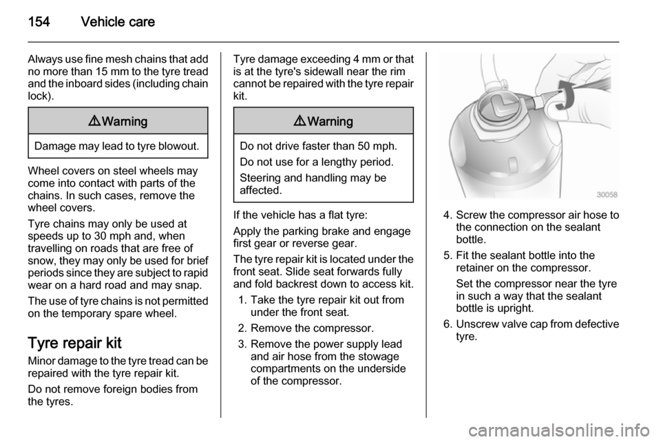
Tyre chains are only permitted on the
drive wheels.
On vehicles with twin rear wheels,
tyre chains are only permitted on the
outer wheels.
Page 156 of 201
154Vehicle care
Always use fine mesh chains that addno more than 15 mm to the tyre tread
and the inboard sides (including chain
lock).9 Warning
Damage may lead to tyre blowout.
Wheel covers on steel wheels may
come into contact with parts of the
chains. In such cases, remove the
wheel covers.
Tyre chains may only be used at
speeds up to 30 mph and, when
travelling on roads that are free of
snow, they may only be used for brief
periods since they are subject to rapid wear on a hard road and may snap.
The use of tyre chains is not permitted on the temporary spare wheel.
Tyre repair kit
Minor damage to the tyre tread can be
repaired with the tyre repair kit.
Do not remove foreign bodies from
the tyres.
Tyre damage exceeding 4 mm or that
is at the tyre's sidewall near the rim
cannot be repaired with the tyre repair kit.9 Warning
Do not drive faster than 50 mph.
Do not use for a lengthy period.
Steering and handling may be
affected.
If the vehicle has a flat tyre:
Apply the parking brake and engage
first gear or reverse gear.
The tyre repair kit is located under the
front seat. Slide seat forwards fully
and fold backrest down to access kit.
1. Take the tyre repair kit out from under the front seat.
2. Remove the compressor.
3. Remove the power supply lead and air hose from the stowage
compartments on the underside
of the compressor.4. Screw the compressor air hose to
the connection on the sealant
bottle.
5. Fit the sealant bottle into the retainer on the compressor.
Set the compressor near the tyre
in such a way that the sealant
bottle is upright.
6. Unscrew valve cap from defective
tyre.
Page 157 of 201
Vehicle care155
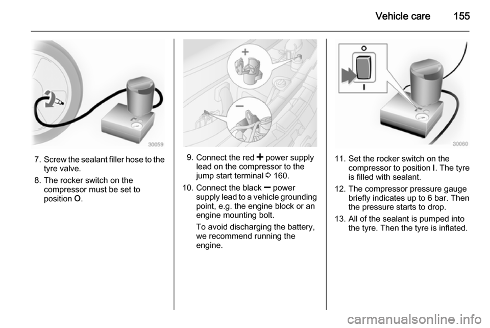
7.Screw the sealant filler hose to the
tyre valve.
8. The rocker switch on the compressor must be set to
position O.9.
Connect the red < power supply
lead on the compressor to the
jump start terminal 3 160.
10. Connect the black ] power
supply lead to a vehicle grounding
point, e.g. the engine block or an
engine mounting bolt.
To avoid discharging the battery,
we recommend running the
engine.11. Set the rocker switch on the compressor to position I. The tyre
is filled with sealant.
12. The compressor pressure gauge briefly indicates up to 6 bar. Then
the pressure starts to drop.
13. All of the sealant is pumped into the tyre. Then the tyre is inflated.
Page 158 of 201
156Vehicle care
14. The prescribed tyre pressureshould be obtained within
10 minutes. Tyre pressure
3 189 . When the correct pressure
is obtained, turn off the
compressor by setting rocker
switch to position O.
If the prescribed tyre pressure is
not obtained within 10 minutes,
remove the tyre repair kit. Move
the vehicle one tyre rotation
(approx. 2 metres). Reattach the
tyre repair kit and continue the
filling procedure for 10 minutes. If
the prescribed tyre pressure is still not obtained, the tyre is too badly
damaged. Seek the assistance of
a workshop.
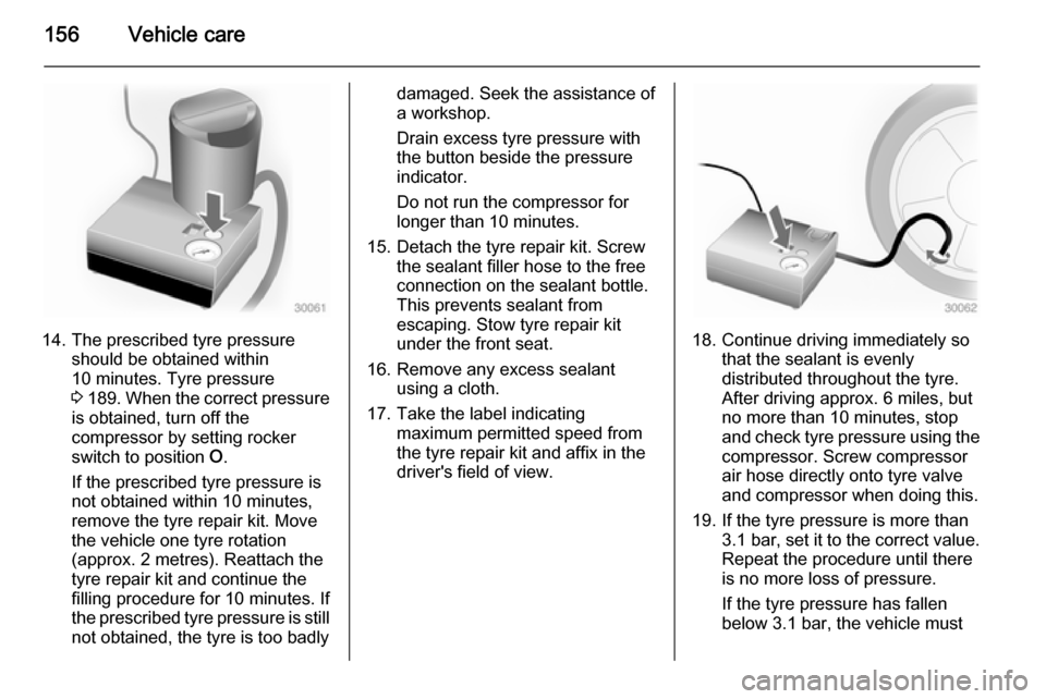
Drain excess tyre pressure with
the button beside the pressure
indicator.
Do not run the compressor for
longer than 10 minutes.
15. Detach the tyre repair kit. Screw the sealant filler hose to the free
connection on the sealant bottle.
This prevents sealant from
escaping. Stow tyre repair kit
under the front seat.
16. Remove any excess sealant using a cloth.
17. Take the label indicating maximum permitted speed from
the tyre repair kit and affix in the
driver's field of view.
18. Continue driving immediately so that the sealant is evenly
distributed throughout the tyre.
After driving approx. 6 miles, but
no more than 10 minutes, stop
and check tyre pressure using the
compressor. Screw compressor
air hose directly onto tyre valve
and compressor when doing this.
19. If the tyre pressure is more than 3.1 bar , set it to the correct value.
Repeat the procedure until there
is no more loss of pressure.
If the tyre pressure has fallen
below 3.1 bar, the vehicle must
Page 159 of 201

Vehicle care157
not be driven. Seek theassistance of a workshop.
20. Stow tyre repair kit under the front
seat.
Notice
The driving characteristics of the repaired tyre are severely affected, therefore have this tyre replaced.
If unusual noise is heard or the
compressor becomes hot, turn
compressor off for at least
30 minutes.
The built-in safety valve opens at a
pressure of 7 bar (102 psi).
Note the expiry date of the kit. After
this date its sealing capability is no
longer guaranteed. Pay attention to
storage information on sealant
bottle.
Replace the used sealant bottle. Dispose of the bottle as prescribed
by applicable laws.
The compressor and sealant can be used from approx. -30 °C.
The adapters supplied can be used
to pump up other items e.g.
footballs, air mattresses, inflatabledinghies etc. They are located on the underside of the compressor. To
remove, screw on compressor air hose and withdraw adapter.
Wheel changing Some vehicles are equipped with a
tyre repair kit instead of a spare wheel 3 154.
Make the following preparations and
observe the following information:
■ Park the vehicle on a level, firm and
non-slippery surface. The frontwheels must be in the straight-ahead position.
■ Apply the parking brake and engage first gear or reverse gear.
■ Switch off the air suspension system 3 110.
■ Remove the spare wheel 3 159.
■ Never change more than one wheel
at a time.
■ Use the jack only to change wheels
in case of puncture, not for
seasonal winter or summer tyre
change.■ If the ground on which the vehicle is standing is soft, a solid board
(max. 1 cm thick) should be placed
under the jack.
■ No people or animals may be in the
vehicle when it is jacked-up.
■ Never crawl under a jacked-up vehicle.
■ Do not start the engine when the vehicle is raised on the jack.
■ Clean wheel bolts/nuts and their threads before mounting the wheel.9 Warning
Do not grease wheel bolt, wheel
nut and wheel nut cone.
1. Remove the wheel cover using the hook supplied. Vehicle tools
3 150.
2. Install the wheel wrench ensuring that it locates securely and loosen
each wheel bolt/nut by half a turn.
Page 160 of 201
158Vehicle care
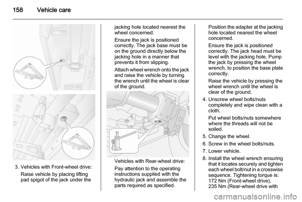
3. Vehicles with Front-wheel drive:Raise vehicle by placing lifting
pad spigot of the jack under the
jacking hole located nearest the
wheel concerned.
Ensure the jack is positioned
correctly. The jack base must be
on the ground directly below the
jacking hole in a manner that
prevents it from slipping.
Attach wheel wrench onto the jack
and raise the vehicle by turning
the wrench until the wheel is clear of the ground.
Vehicles with Rear-wheel drive:
Pay attention to the operating
instructions supplied with the
hydraulic jack and assemble the
parts required as specified.
Position the adapter at the jacking
hole located nearest the wheel
concerned.
Ensure the jack is positioned
correctly. The jack head must be
level with the jacking hole. Pump
the jack by pressing the wheel
wrench, to position the base plate
correctly.
Raise the vehicle by pressing the wheel wrench until the wheel is
clear of the ground.
4. Unscrew wheel bolts/nuts completely and wipe clean with a
cloth.
Put wheel bolts/nuts somewhere
where the threads will not be
soiled.
5. Change the wheel.
6. Screw in the wheel bolts/nuts.
7. Lower vehicle.
8. Install the wheel wrench ensuring that it locates securely and tighten
each wheel bolt/nut in a crosswise sequence. Tightening torque is:
172 Nm (Front-wheel drive),
235 Nm (Rear-wheel drive with