VAUXHALL MOVANO_B 2015 Owner's Manual
Manufacturer: VAUXHALL, Model Year: 2015, Model line: MOVANO_B, Model: VAUXHALL MOVANO_B 2015Pages: 209, PDF Size: 4.92 MB
Page 151 of 209
Vehicle care149
7. Push bulb into socket slightly,rotate anti-clockwise, remove and
renew bulb.
Turn signal light ( 1)
Tail and brake light ( 2)
Reverse light ( 3)
Rear fog light, may be on one side only ( 4)
8. Replace bulb holder in lamp assembly.
9. Replace the three screws on the rear of the lamp assembly.
10. Reattach wiring connector to lamp
assembly.
11. Replace lamp assembly from the outer side into original position,
ensuring that it is seated correctly.
12. Replace the two nuts onto the locating pins on the rear of the
lamp assembly.
13. Install the upper and lower trim panels to the rear pillar.Side turn signal lights
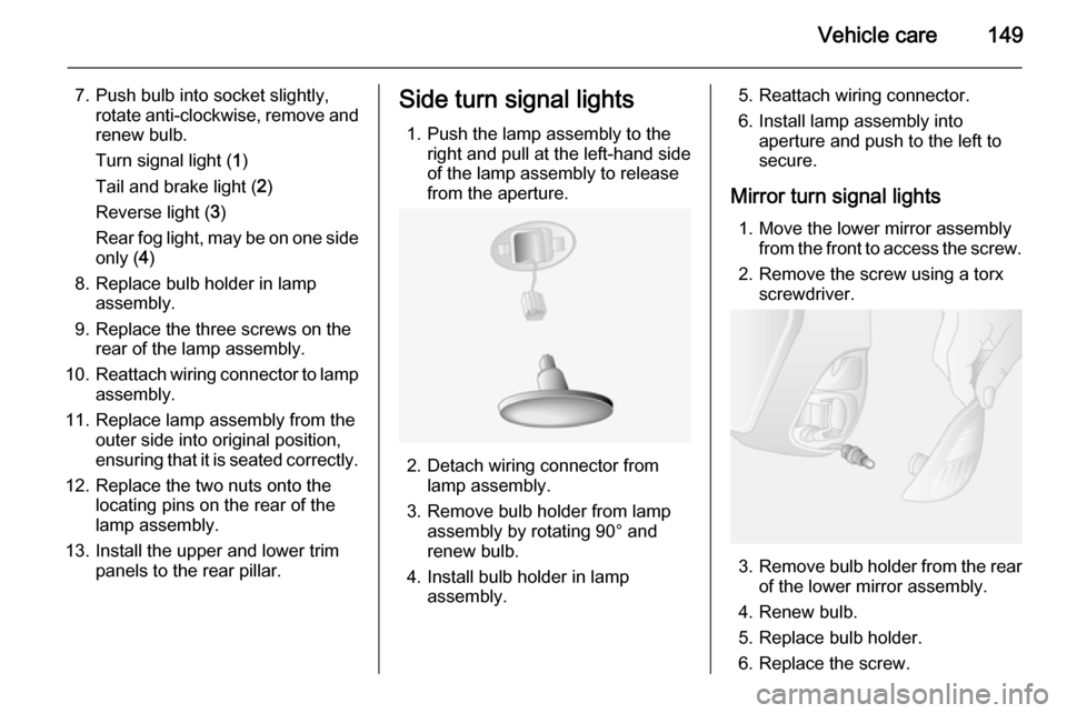
1. Push the lamp assembly to the right and pull at the left-hand side
of the lamp assembly to release
from the aperture.
2. Detach wiring connector from lamp assembly.
3. Remove bulb holder from lamp assembly by rotating 90° and
renew bulb.
4. Install bulb holder in lamp assembly.
5. Reattach wiring connector.
6. Install lamp assembly into aperture and push to the left to
secure.
Mirror turn signal lights 1. Move the lower mirror assembly from the front to access the screw.
2. Remove the screw using a torx screwdriver.
3. Remove bulb holder from the rear
of the lower mirror assembly.
4. Renew bulb.
5. Replace bulb holder.
6. Replace the screw.
Page 152 of 209
150Vehicle careCentre high-mounted
brake light
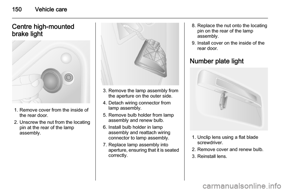
1. Remove cover from the inside of the rear door.
2. Unscrew the nut from the locating
pin at the rear of the lamp
assembly.
3. Remove the lamp assembly from the aperture on the outer side.
4. Detach wiring connector from lamp assembly.
5. Remove bulb holder from lamp assembly and renew bulb.
6. Install bulb holder in lamp assembly and reattach wiring
connector to lamp assembly.
7. Replace lamp assembly into aperture, ensuring that it is seated
correctly.
8. Replace the nut onto the locating pin on the rear of the lamp
assembly.
9. Install cover on the inside of the rear door.
Number plate light
1. Unclip lens using a flat blade screwdriver.
2. Remove cover and renew bulb.
3. Reinstall lens.
Page 153 of 209
Vehicle care151Interior lightsFront courtesy light
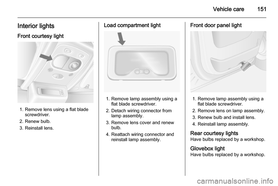
1. Remove lens using a flat blade screwdriver.
2. Renew bulb.
3. Reinstall lens.
Load compartment light
1. Remove lamp assembly using a flat blade screwdriver.
2. Detach wiring connector from lamp assembly.
3. Remove lens cover and renew bulb.
4. Reattach wiring connector and reinstall lamp assembly.
Front door panel light
1. Remove lamp assembly using aflat blade screwdriver.
2. Remove lens on lamp assembly.
3. Renew bulb and install lens. 4. Reinstall lamp assembly.
Rear courtesy lights
Have bulbs replaced by a workshop.
Glovebox light
Have bulbs replaced by a workshop.
Page 154 of 209
152Vehicle careInstrument panel
illumination Have bulbs replaced by a workshop.Electrical system
Fuses
Data on the replacement fuse must match the data on the defective fuse.
There are two fuse boxes in the
vehicle:
■ on the left-hand side of the instrument panel, behind the trim
panel.
■ in the engine compartment located below the coolant expansion tank.
Before replacing a fuse, turn off the respective switch and the ignition.
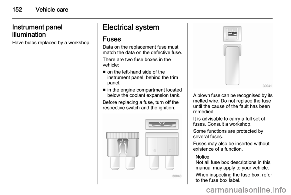
A blown fuse can be recognised by its melted wire. Do not replace the fuse
until the cause of the fault has been
remedied.
It is advisable to carry a full set of
fuses. Consult a workshop.
Some functions are protected by
several fuses.
Fuses may also be inserted without
existence of a function.
Notice
Not all fuse box descriptions in this
manual may apply to your vehicle.
When inspecting the fuse box, refer to the fuse box label.
Page 155 of 209
Vehicle care153
Fuse extractor
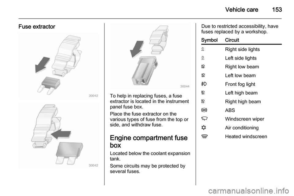
To help in replacing fuses, a fuse
extractor is located in the instrument
panel fuse box.
Place the fuse extractor on the
various types of fuse from the top or
side, and withdraw fuse.
Engine compartment fusebox
Located below the coolant expansion tank.
Some circuits may be protected by
several fuses.
Due to restricted accessibility, have
fuses replaced by a workshop.SymbolCircuitSRight side lightsTLeft side lightsWRight low beamaLeft low beam>Front fog lightLLeft high beamNRight high beamuABSKWindscreen wipernAir conditioningVHeated windscreen
Page 156 of 209
154Vehicle careInstrument panel fuse box
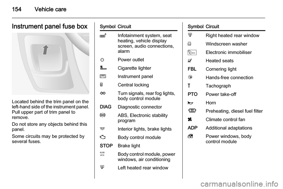
Located behind the trim panel on the
left-hand side of the instrument panel. Pull upper part of trim panel to
remove.
Do not store any objects behind this
panel.
Some circuits may be protected by
several fuses.
SymbolCircuitZInfotainment system, seat
heating, vehicle display
screen, audio connections,
alarm?Power outletÌCigarette lightereInstrument panelUCentral lockingOTurn signals, rear fog lights,
body control moduleDIAGDiagnostic connectoruABS, Electronic stability
programdInterior lights, brake lightsZBody control moduleSTOPBrake lightIBody control module, power windows, air conditioningmLeft heated rear windowSymbolCircuitnRight heated rear windowRWindscreen washerMElectronic immobiliserUHeated seatsFBLCornering lightlHands-free connection&TachographPTOPower take-offjHornÍPreheating, diesel fuel filterxClimate control fanADPAdditional adaptations,Power windows, body
control module
Page 157 of 209
Vehicle care155Vehicle tools
Tools
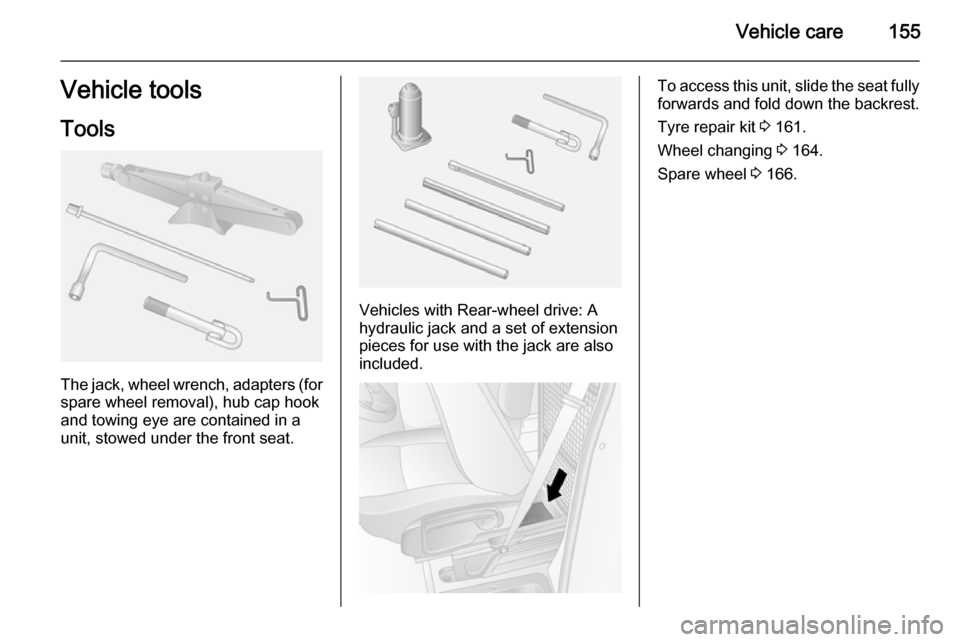
The jack, wheel wrench, adapters (for
spare wheel removal), hub cap hook
and towing eye are contained in a
unit, stowed under the front seat.
Vehicles with Rear-wheel drive: A hydraulic jack and a set of extension
pieces for use with the jack are also
included.
To access this unit, slide the seat fully forwards and fold down the backrest.
Tyre repair kit 3 161.
Wheel changing 3 164.
Spare wheel 3 166.
Page 158 of 209

156Vehicle careWheels and tyres
Tyre condition, wheel condition
Drive over edges slowly and at right
angles if possible. Driving over sharp
edges can cause tyre and wheel
damage. Do not trap tyres on the kerb when parking.
Regularly check the wheels for
damage. Seek the assistance of a
workshop in the event of damage or
unusual wear.
Tyres Factory-fitted tyres are matched to
the chassis and offer optimum driving
comfort and safety.
Winter tyres Winter tyres improve driving safety attemperatures below 7 °C and shouldtherefore be fitted on all wheels.
In accordance with country-specific
regulations, affix the maximum speed
sticker in the driver's field of view.Tyre designations
E.g. 215/65 R 16 C 109 R215=Tyre width, mm65=Cross-section ratio (tyre height
to tyre width), %R=Belt type:RadialRF=Type:RunFlat16=Wheel diameter, inchesC=Cargo or commercial use88=Load index e.g. 109 is
equivalent to approx. 1030 kgR=Speed code letter
Speed code letter:
Q=up to 100 mphS=up to 112 mphT=up to 118 mphH=up to 130 mphV=up to 150 mphW=up to 168 mph
Tyre pressure
Check the pressure of cold tyres at
least every 14 days and before any
long journey. Do not forget the spare
wheel. This also applies to vehicles
with tyre pressure monitoring system.
Tyre pressures 3 198. Always inflate
tyres to the pressures shown on the
label on the driver's door frame.
The tyre pressure data refers to cold
tyres. It applies to summer and winter tyres.
Always inflate the spare tyre to the
pressure specified for full load.
Incorrect tyre pressures will impair
safety, vehicle handling, comfort and
fuel economy and will increase tyre
wear.
Tyre pressures differ depending on
various options. For the correct tyre
pressure value, follow the procedure
below:
1. Identify the engine identifier code.
Engine data 3 182.
2. Identify the respective tyre.
The tyre pressure tables show all possible tyre combinations 3 198.
For the tyres approved for your
vehicle, refer to the EEC Certificate of
Conformity provided with your vehicle or other national registration
documents.
Page 159 of 209
Vehicle care157
The driver is responsible for correct
adjustment of tyre pressure.9 Warning
If the pressure is too low, this can
result in considerable tyre warm-
up and internal damage, leading to tread separation and even to tyre
blow-out at high speeds.
Rear-wheel drive, with twin rear
wheels When inflating the outer tyre, the
inflation tube should be passed
between the two wheels.
Tyre pressure monitoring
system
The Tyre Pressure Monitoring
System (TPMS) uses radio and
sensor technology to check tyre
pressure levels.
Caution
Tyre pressure monitoring system
warns only about low tyre pressure condition and does not replace
regular tyre maintenance by the
driver.
All wheels must be equipped with pressure sensors and the tyres must
have the prescribed pressure.
Notice
In countries where the tyre pressure
monitoring system is legally
required, the use of wheels without
pressure sensors will invalidate the
vehicle type approval.
The TPMS sensors monitor the air
pressure in the tyres and transmit tyre pressure readings to a receiver
located in the vehicle.
Each tyre, including the spare, should
be checked monthly when cold and
inflated to the inflation pressure
recommended on the tyre pressure
label.
Tyre pressures in display
The current tyre pressures can be
shown in the Driver Information
Centre 3 84.
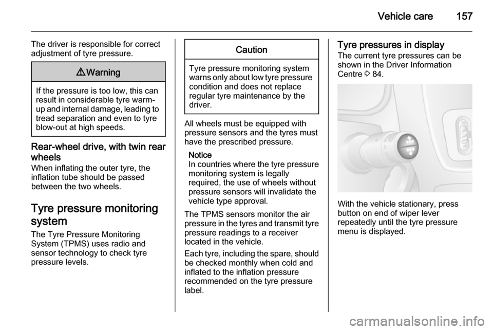
With the vehicle stationary, press
button on end of wiper lever
repeatedly until the tyre pressure
menu is displayed.
Page 160 of 209
158Vehicle care
Low tyre pressure condition
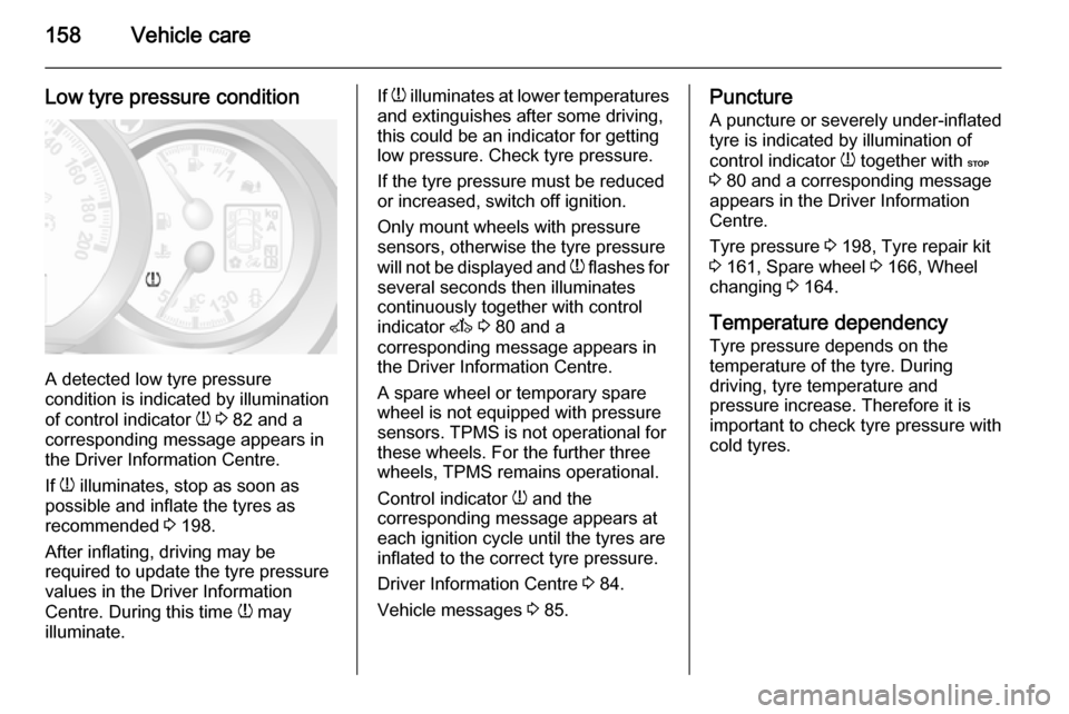
A detected low tyre pressure
condition is indicated by illumination
of control indicator w 3 82 and a
corresponding message appears in
the Driver Information Centre.
If w illuminates, stop as soon as
possible and inflate the tyres as
recommended 3 198.
After inflating, driving may be
required to update the tyre pressure
values in the Driver Information
Centre. During this time w may
illuminate.
If w illuminates at lower temperatures
and extinguishes after some driving,
this could be an indicator for getting low pressure. Check tyre pressure.
If the tyre pressure must be reduced
or increased, switch off ignition.
Only mount wheels with pressure
sensors, otherwise the tyre pressure
will not be displayed and w flashes for
several seconds then illuminates continuously together with control
indicator A 3 80 and a
corresponding message appears in
the Driver Information Centre.
A spare wheel or temporary spare
wheel is not equipped with pressure
sensors. TPMS is not operational for these wheels. For the further three
wheels, TPMS remains operational.
Control indicator w and the
corresponding message appears at
each ignition cycle until the tyres are
inflated to the correct tyre pressure.
Driver Information Centre 3 84.
Vehicle messages 3 85.Puncture
A puncture or severely under-inflated
tyre is indicated by illumination of
control indicator w together with C
3 80 and a corresponding message
appears in the Driver Information
Centre.
Tyre pressure 3 198, Tyre repair kit
3 161, Spare wheel 3 166, Wheel
changing 3 164.
Temperature dependency Tyre pressure depends on the
temperature of the tyre. During
driving, tyre temperature and
pressure increase. Therefore it is important to check tyre pressure with
cold tyres.