engine VAUXHALL VIVARO 2015.5 Workshop Manual
[x] Cancel search | Manufacturer: VAUXHALL, Model Year: 2015.5, Model line: VIVARO, Model: VAUXHALL VIVARO 2015.5Pages: 203, PDF Size: 4.54 MB
Page 140 of 203
138Vehicle careBonnetOpening
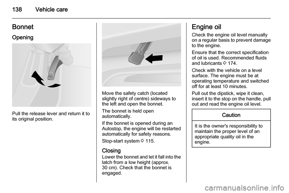
Pull the release lever and return it to
its original position.
Move the safety catch (located
slightly right of centre) sideways to
the left and open the bonnet.
The bonnet is held open
automatically.
If the bonnet is opened during an
Autostop, the engine will be restarted automatically for safety reasons.
Stop-start system 3 115.
Closing Lower the bonnet and let it fall into the
latch from a low height (approx.
30 cm). Check that the bonnet is
engaged.
Engine oil
Check the engine oil level manually
on a regular basis to prevent damage
to the engine.
Ensure that the correct specification
of oil is used. Recommended fluids
and lubricants 3 174.
Check with the vehicle on a level
surface. The engine must be at
operating temperature and switched
off for at least 10 minutes.
Pull out the dipstick, wipe it clean,
insert it to the stop on the handle, pull
out and read the engine oil level.Caution
It is the owner's responsibility to
maintain the proper level of an
appropriate quality oil in the
engine.
Page 141 of 203
Vehicle care139
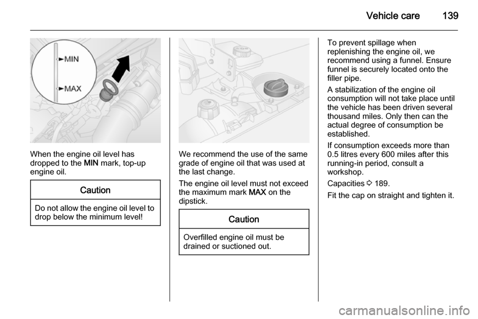
When the engine oil level has
dropped to the MIN mark, top-up
engine oil.
Caution
Do not allow the engine oil level to drop below the minimum level!
We recommend the use of the same
grade of engine oil that was used at
the last change.
The engine oil level must not exceed the maximum mark MAX on the
dipstick.
Caution
Overfilled engine oil must be
drained or suctioned out.
To prevent spillage when
replenishing the engine oil, we
recommend using a funnel. Ensure funnel is securely located onto the
filler pipe.
A stabilization of the engine oil
consumption will not take place until
the vehicle has been driven several
thousand miles. Only then can the
actual degree of consumption be
established.
If consumption exceeds more than
0.5 litres every 600 miles after this
running-in period, consult a
workshop.
Capacities 3 189.
Fit the cap on straight and tighten it.
Page 142 of 203

140Vehicle careEngine air filterEngine air flow indicator
On certain models, an indicator is
located in the engine induction
system and indicates if the air-intake
to the engine is restricted.
Clear=No restrictionRed tell-tale=Restricted
If the red tell-tale is displayed when
the engine is running, consult a
workshop.
Engine coolant
The coolant provides freeze
protection down to approx. -28 °C.Caution
Only use approved antifreeze.
Coolant level
Caution
Too low a coolant level can cause engine damage.
If the cooling system is cold, the
coolant level should be just above the
MINI mark. Top up if the level is low.9Warning
Allow the engine to cool before
opening the cap. Carefully open
the cap, relieving the pressure
slowly.
Top up with antifreeze. If no
antifreeze is available, use clean tap
water or distilled water. Install the cap
tightly. Have the antifreeze
concentration checked and have the
cause of the coolant loss remedied by a workshop.
If a substantial amount of coolant is
required, it will be necessary to bleed
any trapped air from the cooling
system. Seek the assistance of a
workshop.
If the coolant temperature is too high, control indicator W 3 86 illuminates
red in the instrument cluster, together
with C 3 84. Consult a workshop if
coolant level is sufficient.
Page 144 of 203
142Vehicle careBrakesA squealing noise indicates that the
brake lining is at its minimum
thickness. Continued driving is
possible but have the brake lining
replaced as soon as possible.
Once new brake linings are installed,
do not brake unnecessarily hard for
the first few journeys.
Brake fluid9 Warning
Brake fluid is poisonous and
corrosive. Avoid contact with eyes, skin, fabrics and painted surfaces.
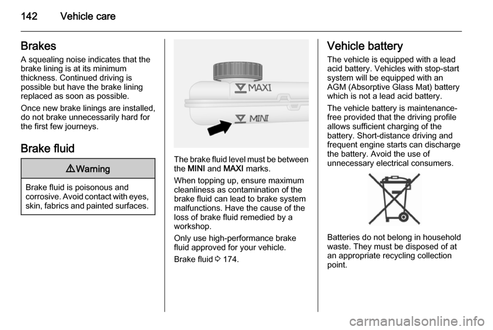
The brake fluid level must be betweenthe MINI and MAXI marks.
When topping up, ensure maximum cleanliness as contamination of the
brake fluid can lead to brake system
malfunctions. Have the cause of the
loss of brake fluid remedied by a
workshop.
Only use high-performance brake
fluid approved for your vehicle.
Brake fluid 3 174.
Vehicle battery
The vehicle is equipped with a lead
acid battery. Vehicles with stop-start
system will be equipped with an
AGM (Absorptive Glass Mat) battery
which is not a lead acid battery.
The vehicle battery is maintenance-
free provided that the driving profile
allows sufficient charging of the
battery. Short-distance driving and
frequent engine starts can discharge
the battery. Avoid the use of
unnecessary electrical consumers.
Batteries do not belong in household
waste. They must be disposed of at
an appropriate recycling collection
point.
Page 146 of 203
144Vehicle care
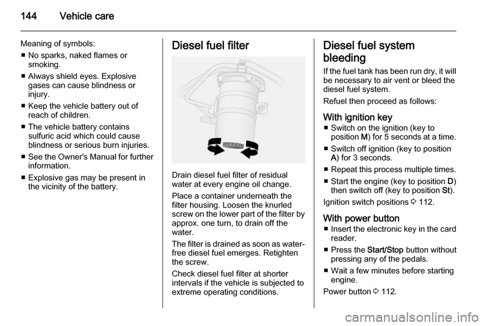
Meaning of symbols:■ No sparks, naked flames or smoking.
■ Always shield eyes. Explosive gases can cause blindness or
injury.
■ Keep the vehicle battery out of reach of children.
■ The vehicle battery contains sulfuric acid which could cause
blindness or serious burn injuries.
■ See the Owner's Manual for further
information.
■ Explosive gas may be present in the vicinity of the battery.Diesel fuel filter
Drain diesel fuel filter of residual
water at every engine oil change.
Place a container underneath the
filter housing. Loosen the knurled
screw on the lower part of the filter by approx. one turn, to drain off the
water.
The filter is drained as soon as water-
free diesel fuel emerges. Retighten
the screw.
Check diesel fuel filter at shorter
intervals if the vehicle is subjected to
extreme operating conditions.
Diesel fuel system
bleeding
If the fuel tank has been run dry, it will
be necessary to air vent or bleed the
diesel fuel system.
Refuel then proceed as follows:
With ignition key ■ Switch on the ignition (key to position M) for 5 seconds at a time.
■ Switch off ignition (key to position A) for 3 seconds.
■ Repeat this process multiple times.
■ Start the engine (key to position D)
then switch off (key to position St).
Ignition switch positions 3 112.
With power button ■ Insert the electronic key in the card
reader.
■ Press the Start/Stop button without
pressing any of the pedals.
■ Wait a few minutes before starting engine.
Power button 3 112.
Page 147 of 203
Vehicle care145
If the engine fails to start, seek the
assistance of a workshop.
Starting the engine 3 114.
Wiper blade replacement Wiper blades on the windscreen
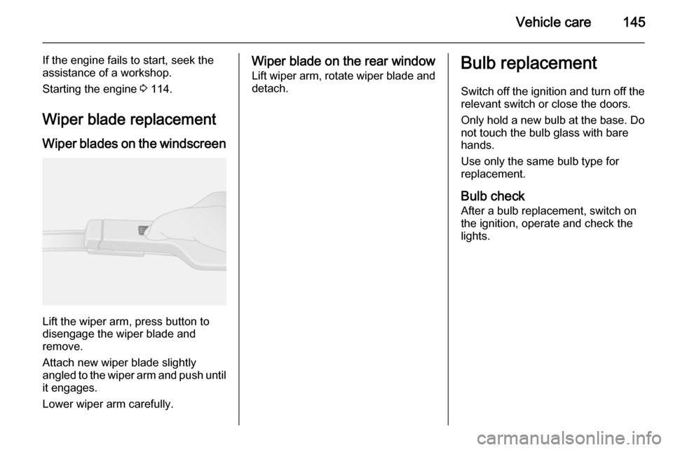
Lift the wiper arm, press button to
disengage the wiper blade and
remove.
Attach new wiper blade slightly
angled to the wiper arm and push until
it engages.
Lower wiper arm carefully.
Wiper blade on the rear window Lift wiper arm, rotate wiper blade and
detach.Bulb replacement
Switch off the ignition and turn off the
relevant switch or close the doors.
Only hold a new bulb at the base. Do not touch the bulb glass with bare
hands.
Use only the same bulb type for
replacement.
Bulb check
After a bulb replacement, switch on
the ignition, operate and check the
lights.
Page 159 of 203
Vehicle care157
Tyre pressures 3 190. Always inflate
tyres to the pressures shown on the label on the driver's door frame.
The tyre pressure data refers to cold
tyres. It applies to summer and winter tyres.
Always inflate the spare tyre to the
pressure specified for full load.
Incorrect tyre pressures will impair
safety, vehicle handling, comfort and
fuel economy and will increase tyre
wear.
Tyre pressures differ depending on
various options. For the correct tyre
pressure value, follow the procedure
below:
1. Identify the engine identifier code.
Engine data 3 180.
2. Identify the respective tyre.
The tyre pressure tables show all
possible tyre combinations 3 190.
For the tyres approved for your
vehicle, refer to the EEC Certificate of
Conformity provided with your vehicle
or other national registration
documents.The driver is responsible for correct
adjustment of tyre pressure.9 Warning
If the pressure is too low, this can
result in considerable tyre warm-
up and internal damage, leading to tread separation and even to tyre
blow-out at high speeds.
Tyre pressure monitoring
system
The Tyre Pressure Monitoring
System (TPMS) uses radio and
sensor technology to check tyre
pressure levels.
Caution
Tyre pressure monitoring system
warns only about low tyre pressure condition and does not replace
regular tyre maintenance by the
driver.
All wheels must be equipped with pressure sensors and the tyres must
have the prescribed pressure.
Notice
In countries where the tyre pressure
monitoring system is legally
required, the use of wheels without
pressure sensors will invalidate the
vehicle type approval.
The TPMS sensors monitor the air
pressure in the tyres and transmit tyre pressure readings to a receiver
located in the vehicle.
Tyre pressures in display The current tyre pressures can be
shown in the Driver Information
Centre 3 88.
Page 161 of 203
Vehicle care159
Puncture
A puncture or severely under-inflated
tyre is indicated by illumination of
control indicator w together with C
3 84 and a corresponding message
appears in the Driver Information
Centre. Stop vehicle and switch off
engine.
Tyre pressure 3 190, Tyre repair kit
3 161, Spare wheel 3 165, Wheel
changing 3 164.
Temperature dependency Tyre pressure depends on the
temperature of the tyre. During
driving, tyre temperature and
pressure increase.
The tyre pressure value displayed in
the Driver Information Centre shows
the actual tyre pressure. Therefore it
is important to check tyre pressure
with cold tyres.Relearn function
After changing the wheels, TPMS
needs to recalculate.
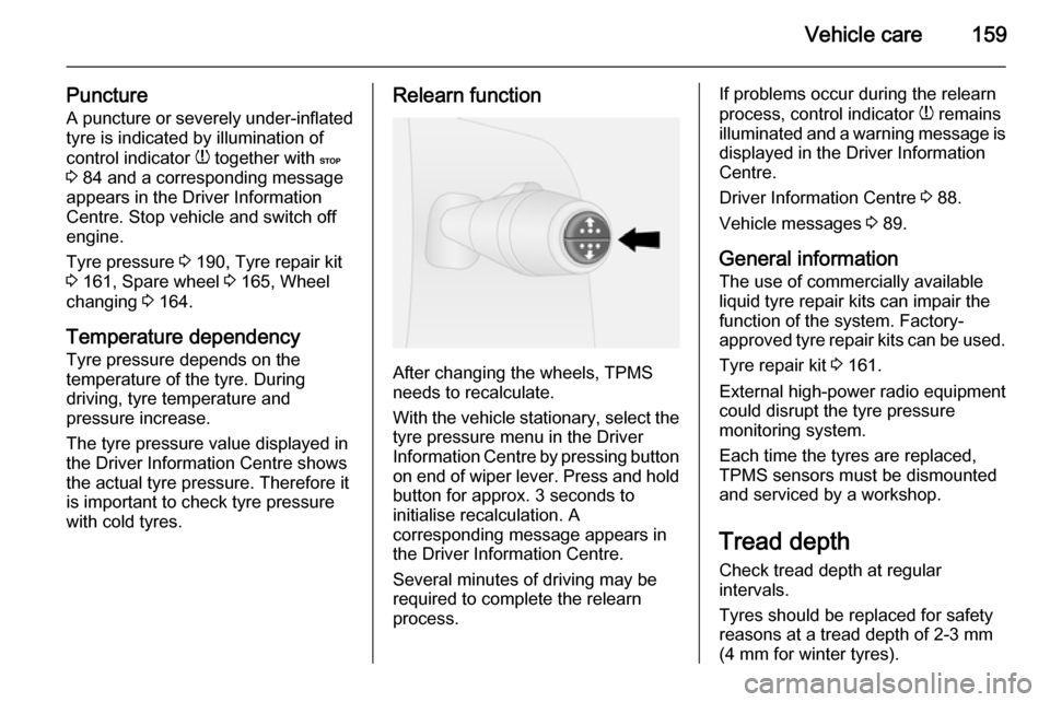
With the vehicle stationary, select the tyre pressure menu in the Driver
Information Centre by pressing button
on end of wiper lever. Press and hold button for approx. 3 seconds to
initialise recalculation. A
corresponding message appears in
the Driver Information Centre.
Several minutes of driving may be
required to complete the relearn
process.
If problems occur during the relearn
process, control indicator w remains
illuminated and a warning message is displayed in the Driver Information
Centre.
Driver Information Centre 3 88.
Vehicle messages 3 89.
General information
The use of commercially available
liquid tyre repair kits can impair the
function of the system. Factory-
approved tyre repair kits can be used.
Tyre repair kit 3 161.
External high-power radio equipment
could disrupt the tyre pressure
monitoring system.
Each time the tyres are replaced,
TPMS sensors must be dismounted
and serviced by a workshop.
Tread depth
Check tread depth at regular
intervals.
Tyres should be replaced for safety
reasons at a tread depth of 2-3 mm
(4 mm for winter tyres).
Page 164 of 203
162Vehicle care
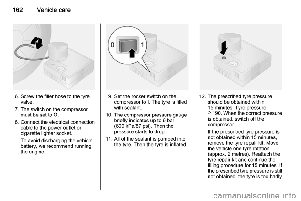
6. Screw the filler hose to the tyrevalve.
7. The switch on the compressor must be set to O.
8. Connect the electrical connection cable to the power outlet or
cigarette lighter socket.
To avoid discharging the vehicle
battery, we recommend running
the engine.9. Set the rocker switch on the compressor to I. The tyre is filled
with sealant.
10. The compressor pressure gauge briefly indicates up to 6 bar(600 kPa/87 psi). Then the
pressure starts to drop.
11. All of the sealant is pumped into the tyre. Then the tyre is inflated.12. The prescribed tyre pressureshould be obtained within
15 minutes. Tyre pressure
3 190 . When the correct pressure
is obtained, switch off the
compressor.
If the prescribed tyre pressure is
not obtained within 15 minutes,
remove the tyre repair kit. Move
the vehicle one tyre rotation
(approx. 2 metres). Reattach the
tyre repair kit and continue the
filling procedure for 15 minutes. If
the prescribed tyre pressure is still not obtained, the tyre is too badly
Page 166 of 203

164Vehicle care
Replace the used sealant bottle.Dispose of the sealant bottle as
prescribed by applicable laws.
Wheel changing
Some vehicles are equipped with a
tyre repair kit instead of a spare wheel 3 161.
Make the following preparations and
observe the following information:
■ Park the vehicle on a level, firm and
non-slippery surface. The front wheels must be in the straight-
ahead position.
■ Apply the parking brake and engage first gear or reverse gear.
■ Remove the spare wheel 3 165.
■ Never change more than one wheel
at a time.
■ Use the jack only to change wheels
in case of puncture, not for a
seasonal winter or summer tyre
change.
■ If the ground on which the vehicle is standing is soft, a solid board
(max. 1 cm thick) should be placed
under the jack.■ Take heavy objects out of the vehicle before jacking up.
■ No people or animals may be in the
vehicle when it is jacked-up.
■ Never crawl under a jacked-up vehicle.
■ Do not start the engine when the vehicle is raised on the jack.
1. Remove the wheel cover (using the hook supplied). Vehicle tools
3 155.
2. Loosen each of the wheel bolts by
half a turn using the wheel
wrench. Ensure the wrench
locates securely. The wrench
should turn anticlockwise to
loosen the bolts. Invert the wrench if necessary.
3. Place lifting pad spigot of the jack
under the jacking hole located
nearest the wheel concerned.
Ensure the jack is positioned
correctly. The jack base must be
on the ground directly below the
jacking hole in a manner that
prevents it from slipping.
4. Install wrench onto the jack and raise the vehicle by turning the
wrench until the wheel is clear of
the ground.