check engine light VOLKSWAGEN CORRADO 1990 Repair Manual
[x] Cancel search | Manufacturer: VOLKSWAGEN, Model Year: 1990, Model line: CORRADO, Model: VOLKSWAGEN CORRADO 1990Pages: 906, PDF Size: 6.56 MB
Page 2 of 906

J - PIN VOLTAGE CHARTSK - SENSOR RANGE CHARTSL - WIRING DIAGRAMSM - VACUUM DIAGRAMSMAINTENANCE INFORMATIONMAINTENANCE REMINDER LIGHT RESET PROCEDURESMETRIC CONVERSIONSMETRIC CONVERSIONSMIRRORS - POWERN - REMOVE/INSTALL/OVERHAULP - EGR FUNCTION TESTINGPOSSIBLE ENGINE STALL DUE TO FUEL RESTRICTIONPRE-ALIGNMENT CHECKSSCHEDULED SERVICESSERVICE INDICATOR & WARNING LIGHTSSTARTER - BOSCHSTEERING COLUMNSTEERING COLUMN SWITCHESSTEERING SYSTEM - POWERSUSPENSION - FRONTSUSPENSION - REARTRANSMISSION REMOVAL & INSTALLATION - A/TTRANSMISSION SERVICING - A/TTRANSMISSION SERVICING - M/TTROUBLE SHOOTING - BASIC PROCEDURESWAVEFORMS - INJECTOR PATTERN TUTORIALWHEEL ALIGNMENT SPECIFICATIONS & PROCEDURESWHEEL ALIGNMENT THEORY/OPERATIONWIPER/WASHER SYSTEMWIRING DIAGRAM SYMBOLSWIRING DIAGRAMS
Page 102 of 906

* ENGINE SYSTEMS UNIFORM INSPECTION GUIDELINES *
Article Text (p. 5)
1990 Volkswagen Corrado
For Volkswagen Technical Site: http://vw.belcom.ru
Copyright © 1998 Mitchell Repair Information Company, LLC
Thursday, March 23, 2000 09:31PM
threads in oil pan for damage.ÄÄÄÄÄÄÄÄÄÄÄÄÄÄÄÄÄÄÄÄÄÄÄÄÄÄÄÄÄÄÄÄÄÄÄÄÄÄÄÄÄÄÄÄÄÄÄÄÄÄÄÄÄÄÄÄÄÄÄÄÄÄÄÄÄÄÄÄÄÄENGINE OIL WARNING LIGHTS
ÄÄÄÄÄÄÄÄÄÄÄÄÄÄÄÄÄÄÄÄÄÄÄÄÄÄÄÄÄÄÄÂÄÄÄÄÄÄÄÄÄÄÄÄÄÄÄÄÄÄÄÄÄÄÄÄÄÄÄÄÄÄÄÄÄÄÄÄÄÄCondition
³ Procedure
ÄÄÄÄÄÄÄÄÄÄÄÄÄÄÄÄÄÄÄÄÄÄÄÄÄÄÄÄÄÄÄÅÄÄÄÄÄÄÄÄÄÄÄÄÄÄÄÄÄÄÄÄÄÄÄÄÄÄÄÄÄÄÄÄÄÄÄÄÄÄLight not on during bulb check
³ Further inspection required. See
³ NOTE: below.
ÄÄÄÄÄÄÄÄÄÄÄÄÄÄÄÄÄÄÄÄÄÄÄÄÄÄÄÄÄÄÄÅÄÄÄÄÄÄÄÄÄÄÄÄÄÄÄÄÄÄÄÄÄÄÄÄÄÄÄÄÄÄÄÄÄÄÄÄÄÄLight stays on or intermittent
³ Further inspection required. See
while engine is running
³ NOTE: below.
ÄÄÄÄÄÄÄÄÄÄÄÄÄÄÄÄÄÄÄÄÄÄÄÄÄÄÄÄÄÄÄÅÄÄÄÄÄÄÄÄÄÄÄÄÄÄÄÄÄÄÄÄÄÄÄÄÄÄÄÄÄÄÄÄÄÄÄÄÄÄNOTE: Light may indicate problem with contaminated oil, level,
pressure, temperature or problem with circuit.
ÄÄÄÄÄÄÄÄÄÄÄÄÄÄÄÄÄÄÄÄÄÄÄÄÄÄÄÄÄÄÄÄÄÄÄÄÄÄÄÄÄÄÄÄÄÄÄÄÄÄÄÄÄÄÄÄÄÄÄÄÄÄÄÄÄÄÄÄÄÄENGINE OIL PRESSURE GAUGE
ÄÄÄÄÄÄÄÄÄÄÄÄÄÄÄÄÄÄÄÄÄÄÄÂÄÄÄÄÄÄÄÄÄÄÄÄÄÄÄÄÄÄÄÄÄÄÄÄÄÄÄÄÄÄÄÄÄÄÄÄÄÄÄÄÄÄÄÄÄÄCondition
³ Procedure
ÄÄÄÄÄÄÄÄÄÄÄÄÄÄÄÄÄÄÄÄÄÄÄÅÄÄÄÄÄÄÄÄÄÄÄÄÄÄÄÄÄÄÄÄÄÄÄÄÄÄÄÄÄÄÄÄÄÄÄÄÄÄÄÄÄÄÄÄÄÄInoperative
³ Further inspection required. See note.
ÄÄÄÄÄÄÄÄÄÄÄÄÄÄÄÄÄÄÄÄÄÄÄÅÄÄÄÄÄÄÄÄÄÄÄÄÄÄÄÄÄÄÄÄÄÄÄÄÄÄÄÄÄÄÄÄÄÄÄÄÄÄÄÄÄÄÄÄÄÄIndicates out of range
³ Further inspection required. See note.
ÄÄÄÄÄÄÄÄÄÄÄÄÄÄÄÄÄÄÄÄÄÄÄÁÄÄÄÄÄÄÄÄÄÄÄÄÄÄÄÄÄÄÄÄÄÄÄÄÄÄÄÄÄÄÄÄÄÄÄÄÄÄÄÄÄÄÄÄÄÄNOTE: Gauge may indicate problem with contaminated oil, level,
pressure, temperature or problem with gauge.
ÄÄÄÄÄÄÄÄÄÄÄÄÄÄÄÄÄÄÄÄÄÄÄÄÄÄÄÄÄÄÄÄÄÄÄÄÄÄÄÄÄÄÄÄÄÄÄÄÄÄÄÄÄÄÄÄÄÄÄÄÄÄÄÄÄÄÄÄÄÄOIL PRESSURE SENDING UNIT
ÄÄÄÄÄÄÄÄÄÄÄÄÄÄÄÄÄÄÄÄÄÄÄÄÄÄÄÄÄÄÄÄÄÄÄÄÂÄÄÄÄÄÄÄÄÄÄÄÄÄÄÄÄÄÄÄÄÄÄÄÄÄÄÄÄÄÄÄÄÄCondition
³ Procedure
ÄÄÄÄÄÄÄÄÄÄÄÄÄÄÄÄÄÄÄÄÄÄÄÄÄÄÄÄÄÄÄÄÄÄÄÄÅÄÄÄÄÄÄÄÄÄÄÄÄÄÄÄÄÄÄÄÄÄÄÄÄÄÄÄÄÄÄÄÄÄLeaking
³ Require replacement.
ÄÄÄÄÄÄÄÄÄÄÄÄÄÄÄÄÄÄÄÄÄÄÄÄÄÄÄÄÄÄÄÄÄÄÄÄÅÄÄÄÄÄÄÄÄÄÄÄÄÄÄÄÄÄÄÄÄÄÄÄÄÄÄÄÄÄÄÄÄÄConnector or terminal bent, broken,
³ Require repair or replacement.
or loose
³
ÄÄÄÄÄÄÄÄÄÄÄÄÄÄÄÄÄÄÄÄÄÄÄÄÄÄÄÄÄÄÄÄÄÄÄÄÅÄÄÄÄÄÄÄÄÄÄÄÄÄÄÄÄÄÄÄÄÄÄÄÄÄÄÄÄÄÄÄÄÄInoperative/inaccurate
³ Require repair or replacement.
ÄÄÄÄÄÄÄÄÄÄÄÄÄÄÄÄÄÄÄÄÄÄÄÄÄÄÄÄÄÄÄÄÄÄÄÄÁÄÄÄÄÄÄÄÄÄÄÄÄÄÄÄÄÄÄÄÄÄÄÄÄÄÄÄÄÄÄÄÄÄPOWER STEERING FLUID
ÄÄÄÄÄÄÄÄÄÄÄÄÄÄÄÄÄÄÄÄÄÄÂÄÄÄÄÄÄÄÄÄÄÄÄÄÄÄÄÄÄÄÄÄÄÄÄÄÄÄÄÄÄÄÄÄÄÄÄÄÄÄÄÄÄÄÄÄÄÄCondition
³ Procedure
ÄÄÄÄÄÄÄÄÄÄÄÄÄÄÄÄÄÄÄÄÄÄÁÄÄÄÄÄÄÄÄÄÄÄÄÄÄÄÄÄÄÄÄÄÄÄÄÄÄÄÄÄÄÄÄÄÄÄÄÄÄÄÄÄÄÄÄÄÄÄSee Steering and Suspension Uniform Inspection Guidelines
ÄÄÄÄÄÄÄÄÄÄÄÄÄÄÄÄÄÄÄÄÄÄÄÄÄÄÄÄÄÄÄÄÄÄÄÄÄÄÄÄÄÄÄÄÄÄÄÄÄÄÄÄÄÄÄÄÄÄÄÄÄÄÄÄÄÄÄÄÄÄTIMING BELT
ÄÄÄÄÄÄÄÄÄÄÄÄÄÄÄÄÄÄÄÄÄÄÂÄÄÄÄÄÄÄÄÄÄÄÄÄÄÄÄÄÄÄÄÄÄÄÄÄÄÄÄÄÄÄÄÄÄÄÄÄÄÄÄÄÄÄÄÄÄÄCondition
³ Procedure
ÄÄÄÄÄÄÄÄÄÄÄÄÄÄÄÄÄÄÄÄÄÄÅÄÄÄÄÄÄÄÄÄÄÄÄÄÄÄÄÄÄÄÄÄÄÄÄÄÄÄÄÄÄÄÄÄÄÄÄÄÄÄÄÄÄÄÄÄÄÄ
Page 104 of 906

* ENGINE SYSTEMS UNIFORM INSPECTION GUIDELINES *
Article Text (p. 7)
1990 Volkswagen Corrado
For Volkswagen Technical Site: http://vw.belcom.ru
Copyright © 1998 Mitchell Repair Information Company, LLC
Thursday, March 23, 2000 09:31PM
Leaking ³ Suggest replacement.
ÄÄÄÄÄÄÄÄÄÄÄÄÄÄÄÄÄÄÄÄÄÄÄÄÄÄÄÄÄÅÄÄÄÄÄÄÄÄÄÄÄÄÄÄÄÄÄÄÄÄÄÄÄÄÄÄÄÄÄÄÄÄÄÄÄÄÄÄÄÄMissing
³ Require replacement
ÄÄÄÄÄÄÄÄÄÄÄÄÄÄÄÄÄÄÄÄÄÄÄÄÄÄÄÄÄÁÄÄÄÄÄÄÄÄÄÄÄÄÄÄÄÄÄÄÄÄÄÄÄÄÄÄÄÄÄÄÄÄÄÄÄÄÄÄÄÄINDICATOR LIGHTS & GUAGES (TEMPERATURE, BRAKE, ENGINE OIL, CHARGING)
ÄÄÄÄÄÄÄÄÄÄÄÄÄÄÄÄÄÄÄÄÄÄÄÄÄÄÄÄÄÄÄÄÄÄÄÄÄÄÄÄÂÄÄÄÄÄÄÄÄÄÄÄÄÄÄÄÄÄÄÄÄÄÄÄÄÄÄÄÄÄCondition - Lights
³ Procedure
ÄÄÄÄÄÄÄÄÄÄÄÄÄÄÄÄÄÄÄÄÄÄÄÄÄÄÄÄÄÄÄÄÄÄÄÄÄÄÄÄÅÄÄÄÄÄÄÄÄÄÄÄÄÄÄÄÄÄÄÄÄÄÄÄÄÄÄÄÄÄLight doesn't come on during bulb check
³
ÄÄÄÄÄÄÄÄÄÄÄÄÄÄÄÄÄÄÄÄÄÄÄÄÄÄÄÄÄÄÄÄÄÄÄÄÄÄÄÄ´Fail to function properly during test
³ Further inspection required.
mode
³ See note.
ÄÄÄÄÄÄÄÄÄÄÄÄÄÄÄÄÄÄÄÄÄÄÄÄÄÄÄÄÄÄÄÄÄÄÄÄÄÄÄÄ´On constantly or intermittently
³
ÄÄÄÄÄÄÄÄÄÄÄÄÄÄÄÄÄÄÄÄÄÄÄÄÄÄÄÄÄÄÄÄÄÄÄÄÄÄÄÄÁÄÄÄÄÄÄÄÄÄÄÄÄÄÄÄÄÄÄÄÄÄÄÄÄÄÄÄÄÄNOTE: See service manual for further information.
ÄÄÄÄÄÄÄÄÄÄÄÄÄÄÄÄÄÄÄÄÄÄÄÄÄÄÄÄÄÄÄÄÄÂÄÄÄÄÄÄÄÄÄÄÄÄÄÄÄÄÄÄÄÄÄÄÄÄÄÄÄÄÄÄÄÄÄÄÄÄCondition - Guages
³ Procedure
ÄÄÄÄÄÄÄÄÄÄÄÄÄÄÄÄÄÄÄÄÄÄÄÄÄÄÄÄÄÄÄÄÄÅÄÄÄÄÄÄÄÄÄÄÄÄÄÄÄÄÄÄÄÄÄÄÄÄÄÄÄÄÄÄÄÄÄÄÄÄInoperative
³
ÄÄÄÄÄÄÄÄÄÄÄÄÄÄÄÄÄÄÄÄÄÄÄÄÄÄÄÄÄÄÄÄÄ´ Further inspection required.
Indicating out of manufacturer's
³ See note.
recommended range
³
ÄÄÄÄÄÄÄÄÄÄÄÄÄÄÄÄÄÄÄÄÄÄÄÄÄÄÄÄÄÄÄÄÄÁÄÄÄÄÄÄÄÄÄÄÄÄÄÄÄÄÄÄÄÄÄÄÄÄÄÄÄÄÄÄÄÄÄÄÄÄNOTE: See service manual for further information.
ÄÄÄÄÄÄÄÄÄÄÄÄÄÄÄÄÄÄÄÄÄÄÄÄÄÄÄÄÄÄÄÄÄÄÄÄÄÄÄÄÄÄÄÄÄÄÄÄÄÄÄÄÄÄÄÄÄÄÄÄÄÄÄÄÄÄÄÄÄÄDIP STICKS/TUBES
ÄÄÄÄÄÄÄÄÄÄÄÄÄÄÄÄÄÄÄÄÄÄÂÄÄÄÄÄÄÄÄÄÄÄÄÄÄÄÄÄÄÄÄÄÄÄÄÄÄÄÄÄÄÄÄÄÄÄÄÄÄÄÄÄÄÄÄÄÄÄCondition
³ Procedure
ÄÄÄÄÄÄÄÄÄÄÄÄÄÄÄÄÄÄÄÄÄÄÅÄÄÄÄÄÄÄÄÄÄÄÄÄÄÄÄÄÄÄÄÄÄÄÄÄÄÄÄÄÄÄÄÄÄÄÄÄÄÄÄÄÄÄÄÄÄÄMissing
³ Require replacement.
ÄÄÄÄÄÄÄÄÄÄÄÄÄÄÄÄÄÄÄÄÄÄÅÄÄÄÄÄÄÄÄÄÄÄÄÄÄÄÄÄÄÄÄÄÄÄÄÄÄÄÄÄÄÄÄÄÄÄÄÄÄÄÄÄÄÄÄÄÄÄIncorrect application
³ Require replacement.
ÄÄÄÄÄÄÄÄÄÄÄÄÄÄÄÄÄÄÄÄÄÄÅÄÄÄÄÄÄÄÄÄÄÄÄÄÄÄÄÄÄÄÄÄÄÄÄÄÄÄÄÄÄÄÄÄÄÄÄÄÄÄÄÄÄÄÄÄÄÄModified
³ Suggest replacement.
ÄÄÄÄÄÄÄÄÄÄÄÄÄÄÄÄÄÄÄÄÄÄÅÄÄÄÄÄÄÄÄÄÄÄÄÄÄÄÄÄÄÄÄÄÄÄÄÄÄÄÄÄÄÄÄÄÄÄÄÄÄÄÄÄÄÄÄÄÄÄBroken/damaged
³ Suggest replacement.
ÄÄÄÄÄÄÄÄÄÄÄÄÄÄÄÄÄÄÄÄÄÄÅÄÄÄÄÄÄÄÄÄÄÄÄÄÄÄÄÄÄÄÄÄÄÄÄÄÄÄÄÄÄÄÄÄÄÄÄÄÄÄÄÄÄÄÄÄÄÄLeaking
³ Suggest repair or replacement.
ÄÄÄÄÄÄÄÄÄÄÄÄÄÄÄÄÄÄÄÄÄÄÁÄÄÄÄÄÄÄÄÄÄÄÄÄÄÄÄÄÄÄÄÄÄÄÄÄÄÄÄÄÄÄÄÄÄÄÄÄÄÄÄÄÄÄÄÄÄÄCOOLERS (TRANSMISSION) EXTERNAL; ENGINE OIL; POWER STEERING
ÄÄÄÄÄÄÄÄÄÄÄÄÄÄÄÄÄÄÄÄÄÄÄÄÄÄÄÄÄÄÄÄÂÄÄÄÄÄÄÄÄÄÄÄÄÄÄÄÄÄÄÄÄÄÄÄÄÄÄÄÄÄÄÄÄÄÄÄÄÄCondition
³ Procedure
ÄÄÄÄÄÄÄÄÄÄÄÄÄÄÄÄÄÄÄÄÄÄÄÄÄÄÄÄÄÄÄÄÅÄÄÄÄÄÄÄÄÄÄÄÄÄÄÄÄÄÄÄÄÄÄÄÄÄÄÄÄÄÄÄÄÄÄÄÄÄLeaking
³ Require repair or replacement.
ÄÄÄÄÄÄÄÄÄÄÄÄÄÄÄÄÄÄÄÄÄÄÄÄÄÄÄÄÄÄÄÄÅÄÄÄÄÄÄÄÄÄÄÄÄÄÄÄÄÄÄÄÄÄÄÄÄÄÄÄÄÄÄÄÄÄÄÄÄÄDamaged fins, tubes or fittings
³ Suggest repair or replacement.
ÄÄÄÄÄÄÄÄÄÄÄÄÄÄÄÄÄÄÄÄÄÄÄÄÄÄÄÄÄÄÄÄÅÄÄÄÄÄÄÄÄÄÄÄÄÄÄÄÄÄÄÄÄÄÄÄÄÄÄÄÄÄÄÄÄÄÄÄÄÄInternal restrictions
³ Require repair or replacement.
Page 301 of 906

1.8L 4-CYL 8-VALVE & 1.8L 4-CYL 16-VALVE
Article Text (p. 10)
1990 Volkswagen Corrado
For Volkswagen Technical Site: http://vw.belcom.ru
Copyright © 1998 Mitchell Repair Information Company, LLC
Thursday, March 23, 2000 09:40PM
2) Align crankshaft sprocket mark with mark on lower timing
belt cover. See Fig. 10. Install timing belt around camshaft sprocket.
Rotate tensioner clockwise until Timing Belt Tension Scale (VW 210)
reads 13-14. Rotate crankshaft 2 revolutions and check timing mark
alignment. To complete installation, reverse removal procedure.
CAMSHAFT OIL SEAL R & I
REMOVAL
1) Remove upper timing belt cover. Place crankshaft at TDC
with No. one cylinder on compression stroke. Remove timing belt from
camshaft sprocket. Remove camshaft sprocket. Remove Woodruff key.
Install camshaft sprocket bolt and washer until washer is tight
against camshaft.
2) Rotate inner part of Oil Seal Extractor (2085) outward 2
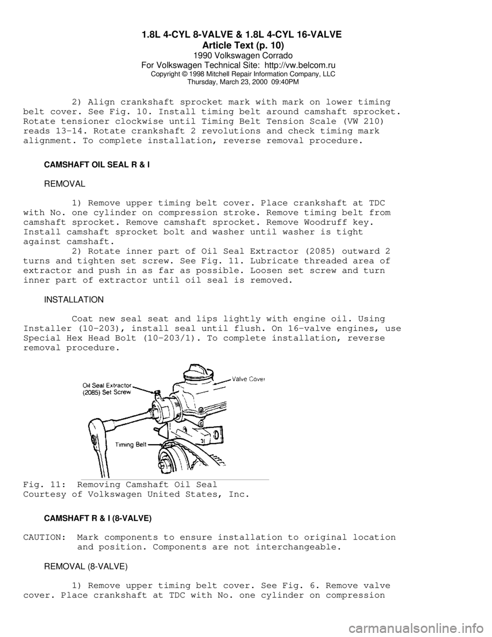
turns and tighten set screw. See Fig. 11. Lubricate threaded area of
extractor and push in as far as possible. Loosen set screw and turn
inner part of extractor until oil seal is removed.
INSTALLATION
Coat new seal seat and lips lightly with engine oil. Using
Installer (10-203), install seal until flush. On 16-valve engines, use
Special Hex Head Bolt (10-203/1). To complete installation, reverse
removal procedure.Fig. 11: Removing Camshaft Oil Seal
Courtesy of Volkswagen United States, Inc.
CAMSHAFT R & I (8-VALVE)
CAUTION: Mark components to ensure installation to original location
and position. Components are not interchangeable.
REMOVAL (8-VALVE)
1) Remove upper timing belt cover. See Fig. 6. Remove valve
cover. Place crankshaft at TDC with No. one cylinder on compression
Page 319 of 906

A/C COMPRESSOR OIL CHECKING
Article Text
1990 Volkswagen Corrado
For Volkswagen Technical Site: http://vw.belcom.ru
Copyright © 1998 Mitchell Repair Information Company, LLC
Thursday, March 23, 2000 09:41PM
ARTICLE BEGINNING
1990 AIR CONDITIONING & HEAT
Compressor Oil Checking
ISOLATING COMPRESSOR
NOTE: Only compressors with stem-type service valves can be
isolated.
1) Connect service gauge set to the compressor service valves
and open compressor valves slightly (turn in clockwise). Start engine
and operate air conditioning. Slowly turn compressor suction valve
clockwise toward closed (front-seated) position.
2) When suction pressure is reduced to zero or less, turn off
engine and compressor and quickly turn suction valve stem in to full
front-seated position. Suction pressure should be slightly above zero.
Turn discharge valve into front-seated position.
3) To check oil level, slowly open compressor crankcase plug
to relieve any remaining pressure. After oil level is corrected, cap
service gauge ports on both valves. Back-seat suction service valve to
allow refrigerant to enter compressor. Open discharge valve halfway.
4) Loosen discharge service valve cap, allowing refrigerant
pressure to force air out of compressor. Back-seat service valve and
tighten cap. Compressor is now ready for operation.
REFRIGERANT OIL
Only new, pure, moisture-free refrigerant oil should be used
in the air conditioning system. This oil is highly refined and
dehydrated to a point where moisture content is less than 10 parts per
million. The oil container must be tightly closed at all times when
not in use, or moisture will be absorbed into the refrigerant oil from
the air.
SERVICING PRECAUTIONS
NOTE: Recent findings by the EPA indicate that refrigerant is
harmful to the earth's protective Ozone layer. When
discharging refrigerant, DO NOT allow refrigerant to enter
the atmosphere. If available, use refrigerant
recovery/recycle systems when discharging system. Always
follow manufacturer's instructions.
DISCHARGING SYSTEM PRECAUTIONS
If compressor has stem-type service valves, it can be
isolated and removed without discharging entire system. See ISOLATING
COMPRESSOR at the beginning of this article. Otherwise, discharge
system completely before loosening any fittings.
Page 327 of 906

A/C COMPRESSOR SERVICING
Article Text
1990 Volkswagen Corrado
For Volkswagen Technical Site: http://vw.belcom.ru
Copyright © 1998 Mitchell Repair Information Company, LLC
Thursday, March 23, 2000 09:41PM
ARTICLE BEGINNING
1990 AIR CONDITIONING & HEAT
Compressor Service
* PLEASE READ THIS FIRST *
CAUTION: When discharging air conditioning system, use only approved
refrigerant recovery/recycling equipment. Make every attempt
to avoid discharging refrigerant into the atmosphere.
ISOLATING COMPRESSOR
NOTE: Only compressors with stem-type service valves can be
isolated.
1) Connect service gauge set to the compressor service valves
and open compressor valves slightly (turn in clockwise). Start engine
and operate air conditioning. Slowly turn compressor suction valve
clockwise toward closed (front-seated) position.
2) When suction pressure is reduced to zero or less, turn off
engine and compressor and quickly turn suction valve stem in to full
front-seated position. Suction pressure should be slightly above zero.
Turn discharge valve into front-seated position.
3) To check oil level, slowly open compressor crankcase plug
to relieve any remaining pressure. After oil level is corrected, cap
service gauge ports on both valves. Back-seat suction service valve to
allow refrigerant to enter compressor. Open discharge valve halfway.
4) Loosen discharge service valve cap, allowing refrigerant
pressure to force air out of compressor. Back-seat service valve and
tighten cap. Compressor is now ready for operation.
REFRIGERANT OIL
Only new, pure, moisture-free refrigerant oil should be used
in the air conditioning system. This oil is highly refined and
dehydrated to a point where moisture content is less than 10 parts per
million. The oil container must be tightly closed at all times when
not in use, or moisture will be absorbed into the refrigerant oil from
the air.
DISCHARGING SYSTEM PRECAUTIONS
CAUTION: When discharging air conditioning system, use only approved
refrigerant recovery/recycling equipment. Make every attempt
to avoid discharging refrigerant into the atmosphere.
If compressor has stem-type service valves, it can be
isolated and removed without discharging entire system. Otherwise,
discharge system completely using approved refrigerant
Page 362 of 906

A/C-HEATER SYSTEM - MANUAL
Article Text (p. 5)
1990 Volkswagen Corrado
For Volkswagen Technical Site: http://vw.belcom.ru
Copyright © 1998 Mitchell Repair Information Company, LLC
Thursday, March 23, 2000 09:41PM
MICROSWITCH
Loosen microswitch mounting screw. Move microswitch so switch
is on when lever is at maximum A/C, NORM (normal), BI-LEVEL or extreme
right position, and off when lever is at VENT or HEAT position.
Tighten microswitch mounting screw. Recheck operation.
TEMPERATURE SWITCH
Move temperature lever to full cool position. Loosen
temperature switch mounting screw. Move temperature switch
counterclockwise to full stop position. Tighten temperature switch
mounting screw.
TROUBLE SHOOTING
NO COOLING
1) Ensure fan motor operates in all 4 speeds, air duct closes
off outside air and heater water valve is closed. Adjust belt tension.
2) Inspect receiver-drier pressure seal. If seal is good, go
to step 5). If seal is broken, evacuate and recharge system. If system
cools properly, testing is complete. If system does not cool, connect
pressure gauges.
3) Set engine speed at 2500 RPM. Insert thermometer in left
register and close all others. Place controls on high blower and
maximum cooling. With vehicle out of direct sunlight, close all
windows. Radiator fan should come on with system pressure at 200 psi
(14 kg/cmý).
NOTE: If system doors allow air leaks, evaporator will freeze up
and testing will not be possible.
4) If fan does not operate, replace pressure switch. Ensure
system is okay. If fan does come on, turn engine off and check for
condenser obstructions and blocked airflow.
5) Turn air conditioner on and off with temperature control
lever. Ensure compressor clutch engages. Push lever to extreme right
position and back again. A click should be heard from compressor
clutch. If a click is not heard, check for voltage at clutch coil wire
with switch on. If voltage is present, replace clutch coil. If voltage
is not present, check wiring or replace thermostatic switch.
6) If compressor clutch operates, check gauge readings. If
both are low, locate leak and recharge system. If both are high,
replace expansion valve. If low side is too high and high side reads
too low, replace or rebuild compressor.
INSUFFICIENT COOLING
1) Ensure fan motor operates at all 4 speeds, air duct closes
off outside air intake and heater water valve is closed. Adjust
compressor belt tension and clean condenser.
Page 402 of 906

ALTERNATOR & REGULATOR - BOSCH
Article Text
1990 Volkswagen Corrado
For Volkswagen Technical Site: http://vw.belcom.ru
Copyright © 1998 Mitchell Repair Information Company, LLC
Thursday, March 23, 2000 09:42PM
ARTICLE BEGINNING
1989-92 ELECTRICAL
Alternators & Regulators - Bosch
Cabriolet, Fox, Golf, GTI, Jetta, Jetta GLI, Vanagon
1991 Corrado, Passat & Golf GL
NOTE: Some Golf, GTI, Jetta and Jetta GLI models may use a
Motorola alternator. Please refer to ALTERNATORS - SEV
MOTOROLA article. Vanagon models only use Bosch 90-amp
alternators.
DESCRIPTION
Bosch alternators are conventional 3-phase, self-rectifying
type alternators. Bosch 65 through 75-amp alternators use 3 positive
and 3 negative diodes connected to stator windings to rectify current.
Bosch 90-amp alternators use 14 diodes.
All alternators use 3 exciter diodes connected to stator
windings. These diodes turn off the alternator indicator light and
supply power to the voltage regulator while the engine is running.
Bosch regulators are transistorized and integral with alternator.
BELT TENSION ADJUSTMENT
BELT TENSION SPECIFICATIONSÄÄÄÄÄÄÄÄÄÄÄÄÄÄÄÄÄÄÄÄÄÄÄÄÄÄÄÄÄÄÄÄÄÄÄÄÄÄÄÄÄÄÄÄÄÄÄÄÄÄÄÄÄÄÄApplication (1) Deflection In. (mm)
New Belt ................................... 5/64 (2)
Used Belt ................................. 13/64 (5)
(1) - Deflection is with 22 lbs. (10 kg) pressure
applied midway on longest belt run.
ÄÄÄÄÄÄÄÄÄÄÄÄÄÄÄÄÄÄÄÄÄÄÄÄÄÄÄÄÄÄÄÄÄÄÄÄÄÄÄÄÄÄÄÄÄÄÄÄÄÄÄÄÄÄÄ TESTING (ON-VEHICLE)
WIRING CONTINUITY TEST
1) Connect a voltmeter between alternator "B+" terminal and
ground. Voltmeter should indicate battery voltage. If not, check
wiring between alternator and battery.
2) Turn ignition on and ensure alternator indicator light
comes on. If light does not come on, check wiring between alternator
and warning light, including indicator bulb.
OUTPUT TEST
1) Ensure connections at battery, alternator, and starter
Page 412 of 906

ANTI-LOCK BRAKE SYSTEM
Article Text (p. 4)
1990 Volkswagen Corrado
For Volkswagen Technical Site: http://vw.belcom.ru
Copyright © 1998 Mitchell Repair Information Company, LLC
Thursday, March 23, 2000 09:42PM
seconds maximum and then stop. Depress brake pedal a few times; pump
should operate again for a few seconds. If pump motor does not
operate, check electrical system. If pump motor operates for more than
60 seconds, internal or external hydraulic leak may be indicated.
Check for external leaks. If external leak is not found, further
testing may be needed to check for internal leaks.
ANTI-LOCK WARNING LIGHT
Start engine. ANTI-LOCK warning light should come on, then
turn off after a few seconds. If light does not come on when engine is
started, check electrical system. If light comes on and stays on,
fault has been detected by the ECU and testing will be needed. See
SYSTEM TESTING under DIAGNOSIS & TESTING.
DIAGNOSIS & TESTING
SYSTEM TESTING
NOTE: Check battery condition, brake fluid level, electrical
connections and wiring for damage. If fluid level is
incorrect or battery and/or electrical connections are
faulty, correct problem before preceding. Perform each step,
in sequence, to test entire system, except for ECU. If
faulty ECU is suspected, replace with a known good one, and
retest system. Unplug ECU connector for all test steps.
Power Voltage-To-ECU Test
Turn ignition off. Unplug ECU connector. Turn ignition on.
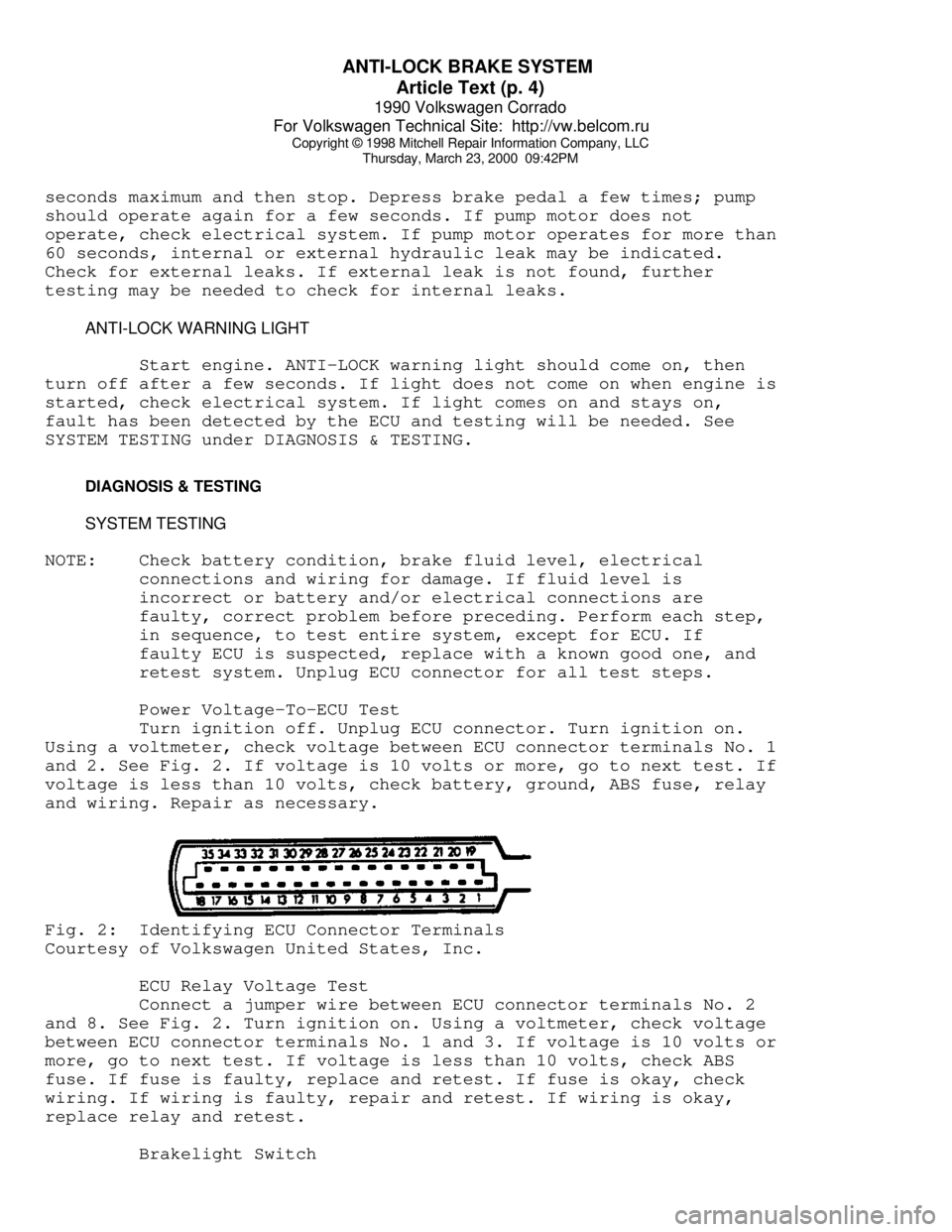
Using a voltmeter, check voltage between ECU connector terminals No. 1
and 2. See Fig. 2. If voltage is 10 volts or more, go to next test. If
voltage is less than 10 volts, check battery, ground, ABS fuse, relay
and wiring. Repair as necessary.Fig. 2: Identifying ECU Connector Terminals
Courtesy of Volkswagen United States, Inc.
ECU Relay Voltage Test
Connect a jumper wire between ECU connector terminals No. 2
and 8. See Fig. 2. Turn ignition on. Using a voltmeter, check voltage
between ECU connector terminals No. 1 and 3. If voltage is 10 volts or
more, go to next test. If voltage is less than 10 volts, check ABS
fuse. If fuse is faulty, replace and retest. If fuse is okay, check
wiring. If wiring is faulty, repair and retest. If wiring is okay,
replace relay and retest.
Brakelight Switch
Page 427 of 906

B - EMISSION APPLICATION
Article Text
1990 Volkswagen Corrado
For Volkswagen Technical Site: http://vw.belcom.ru
Copyright © 1998 Mitchell Repair Information Company, LLC
Thursday, March 23, 2000 09:43PM
ARTICLE BEGINNING
1990 ENGINE EMISSIONS
Emission Control Applications
Cabriolet, Corrado, Fox, Golf, Jetta, Passat, Vanagon
EMISSION CONTROL DEVICE APPLICATIONS
EMISSION CONTROL DEVICE APPLICATIONS TABLEÄÄÄÄÄÄÄÄÄÄÄÄÄÄÄÄÄÄÄÄÄÄÄÄÄÄÄÄÄÄÄÄÄÄÄÄÄÄÄÄÄÄÄÄÄÄÄÄÄÄÄÄÄÄÄÄÄÄÄÄÄÄÄÄÄApplication Devices
Cabriolet 1.8L (CIS-E) PCV, EVAP, TWC, SPK, O2, CEC,
EVAP-PV, EVAP-VC, SPK-CC, VA
Corrado 1.8L (PFI) PCV, EVAP, TWC, O2, CEC,
PCV-HCB, EVAP-PV, EVAP-VC, SPK-CC
Fox 1.8L (CIS-E) PCV, EVAP, TWC, EGR (Calif.), O2,
CEC, EVAP-VC, EVAP-VS, EGR-VA (Calif.),
EGR-TVV (Calif.), SPK-CC, VA
Golf & Jetta
1.8L (CIS-E) PCV, EVAP, TWC, SPK, O2, CEC,
CE, EVAP-VC, EVAP-PV, SPK-CC, VA
2.0L (CIS-E) PCV, EVAP, TWC, EGR, SPK, O2, CEC,
CE, EVAP-VC, EGR-TVV, SPK-CC,
Passat 2.0L CIS-E PCV, EVAP, TWC, EGR (Calif.),
SPK, O2, CEC, CE, EVAP-VC,
EVAP-SV, EGR-TVV, SPK-CC,
Vanagon PFI PCV, EVAP, TWC, EGR, SPK, O2, CEC, EMR,
CE, EVAP-VC, EVAP-PV, SPK-CC, VA, VR
ÄÄÄÄÄÄÄÄÄÄÄÄÄÄÄÄÄÄÄÄÄÄÄÄÄÄÄÄÄÄÄÄÄÄÄÄÄÄÄÄÄÄÄÄÄÄÄÄÄÄÄÄÄÄÄÄÄÄÄÄÄÄÄÄÄ ABBREVIATION DEFINITIONS
CEC - Computerized Engine Control
CE - Check Engine Light
CIS-E - Continuous Injection System-Electronic
EGR - Exhaust Gas Recirculation
EGR-VA - EGR-Vacuum Amplifier
EGR-TS - EGR Temperature Sensor
EGR-TVV - EGR Thermal Vacuum Valve
EVAP - Fuel Evaporation System
EVAP-CS - EVAP Control Solenoid