relay VOLKSWAGEN CORRADO 1993 Owner's Manual
[x] Cancel search | Manufacturer: VOLKSWAGEN, Model Year: 1993, Model line: CORRADO, Model: VOLKSWAGEN CORRADO 1993Pages: 920, PDF Size: 6.92 MB
Page 420 of 920
ANTI-LOCK BRAKE SYSTEM
Article Text (p. 10)
1993 Volkswagen Corrado
For Volkswagen Technical Site: http://vw.belcom.ru
Copyright © 1998 Mitchell Repair Information Company, LLC
Wednesday, March 22, 2000 08:57PM
Left Front Hydraulic Modulator Outlet Valve Resistance Test
Using an ohmmeter, measure resistance between ECU connector
terminals No. 11 and 16. See Fig. 2. If resistance is 3-5 ohms, go to
next test. If resistance is not 3-5 ohms, measure between hydraulic
modulator terminals No. 1 (Brown wire) and No. 6 (Black/Blue wire).
See Fig. 4. If resistance is 3-5 ohms, check wiring between hydraulic
modulator and ECU for open circuit. If resistance is not 3-5 ohms,
replace hydraulic modulator.
Hydraulic Modulator/Pump Relay Resistance Test
Turn ignition off. Unplug pressure switch connector from
hydraulic modulator. Using an ohmmeter, measure resistance between ECU
connector terminals No. 2 and 14. See Fig. 2. If resistance is 50-100
ohms, go to next test. If resistance is not 50-100 ohms, check wiring.
If wiring is faulty, repair wiring and retest. If wiring is okay,
replace relay and retest.
ABS Main Valve Function Test
Connect a jumper wire between ECU connector terminals No. 2
and 18. See Fig. 2. Depress brake pedal. Turn ignition on. Brake pedal
should rise slightly. If brake pedal did not rise slightly, check
wiring between terminals and hydraulic modulator. If wiring is okay,
replace hydraulic modulator.
Hydraulic Modulator/Pump Test
Turn ignition off. Depress brake pedal 25 times. Turn
ignition on. BRAKE and ANTILOCK lights should come on for 2-60
seconds. Pump should operate for 2-60 seconds, then turn off. If
lights do not come on, check wiring and warning light bulbs, and
retest. Also check bulb(s). If lights come on, then turn off, and pump
operates for 60 seconds maximum, then turns off, go to next test. If
pump does not operate and all other preceding tests have been
performed, replace hydraulic modulator/pump.
CAUTION: During VALVE BLOCK FUNCTION TESTS, DO NOT turn ignition on
longer than 60 seconds during any test.
Rear Valve Block Function Test
Connect a jumper wire ECU between ECU connector terminals No.
2, 17 and 33. See Fig. 2. Depress brake pedal. Rear wheels should be
locked up. Turn ignition on. Rear wheels should rotate. If wheels do
not rotate, replace hydraulic modulator. Turn ignition off.
Right Front Valve Block Function Test
Connect a jumper wire ECU between ECU connector terminals No.
2, 15 and 34. See Fig. 2. Depress brake pedal. Right front wheel
should be locked up. Turn ignition on. Right front wheel should
rotate. If wheel does not rotate, replace hydraulic modulator. Turn
ignition off.
Left Front Valve Block Function Test
Page 423 of 920
ANTI-THEFT SYSTEM
Article Text
1993 Volkswagen Corrado
For Volkswagen Technical Site: http://vw.belcom.ru
Copyright © 1998 Mitchell Repair Information Company, LLC
Wednesday, March 22, 2000 08:57PM
ARTICLE BEGINNING
1993 ACCESSORIES & EQUIPMENT
Volkswagen Anti-Theft
Volkswagen; Corrado SLC, Passat
DESCRIPTION & OPERATION
The anti-theft system monitors the radio, all doors, hood and
trunk lid position. When the anti-theft system is activated, The horn
and emergency flashers will be activated and the vehicle will not
start. The windows and sun roof (if equipped) are not monitored.
The anti-theft system has self-diagnostic capabilities that
monitor all components and wiring harness. If the system is
functioning correctly, the horn will sound briefly after front door is
locked with the key.
ANTI-THEFT CONTROL MODULE LOCATION TABLEÄÄÄÄÄÄÄÄÄÄÄÄÄÄÄÄÄÄÄÄÄÄÄÄÄÄÄÄÄÄÄÄÄÄÄÄÄÄÄÄÄÄÄÄÄÄÄÄÄÄÄÄÄÄÄÄÄÄÄÄModel Location
Corrado SLC ...................... Behind Right Kick Panel
Passat ...................... Driver Side Fuse/Relay Panel
ÄÄÄÄÄÄÄÄÄÄÄÄÄÄÄÄÄÄÄÄÄÄÄÄÄÄÄÄÄÄÄÄÄÄÄÄÄÄÄÄÄÄÄÄÄÄÄÄÄÄÄÄÄÄÄÄÄÄÄÄ TROUBLE SHOOTING
SYSTEM DOES NOT OPERATE
NOTE: Ensure battery is fully charged and all fuses are okay.
1) Ground Circuit Check
Obtain radio security code. Disconnect battery cable
terminals. Disconnect anti-theft control module 6-pin and 10-pin
wiring harness connector. See ANTI-THEFT CONTROL MODULE LOCATION
table. Connect ohmmeter negative lead to ground. Connect positive lead
to anti-theft control module 10-pin wiring harness connector terminal
No. "3" (Brown wire). If continuity is present, go to next step. If
continuity is not present, repair open circuit.
2) Power Circuit Check
Connect battery cable terminals. Connect voltmeter negative
lead to ground. Connect positive lead to anti-theft control module 6-
pin wiring harness connector terminal No. "3" (Red wire). Switch
positive lead to anti-theft control module 10-pin wiring harness
connector terminal No. "1" (Red wire). If 12 volts are present at both
terminals, go to next step. If 12 volts are not present, repair open
circuit.
3) Turn ignition on. Leave voltmeter negative lead connected
to ground. Connect positive lead to anti-theft control module 10-pin
wiring harness connector terminal No. "4" (Black wire for Corrado;
Page 431 of 920
B - EMISSION APPLICATION
Article Text (p. 2)
1993 Volkswagen Corrado
For Volkswagen Technical Site: http://vw.belcom.ru
Copyright © 1998 Mitchell Repair Information Company, LLC
Wednesday, March 22, 2000 08:57PM
2.0L 4-Cyl. CIS-E Motronic
Major Control Systems & Devices ............. PCV, EVAP, TWC, FR,
(2) EGR, SPK, AP,
(1) O2, CEC, (2) MIL
Components & Other Related Devices ........ (4) EVAP-PV, EVAP-CV,
EGR-VA, EGR-TVV, SPK-CC
2.8L VR6 Motronic MFI
Major Control Systems & Devices ........ PCV, EVAP, TWC, FR, EGR,
SPK, AP, (1) O2, CEC, (2) MIL
Components & Other Related Devices ...... AP-EAP, AP-ERLY, AP-SV,
AP-SOV, EVAP-PV, EVAP-VC,
EGR-CV, EGR-TS, SPK-CC
(1) - Heated O2 sensor.
(2) - California only.
(3) - Digifant II only.
(4) - Two required.ÄÄÄÄÄÄÄÄÄÄÄÄÄÄÄÄÄÄÄÄÄÄÄÄÄÄÄÄÄÄÄÄÄÄÄÄÄÄÄÄÄÄÄÄÄÄÄÄÄÄÄÄÄÄÄÄÄÄÄÄÄÄÄÄÄÄÄÄÄÄ ABBREVIATION DEFINITIONS
ABBREVIATION DEFINITION TABLE
ÄÄÄÄÄÄÄÄÄÄÄÄÄÄÄÄÄÄÄÄÄÄÄÄÄÄÄÄÄÄÄÄÄÄÄÄÄÄÄÄÄÄÄÄÄÄÄÄÄÄÄÄÄÄÄÄÄÄÄÄAbbreviation Definition
AP ............................. Air Pump Injection System
AP-EAP .............................. AP Electric Air Pump
AP-ERLY ....................... AP Electric Air Pump Relay
AP-SV .......................... AP Solenoid (Inlet) Valve
AP-SOV ................................. AP Shut Off Valve
CEC ......................... Computerized Engine Controls
EGR ............................ Exhaust Gas Recirculation
EGR-CV ..................... EGR Control (Frequency) Valve
EGR-TS ............................ EGR Temperature Sensor
EGR-TVV ......................... EGR Thermal Vacuum Valve
EGR-VA .............................. EGR Vacuum Amplifier
EVAP ............................. Fuel Evaporative System
EVAP-CS ............................ EVAP Control Solenoid
EVAP-PV ................................. EVAP Purge Valve
EVAP-VC .............................. EVAP Vapor Canister
FR .................................. Fill Pipe Restrictor
HAI ....................................... Hot Air Intake
MIL ........... Malfunction Indicator (CHECK ENGINE) Light
MFI ............................. Multiport Fuel Injection
O2 ......................................... Oxygen Sensor
PCV ....................... Positive Crankcase Ventilation
SPK ................................. Spark Control System
SPK-CC ........................... SPK Computer Controlled
TWC ................................... Three-Way Catalyst
ÄÄÄÄÄÄÄÄÄÄÄÄÄÄÄÄÄÄÄÄÄÄÄÄÄÄÄÄÄÄÄÄÄÄÄÄÄÄÄÄÄÄÄÄÄÄÄÄÄÄÄÄÄÄÄÄÄÄÄÄEND OF ARTICLE
Page 444 of 920
C - SPECIFICATIONS
Article Text (p. 4)
1993 Volkswagen Corrado
For Volkswagen Technical Site: http://vw.belcom.ru
Copyright © 1998 Mitchell Repair Information Company, LLC
Wednesday, March 22, 2000 08:58PM
IGNITION TIMING
NOTE: Always refer to underhood label for latest specifications.
IGNITION TIMING (Degrees BTDC @ RPM)ÄÄÄÄÄÄÄÄÄÄÄÄÄÄÄÄÄÄÄÄÄÄÄÄÄÄÄÄÄÄÄÄÄÄÄÄÄÄÄÄÄÄÄÄÄÄÄÄÄÄÄÄÄÄÄApplication Checking Adjusting
Corrado SLC ............... (1) ............... (1)
(1) - Ignition timing is computer controlled.
Information is not available from manufacturer.
ÄÄÄÄÄÄÄÄÄÄÄÄÄÄÄÄÄÄÄÄÄÄÄÄÄÄÄÄÄÄÄÄÄÄÄÄÄÄÄÄÄÄÄÄÄÄÄÄÄÄÄÄÄÄÄIGNITION TIMING ADVANCE (Degrees BTDC @ RPM)
ÄÄÄÄÄÄÄÄÄÄÄÄÄÄÄÄÄÄÄÄÄÄÄÄÄÄÄÄÄÄÄÄÄÄÄÄÄÄÄÄÄÄÄÄÄÄÄÄÄÄÄÄÄÄÄApplication Specification
Corrado SLC ..................................... (1)
(1) - Ignition timing advance is computer controlled.
Information is not available from manufacturer.
ÄÄÄÄÄÄÄÄÄÄÄÄÄÄÄÄÄÄÄÄÄÄÄÄÄÄÄÄÄÄÄÄÄÄÄÄÄÄÄÄÄÄÄÄÄÄÄÄÄÄÄÄÄÄÄ FUEL SYSTEM
FUEL PUMP
NOTE: Fuel pump performance measures fuel pressure and volume
availability, not regulated fuel pressure.
FUEL PUMP PERFORMANCE
ÄÄÄÄÄÄÄÄÄÄÄÄÄÄÄÄÄÄÄÄÄÄÄÄÄÄÄÄÄÄÄÄÄÄÄÄÄÄÄÄÄÄÄÄÄÄÄÄÄÄÄÄÄÄÄÄÄÄÄÄÄÄÄÄÄ Pressure Min. Vol. In 30 Sec.
Application psi (kg/cm(
ý) Pts. (L)
Corrado SLC (1) .......... 58 (4.0) ....... 1.0-1.4 (0.5-0.7)
(1) - Using Adapter Cable (VAG 1348/3-2) between battery positive
terminal and terminal No. 4 of fuel pump relay socket. Fuel
pump energized, with 10-12 volts at fuel pump and engine off.
ÄÄÄÄÄÄÄÄÄÄÄÄÄÄÄÄÄÄÄÄÄÄÄÄÄÄÄÄÄÄÄÄÄÄÄÄÄÄÄÄÄÄÄÄÄÄÄÄÄÄÄÄÄÄÄÄÄÄÄÄÄÄÄÄÄREGULATED FUEL PRESSURE
ÄÄÄÄÄÄÄÄÄÄÄÄÄÄÄÄÄÄÄÄÄÄÄÄÄÄÄÄÄÄÄÄÄÄÄÄÄÄÄÄÄÄÄÄÄÄÄÄÄÄÄÄÄÄÄÄÄÄÄÄÄÄÄÄÄ At Idle At Idle
w/Vacuum w/o Vacuum
Application psi (kg/cm
ý) (1) psi (kg/cmý)
Corrado SLC ............ 50 (3.5) .................. 58 (4.0)
(1) - With vacuum hose disconnected from fuel pressure regulator.
Page 459 of 920
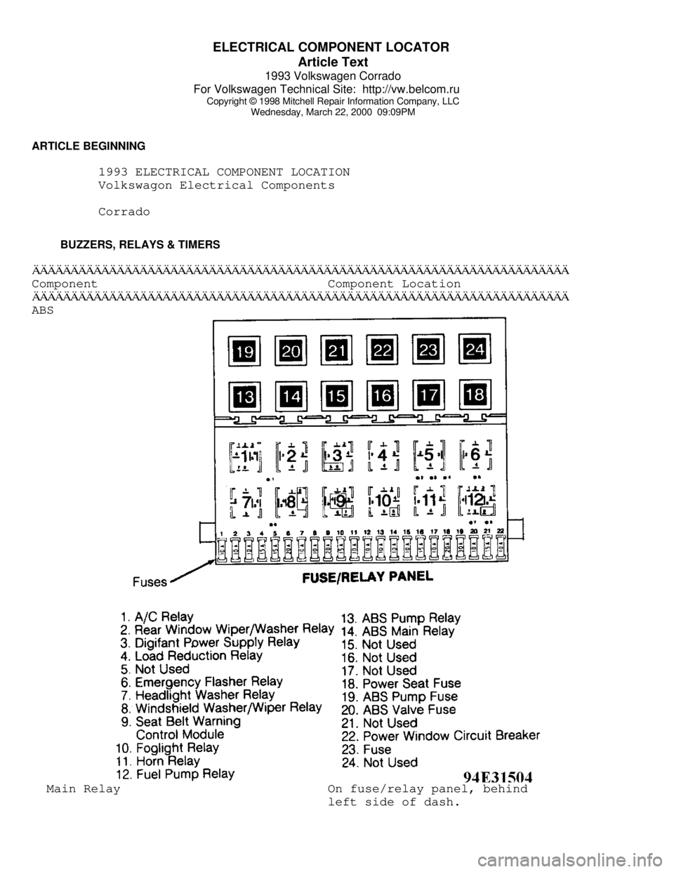
ELECTRICAL COMPONENT LOCATOR
Article Text
1993 Volkswagen Corrado
For Volkswagen Technical Site: http://vw.belcom.ru
Copyright © 1998 Mitchell Repair Information Company, LLC
Wednesday, March 22, 2000 09:09PM
ARTICLE BEGINNING
1993 ELECTRICAL COMPONENT LOCATION
Volkswagon Electrical Components
Corrado
BUZZERS, RELAYS & TIMERSÄÄÄÄÄÄÄÄÄÄÄÄÄÄÄÄÄÄÄÄÄÄÄÄÄÄÄÄÄÄÄÄÄÄÄÄÄÄÄÄÄÄÄÄÄÄÄÄÄÄÄÄÄÄÄÄÄÄÄÄÄÄÄÄÄÄÄÄÄÄComponent Component Location
ÄÄÄÄÄÄÄÄÄÄÄÄÄÄÄÄÄÄÄÄÄÄÄÄÄÄÄÄÄÄÄÄÄÄÄÄÄÄÄÄÄÄÄÄÄÄÄÄÄÄÄÄÄÄÄÄÄÄÄÄÄÄÄÄÄÄÄÄÄÄABS Main Relay On fuse/relay panel, behind
left side of dash.
Page 460 of 920
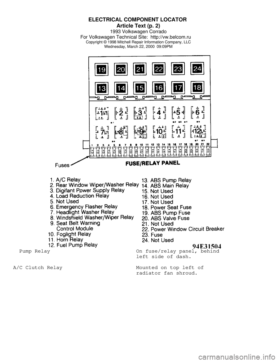
ELECTRICAL COMPONENT LOCATOR
Article Text (p. 2)
1993 Volkswagen Corrado
For Volkswagen Technical Site: http://vw.belcom.ru
Copyright © 1998 Mitchell Repair Information Company, LLC
Wednesday, March 22, 2000 09:09PM Pump Relay On fuse/relay panel, behind
left side of dash.
A/C Clutch Relay Mounted on top left of
radiator fan shroud.
Page 461 of 920
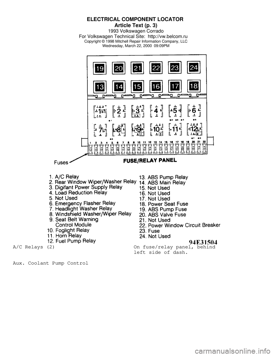
ELECTRICAL COMPONENT LOCATOR
Article Text (p. 3)
1993 Volkswagen Corrado
For Volkswagen Technical Site: http://vw.belcom.ru
Copyright © 1998 Mitchell Repair Information Company, LLC
Wednesday, March 22, 2000 09:09PMA/C Relays (2) On fuse/relay panel, behind
left side of dash.
Aux. Coolant Pump Control
Page 462 of 920
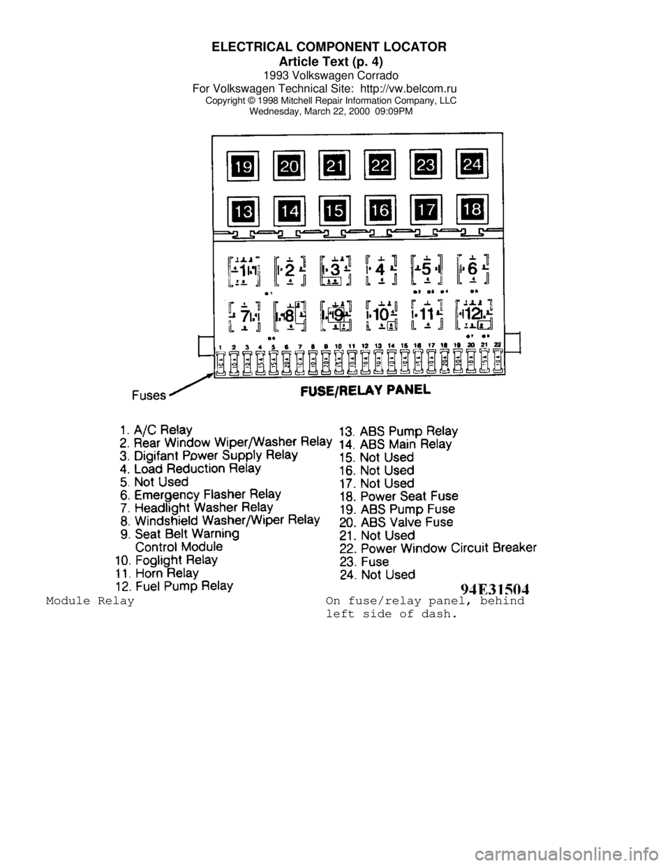
ELECTRICAL COMPONENT LOCATOR
Article Text (p. 4)
1993 Volkswagen Corrado
For Volkswagen Technical Site: http://vw.belcom.ru
Copyright © 1998 Mitchell Repair Information Company, LLC
Wednesday, March 22, 2000 09:09PM Module Relay On fuse/relay panel, behind
left side of dash.
Page 463 of 920
ELECTRICAL COMPONENT LOCATOR
Article Text (p. 5)
1993 Volkswagen Corrado
For Volkswagen Technical Site: http://vw.belcom.ru
Copyright © 1998 Mitchell Repair Information Company, LLC
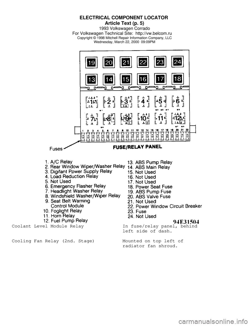
Wednesday, March 22, 2000 09:09PMCoolant Level Module Relay In fuse/relay panel, behind
left side of dash.
Cooling Fan Relay (2nd. Stage) Mounted on top left of
radiator fan shroud.
Page 464 of 920
ELECTRICAL COMPONENT LOCATOR
Article Text (p. 6)
1993 Volkswagen Corrado
For Volkswagen Technical Site: http://vw.belcom.ru
Copyright © 1998 Mitchell Repair Information Company, LLC
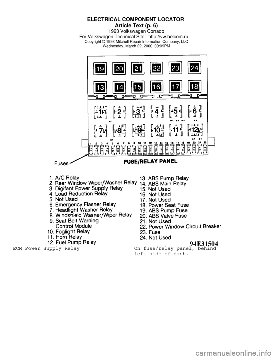
Wednesday, March 22, 2000 09:09PMECM Power Supply Relay On fuse/relay panel, behind
left side of dash.