VOLKSWAGEN CORRADO 1993 Repair Manual
Manufacturer: VOLKSWAGEN, Model Year: 1993, Model line: CORRADO, Model: VOLKSWAGEN CORRADO 1993Pages: 920, PDF Size: 6.92 MB
Page 571 of 920

F - BASIC TESTING
Article Text (p. 6)
1993 Volkswagen Corrado
For Volkswagen Technical Site: http://vw.belcom.ru
Copyright © 1998 Mitchell Repair Information Company, LLC
Wednesday, March 22, 2000 09:10PM
EuroVan ................ 36 (2.5) .................. 43 (3.0)
Passat GL ........ (2) 87-94 (6.1-6.6) ... (3) 87-94 (6.1-6.6)
Passat GLX ............. 50 (3.5) .................. 58 (4.0)
(1) - With vacuum hose disconnected from fuel pressure regulator.
(2) - Approximately 4.3-7.2 psi (0.3-0.5 kg/cmý) below system
pressure, with differential pressure regulator disconnected.
(3) - Approximately 18.5-23.0 psi (1.3-1.6 kg/cm
ý) below system
pressure, with differential pressure regulator connected.
ÄÄÄÄÄÄÄÄÄÄÄÄÄÄÄÄÄÄÄÄÄÄÄÄÄÄÄÄÄÄÄÄÄÄÄÄÄÄÄÄÄÄÄÄÄÄÄÄÄÄÄÄÄÄÄÄÄÄÄÄÄÄÄÄÄ IGNITION CHECKS
NOTE: Ignition checks are divided according to fuel system.
SPARK TEST
1) Using an ohmmeter, check resistance of each spark plug
wire. See HIGH TENSION WIRE RESISTANCE table. Check for a strong Blue
spark at coil wire and at each spark plug wire by holding wire
terminal 5/16" from ground while cranking engine.
2) Disconnect and inspect all related ignition system
connectors and harness. Clean or repair if necessary. If related
connectors and harness are okay, remove negative battery cable.
Disconnect secondary and primary leads from ignition coil.
3) Using ohmmeter, check primary resistance between primary
terminals of coil. Check secondary resistance between coil secondary
terminal and primary positive terminal. Replace coil if readings are
not within specifications. See IGNITION COIL RESISTANCE table.
HIGH TENSION WIRE RESISTANCE TABLE
ÄÄÄÄÄÄÄÄÄÄÄÄÄÄÄÄÄÄÄÄÄÄÄÄÄÄÄÄÄÄÄÄÄÄÄÄÄÄÄÄÄÄÄÄÄÄÄÄÄÄÄÄÄÄÄApplication Ohms
Coil Wire Only .................................. (1)
Coil Wire With Connector .................. 1600-2400
Spark Plug Wire Connector ................. 4000-6000
Suppressor (2) ............................. 600-1400
(1) - Check for continuity.
(2) - Suppressor is located between ignition coil wire
and distributor cap.
ÄÄÄÄÄÄÄÄÄÄÄÄÄÄÄÄÄÄÄÄÄÄÄÄÄÄÄÄÄÄÄÄÄÄÄÄÄÄÄÄÄÄÄÄÄÄÄÄÄÄÄÄÄÄÄ IGNITION COIL
IGNITION COIL RESISTANCE - Ohms @ 68
øF (20øC)
ÄÄÄÄÄÄÄÄÄÄÄÄÄÄÄÄÄÄÄÄÄÄÄÄÄÄÄÄÄÄÄÄÄÄÄÄÄÄÄÄÄÄÄÄÄÄÄÄÄÄÄÄÄÄÄApplication Primary Secondary
Cabriolet
Digifant I ........... 0.5-0.7 ......... 3000-4000
Page 572 of 920

F - BASIC TESTING
Article Text (p. 7)
1993 Volkswagen Corrado
For Volkswagen Technical Site: http://vw.belcom.ru
Copyright © 1998 Mitchell Repair Information Company, LLC
Wednesday, March 22, 2000 09:10PM
Digifant II ......... 0.52-0.76 ........ 2400-3500
Corrado SLC (1) ........ ..... .............. .....
Fox
Digifant I ........... 0.5-0.7 ......... 3000-4000
Digifant II .......... 0.6-0.7 ......... 2500-3500
Golf, GTI & Jetta ..... 0.5-0.7 ......... 3000-4000
Passat GL ............. 0.6-0.8 ......... 6500-8500
Passat GLX (1) ......... ..... .............. .....
(1) - Ignition coil pack, new for 1993, is located on
left side of cylinder head. When ignition coil is
triggered, spark is supplied to 2 spark plugs at
one time. One spark plug fires during compression
stroke and the other plug fires during exhaust
stroke (waste spark). Ignition coil specifications
are not available from manufacturer.ÄÄÄÄÄÄÄÄÄÄÄÄÄÄÄÄÄÄÄÄÄÄÄÄÄÄÄÄÄÄÄÄÄÄÄÄÄÄÄÄÄÄÄÄÄÄÄÄÄÄÄÄÄÄÄ DISTRIBUTOR
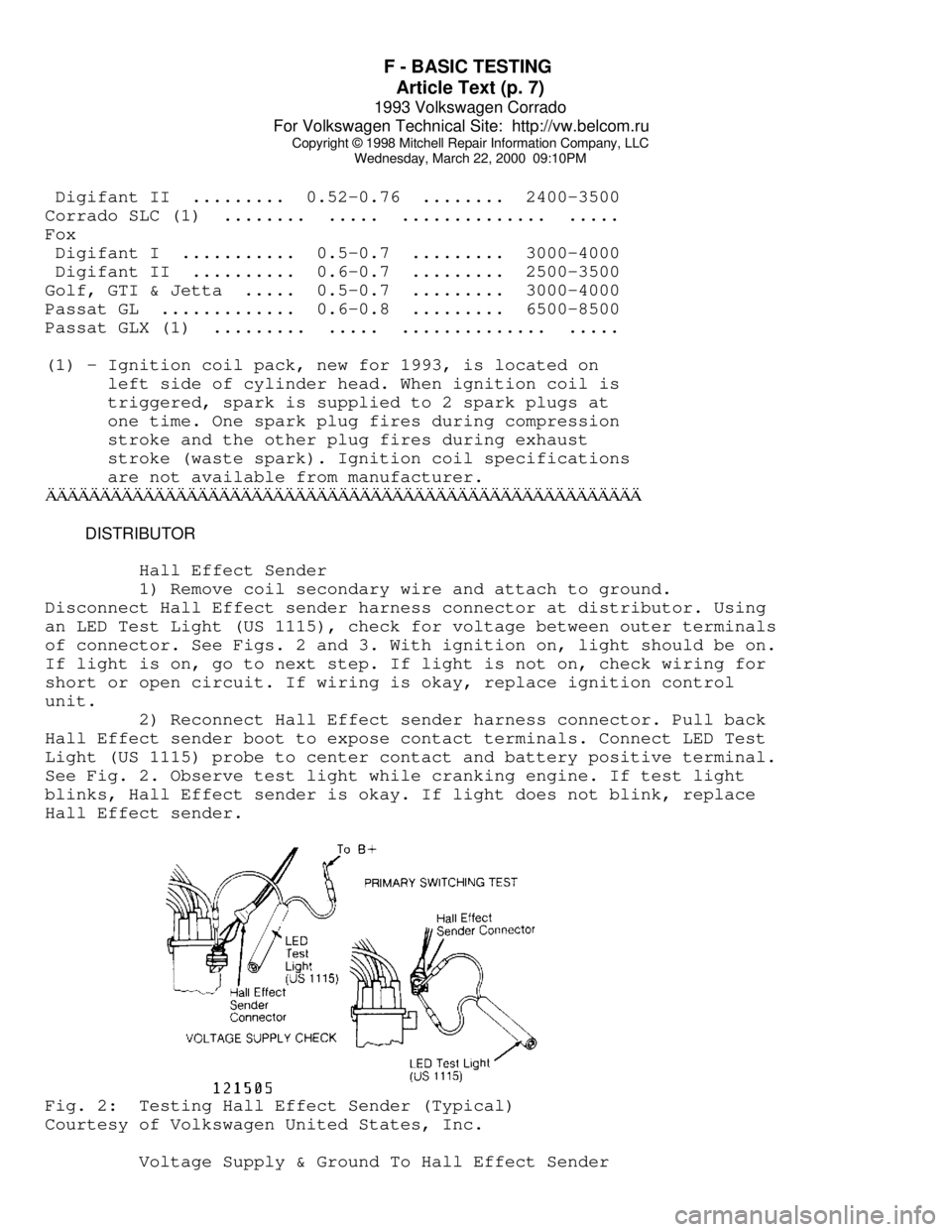
Hall Effect Sender
1) Remove coil secondary wire and attach to ground.
Disconnect Hall Effect sender harness connector at distributor. Using
an LED Test Light (US 1115), check for voltage between outer terminals
of connector. See Figs. 2 and 3. With ignition on, light should be on.
If light is on, go to next step. If light is not on, check wiring for
short or open circuit. If wiring is okay, replace ignition control
unit.
2) Reconnect Hall Effect sender harness connector. Pull back
Hall Effect sender boot to expose contact terminals. Connect LED Test
Light (US 1115) probe to center contact and battery positive terminal.
See Fig. 2. Observe test light while cranking engine. If test light
blinks, Hall Effect sender is okay. If light does not blink, replace
Hall Effect sender.Fig. 2: Testing Hall Effect Sender (Typical)
Courtesy of Volkswagen United States, Inc.
Voltage Supply & Ground To Hall Effect Sender
Page 573 of 920

F - BASIC TESTING
Article Text (p. 8)
1993 Volkswagen Corrado
For Volkswagen Technical Site: http://vw.belcom.ru
Copyright © 1998 Mitchell Repair Information Company, LLC
Wednesday, March 22, 2000 09:10PM
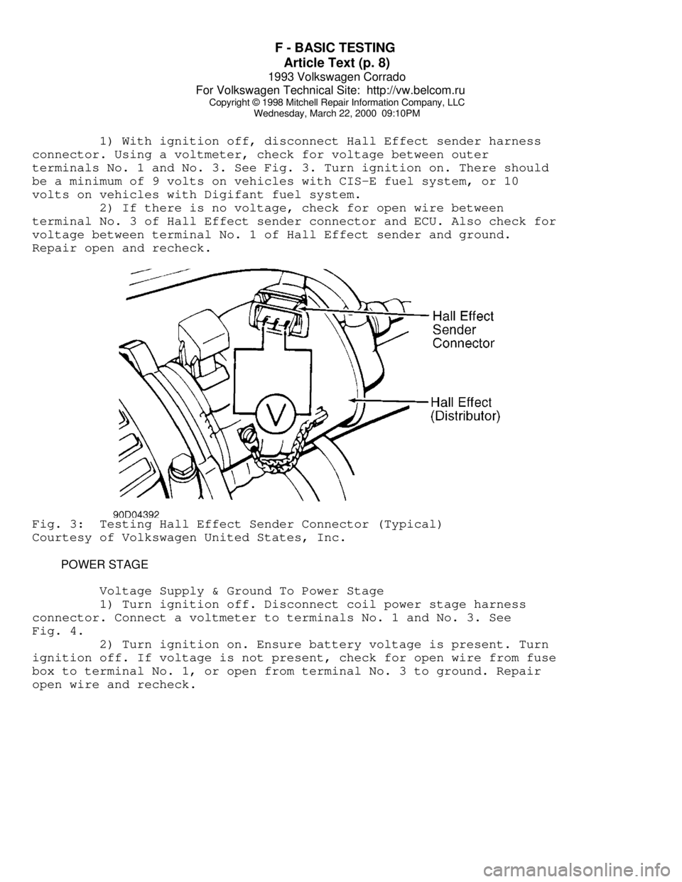
1) With ignition off, disconnect Hall Effect sender harness
connector. Using a voltmeter, check for voltage between outer
terminals No. 1 and No. 3. See Fig. 3. Turn ignition on. There should
be a minimum of 9 volts on vehicles with CIS-E fuel system, or 10
volts on vehicles with Digifant fuel system.
2) If there is no voltage, check for open wire between
terminal No. 3 of Hall Effect sender connector and ECU. Also check for
voltage between terminal No. 1 of Hall Effect sender and ground.
Repair open and recheck.Fig. 3: Testing Hall Effect Sender Connector (Typical)
Courtesy of Volkswagen United States, Inc.
POWER STAGE
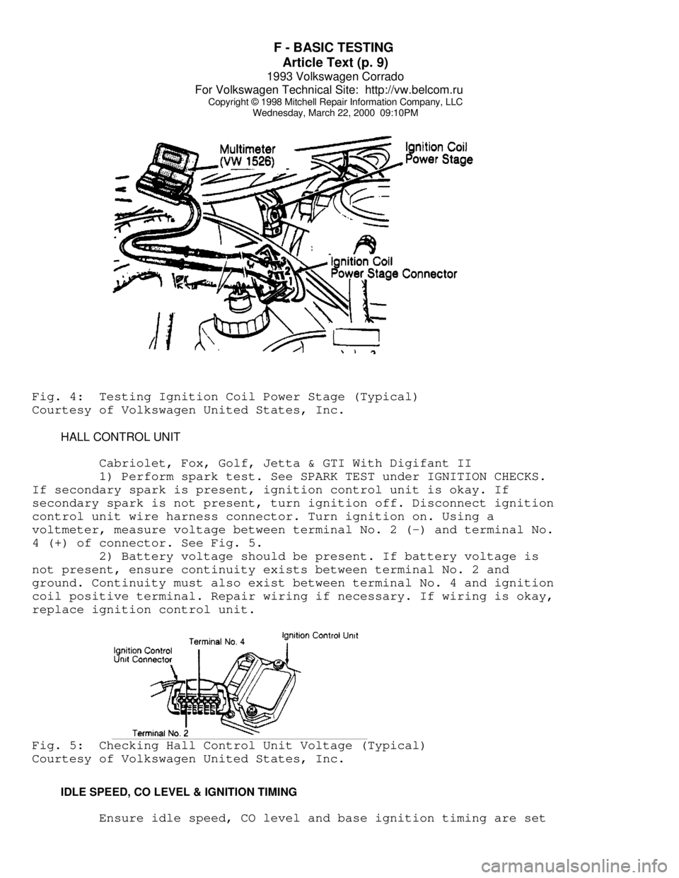
Voltage Supply & Ground To Power Stage
1) Turn ignition off. Disconnect coil power stage harness
connector. Connect a voltmeter to terminals No. 1 and No. 3. See
Fig. 4.
2) Turn ignition on. Ensure battery voltage is present. Turn
ignition off. If voltage is not present, check for open wire from fuse
box to terminal No. 1, or open from terminal No. 3 to ground. Repair
open wire and recheck.
Page 574 of 920

F - BASIC TESTING
Article Text (p. 9)
1993 Volkswagen Corrado
For Volkswagen Technical Site: http://vw.belcom.ru
Copyright © 1998 Mitchell Repair Information Company, LLC
Wednesday, March 22, 2000 09:10PMFig. 4: Testing Ignition Coil Power Stage (Typical)
Courtesy of Volkswagen United States, Inc.
HALL CONTROL UNIT
Cabriolet, Fox, Golf, Jetta & GTI With Digifant II
1) Perform spark test. See SPARK TEST under IGNITION CHECKS.
If secondary spark is present, ignition control unit is okay. If
secondary spark is not present, turn ignition off. Disconnect ignition
control unit wire harness connector. Turn ignition on. Using a
voltmeter, measure voltage between terminal No. 2 (-) and terminal No.
4 (+) of connector. See Fig. 5.
2) Battery voltage should be present. If battery voltage is
not present, ensure continuity exists between terminal No. 2 and
ground. Continuity must also exist between terminal No. 4 and ignition
coil positive terminal. Repair wiring if necessary. If wiring is okay,
replace ignition control unit.Fig. 5: Checking Hall Control Unit Voltage (Typical)
Courtesy of Volkswagen United States, Inc.
IDLE SPEED, CO LEVEL & IGNITION TIMING
Ensure idle speed, CO level and base ignition timing are set
Page 575 of 920

F - BASIC TESTING
Article Text (p. 10)
1993 Volkswagen Corrado
For Volkswagen Technical Site: http://vw.belcom.ru
Copyright © 1998 Mitchell Repair Information Company, LLC
Wednesday, March 22, 2000 09:10PM
to specification. If necessary, see the appropriate D - ADJUSTMENTS
article in this section. Refer to the following menu:
NOTE: For the appropriate D - ADJUSTMENTS article, go to:
* For Cabriolet, see: D - ADJUSTMENTS
* For Corrado SLC, see: D - ADJUSTMENTS
* For EuroVan, see: D - ADJUSTMENTS
* For Fox, see: D - ADJUSTMENTS
* For Golf, GTI, Jetta, see: D - ADJUSTMENTS
* For Passat GL 2.0L 4-Cylinder, see: D - ADJUSTMENTS - 4-CYL
* For Passat GLX 2.8L VR6, see: D - ADJUSTMENTS - VR6
IDLE SPEED & CO LEVELÄÄÄÄÄÄÄÄÄÄÄÄÄÄÄÄÄÄÄÄÄÄÄÄÄÄÄÄÄÄÄÄÄÄÄÄÄÄÄÄÄÄÄÄÄÄÄÄÄÄÄÄÄÄÄApplication Idle RPM CO Level %
Cabriolet (1)
Digifant I ............. 750-850 ......... 0.3-1.2
Digifant II ............ 750-850 ......... 0.3-1.1
Corrado SLC (2) ......... 650-750 ......... 0.3-1.5
Fox ................... (3) 875-925 ....... 0.3-1.2
Golf, Jetta & GTI (2)
800-880
0.3-1.2
Passat GL ............ (4) 800-1000 ....... 0.2-1.2
Passat GLX (2) .......... 650-750 ......... 0.3-1.5
(1) - With engine running, after reconnecting Blue coolant
temperature sensor. See the D - ADJUSTMENTS article
in this section for more information. See menu above.
(2) - Idle speed and fuel mixture (CO level) are not
adjustable.
(3) - If A/C equipped, disconnect idle speed boost valve
harness connector when checking idle speed. Clamp
crankcase breather hose near emission control valve
when checking CO level.
(4) - Idle speed is not adjustable.
ÄÄÄÄÄÄÄÄÄÄÄÄÄÄÄÄÄÄÄÄÄÄÄÄÄÄÄÄÄÄÄÄÄÄÄÄÄÄÄÄÄÄÄÄÄÄÄÄÄÄÄÄÄÄÄIGNITION TIMING (Degrees BTDC @ RPM)
ÄÄÄÄÄÄÄÄÄÄÄÄÄÄÄÄÄÄÄÄÄÄÄÄÄÄÄÄÄÄÄÄÄÄÄÄÄÄÄÄÄÄÄÄÄÄÄÄÄÄÄÄÄÄÄÄÄÄÄÄApplication Checking Adjusting
Cabriolet (1) ....... 4-8 @ 2000-2500 .. 5-7 @ 2000-2500
Corrado SLC ............... (2) .................... (2)
Fox (1) ............. 4-8 @ 2000-2500 .. 5-7 @ 2000-2500
Golf, GTI & Jetta ... (3) 12 @ 800-880 ............ .....
Passat GL ........... 4-8 @ 800-1000 .... 5-7 @ 800-1000
Passat GLX ................ (2) .................... (2)
(1) - On Digifant I systems, ensure engine oil temperature
Page 576 of 920

F - BASIC TESTING
Article Text (p. 11)
1993 Volkswagen Corrado
For Volkswagen Technical Site: http://vw.belcom.ru
Copyright © 1998 Mitchell Repair Information Company, LLC
Wednesday, March 22, 2000 09:10PM
is 176øF (80øC) and Blue engine coolant temperature
sensor is disconnected.
(2) - Ignition timing is computer controlled. Information
is not available from manufacturer.
(3) - Using Scan Tester (VAG 1551) in START BASIC SETTING
mode. Ignition timing is not adjustable.
ÄÄÄÄÄÄÄÄÄÄÄÄÄÄÄÄÄÄÄÄÄÄÄÄÄÄÄÄÄÄÄÄÄÄÄÄÄÄÄÄÄÄÄÄÄÄÄÄÄÄÄÄÄÄÄÄÄÄÄÄIGNITION TIMING ADVANCE (Degrees BTDC @ RPM)
ÄÄÄÄÄÄÄÄÄÄÄÄÄÄÄÄÄÄÄÄÄÄÄÄÄÄÄÄÄÄÄÄÄÄÄÄÄÄÄÄÄÄÄÄÄÄÄÄÄÄÄÄÄÄÄApplication Specification
Cabriolet
Digifant I (California) .......... (1) 27-33 @ 4500
Digifant II (Other 49 States) .... (1) 20-30 @ 2300
Fox
Digifant I (California) .......... (1) 27-33 @ 4500
Digifant II (Other 49 States) .... (1) 20-30 @ 2300
All Other Models ................................ (2)
(1) - With Blue engine coolant temperature sensor
connected. Specification is in addition to the
initial setting.
(2) - Ignition timing advance is computer controlled.
Information is not available from manufacturer.
ÄÄÄÄÄÄÄÄÄÄÄÄÄÄÄÄÄÄÄÄÄÄÄÄÄÄÄÄÄÄÄÄÄÄÄÄÄÄÄÄÄÄÄÄÄÄÄÄÄÄÄÄÄÄÄ SUMMARY
If no faults were found while performing the tests in this
article, see H - TESTS W/O CODES article in this section for diagnosis
by symptom (i.e., ROUGH IDLE, NO START, etc.) or intermittent
diagnostic procedures.
END OF ARTICLE
Page 577 of 920

FAULTY RADIATOR FAN MOTOR COULD OVERHEAT & STALL ENG
Article Text
1993 Volkswagen Corrado
For Volkswagen Technical Site: http://vw.belcom.ru
Copyright © 1998 Mitchell Repair Information Company, LLC
Wednesday, March 22, 2000 09:10PM
ARTICLE BEGINNING
NHTSA RECALL BULLETIN
Model(s): 1993 Volkswagen Corrado
1993 Volkswagen Golf III
1993 Volkswagen Jetta III
1993 Volkswagen Passat
1994 Volkswagen Corrado
1994 Volkswagen Golf III
1994 Volkswagen Jetta III
1994 Volkswagen Passat
1995 Volkswagen Golf III
1995 Volkswagen Jetta III
1995 Volkswagen Passat
Campaign No: 95V178000
Number of Affected Vehicles: 34000
Beginning Date of Manufacture: 1993 APR
Ending Date of Manufacture: 1995 FEB
VEHICLE DESCRIPTION:
Passenger vehicles equipped with VR6 engines.
SYSTEM:
Engine cooling system; fan.
FAULT:
Broken, Shattered, Cracked, Split, Collapse
DESCRIPTION OF DEFECT:
Improper material was used in manufacturing the radiator fan motor
shaft causing the shaft to wear and become noisy.
CONSEQUENCE OF DEFECT:
A worn and noisy fan motor shaft can seize rendering the fan motor
inoperative, eventually causing the engine to overheat and stall.
A stalled vehicle in traffic can increase the potential for a vehicle
accident.
CORRECTIVE ACTION:
Dealers will replace the complete cooling fan assembly on vehicle
having the potential shaft material problem. Dealers will install
a new fan blade including a new lock nut on vehicle with loose fan
blade lock nuts.
NOTE:
Page 578 of 920

FAULTY RADIATOR FAN MOTOR COULD OVERHEAT & STALL ENG
Article Text (p. 2)
1993 Volkswagen Corrado
For Volkswagen Technical Site: http://vw.belcom.ru
Copyright © 1998 Mitchell Repair Information Company, LLC
Wednesday, March 22, 2000 09:10PM
Owners who take their vehicles to an authorized dealer on an agreed
upon service date and do not receive the free remedy within a
reasonable time, should contact Volkswagen at 1-800-822-8987. Also
contact the National Highway Traffic Safety Administration's Auto
Safety Hotline at 1-800-424-9393.
ADDITIONAL INFORMATION:
The National Highway Traffic Safety Administration operates Monday
through Friday from 8:00 AM to 4:00 PM, Eastern Time. For more
information call (800) 424-9393 or (202) 366-0123. For the hearing
impaired, call (800) 424-9153.
END OF ARTICLE
Page 579 of 920

FUSES & CIRCUIT BREAKERS
Article Text
1993 Volkswagen Corrado
For Volkswagen Technical Site: http://vw.belcom.ru
Copyright © 1998 Mitchell Repair Information Company, LLC
Wednesday, March 22, 2000 09:11PM
ARTICLE BEGINNING
1990-94 ELECTRICAL
Volkswagen Fuses & Circuit Breakers
Corrado
FUSES & CIRCUIT BREAKERS
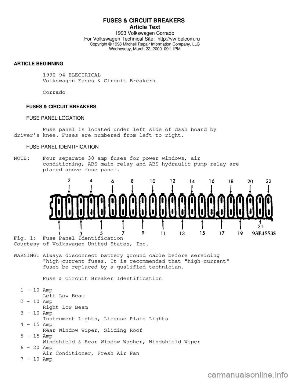
FUSE PANEL LOCATION
Fuse panel is located under left side of dash board by
driver's knee. Fuses are numbered from left to right.
FUSE PANEL IDENTIFICATION
NOTE: Four separate 30 amp fuses for power windows, air
conditioning, ABS main relay and ABS hydraulic pump relay are
placed above fuse panel.Fig. 1: Fuse Panel Identification
Courtesy of Volkswagen United States, Inc.
WARNING: Always disconnect battery ground cable before servicing
"high-current fuses. It is recommended that "high-current"
fuses be replaced by a qualified technician.
Fuse & Circuit Breaker Identification
1 - 10 Amp
Left Low Beam
2 - 10 Amp
Right Low Beam
3 - 10 Amp
Instrument Lights, License Plate Lights
4 - 15 Amp
Rear Window Wiper, Sliding Roof
5 - 15 Amp
Windshield & Rear Window Washer, Windshield Wiper
6 - 20 Amp
Air Conditioner, Fresh Air Fan
7 - 10 Amp
Page 580 of 920

FUSES & CIRCUIT BREAKERS
Article Text (p. 2)
1993 Volkswagen Corrado
For Volkswagen Technical Site: http://vw.belcom.ru
Copyright © 1998 Mitchell Repair Information Company, LLC
Wednesday, March 22, 2000 09:11PM
Right Tail & Side Lights
8 - 10 Amp
Left Tail & Side Lights
9 - 20 Amp
Rear Window & Mirror Heating
10 - 15 Amp
Foglights
11 - 10 Amp
Left High Beam, High Beam Indicator
12 - 10 Amp
Right High Beam
13 - 10 Amp
Horn, Radiator Fan
14 - 15 Amp
Back-Up Lights, Electric Mirrors, Heated Windshield Washer
Jets
15 - 10 Amp
Engine Electronic
16 - 15 Amp
Warning/Indicator Lights, Multi-Function Indicator, Glove Box
Light, Cassette Storage Light, Rear Spoiler
17 - 10 Amp
Turn Signals
18 - 20 Amp
Fuel Pump, Oxygen Sensor
19 - 30 Amp
Radiator Fan, Air Conditioner
20 - 10 Amp
Brakelights, Cruise Control
21 - 15 Amp
Dome & Luggage Compartment Lights, Cigarette Lighter, Central
Locking System, Multi-Function Indicator
22 - 10 Amp
Radio
CAUTIONS & WARNINGS
ELECTRICAL SHOCK
WARNING: Contact with live components of ignition system while
engine is running could lead to a fatal electric shock.
RADIATOR FAN
Keep hands away from radiator fan. Fan is controlled by a
thermostatic switch which may come on or run for up to 15 minutes even
after engine is turned off.
RADIATOR CAP
CAUTION: Always disconnect the fan motor when working near the
radiator fan. The fan is temperature controlled and could