display VOLKSWAGEN JETTA 1998 User Guide
[x] Cancel search | Manufacturer: VOLKSWAGEN, Model Year: 1998, Model line: JETTA, Model: VOLKSWAGEN JETTA 1998Pages: 339, PDF Size: 2.35 MB
Page 31 of 339
Downloaded from www.Manualslib.com manuals search engine 01-28
Diagnostic Trouble Code (DTC),
memory
All functions which could previously be
performed with V.A.G 1551 can also be
performed with the new tester VAS 5051.
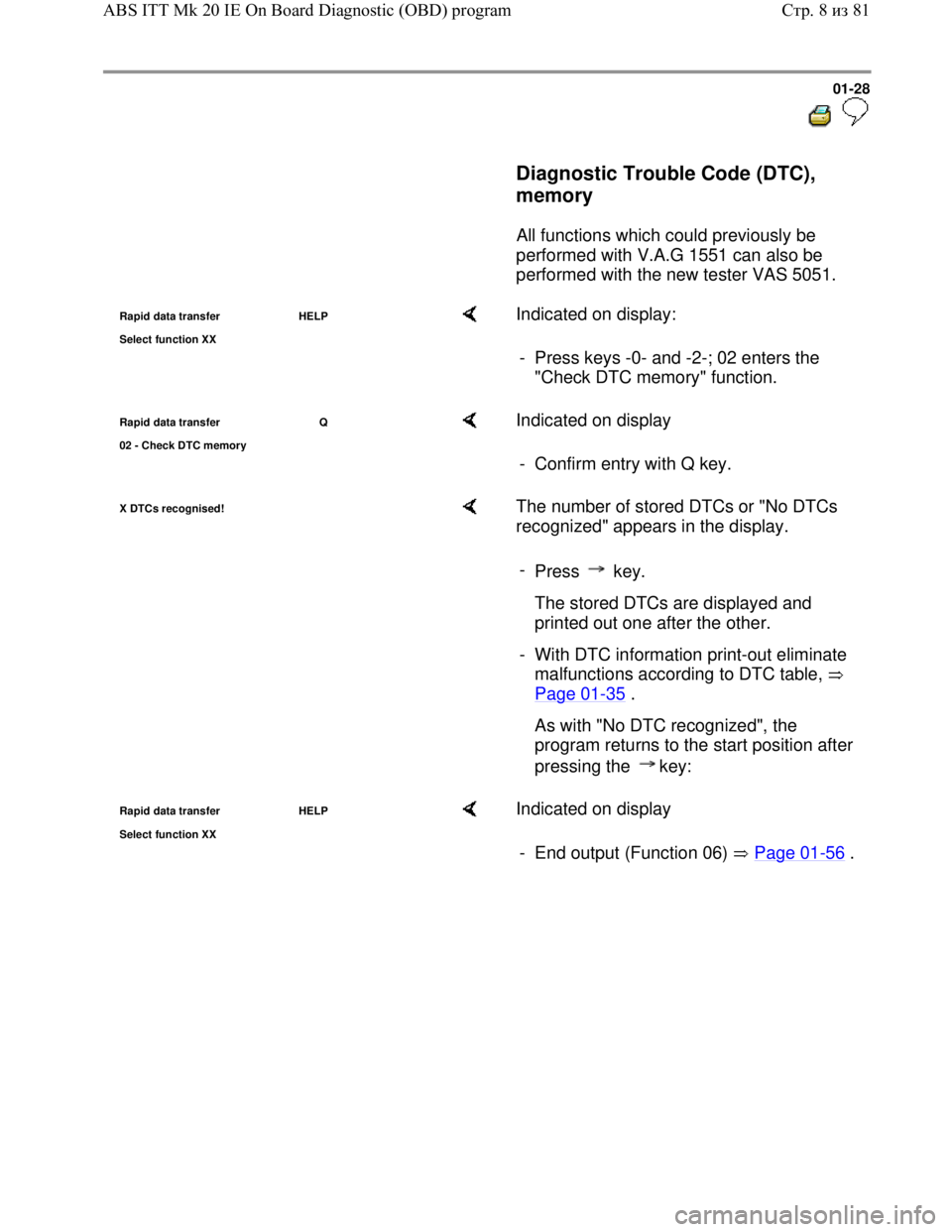
Rapid data transfer HELP
Select function XX Indicated on display:
- Press keys -0- and -2-; 02 enters the
"Check DTC memory" function.
Rapid data transfer Q
02 - Check DTC memor
y
Indicated on display
- Confirm entry with Q key.
X DTCs recognised! The number of stored DTCs or "No DTCs
recognized" appears in the display.
-
Press key.
The stored DTCs are displayed and
printed out one after the other.
- With DTC information print-out eliminate
malfunctions according to DTC table,
Page 01
-35 .
As with "No DTC recognized", the
program returns to the start position after
pressing the key:
Rapid data transfer HELP
Select function XX Indicated on display
- End output (Function 06) Page 01
-56 .
Стр. 8из 81 ABS ITT Mk 20 IE On Board Diagnostic (OBD) program
Page 33 of 339
Downloaded from www.Manualslib.com manuals search engine 01-30
Automatic test sequence
The automatic test sequence checks all the
Diagnostic Trouble Code (DTC) memories
of the control modules.
- Switch ignition on.
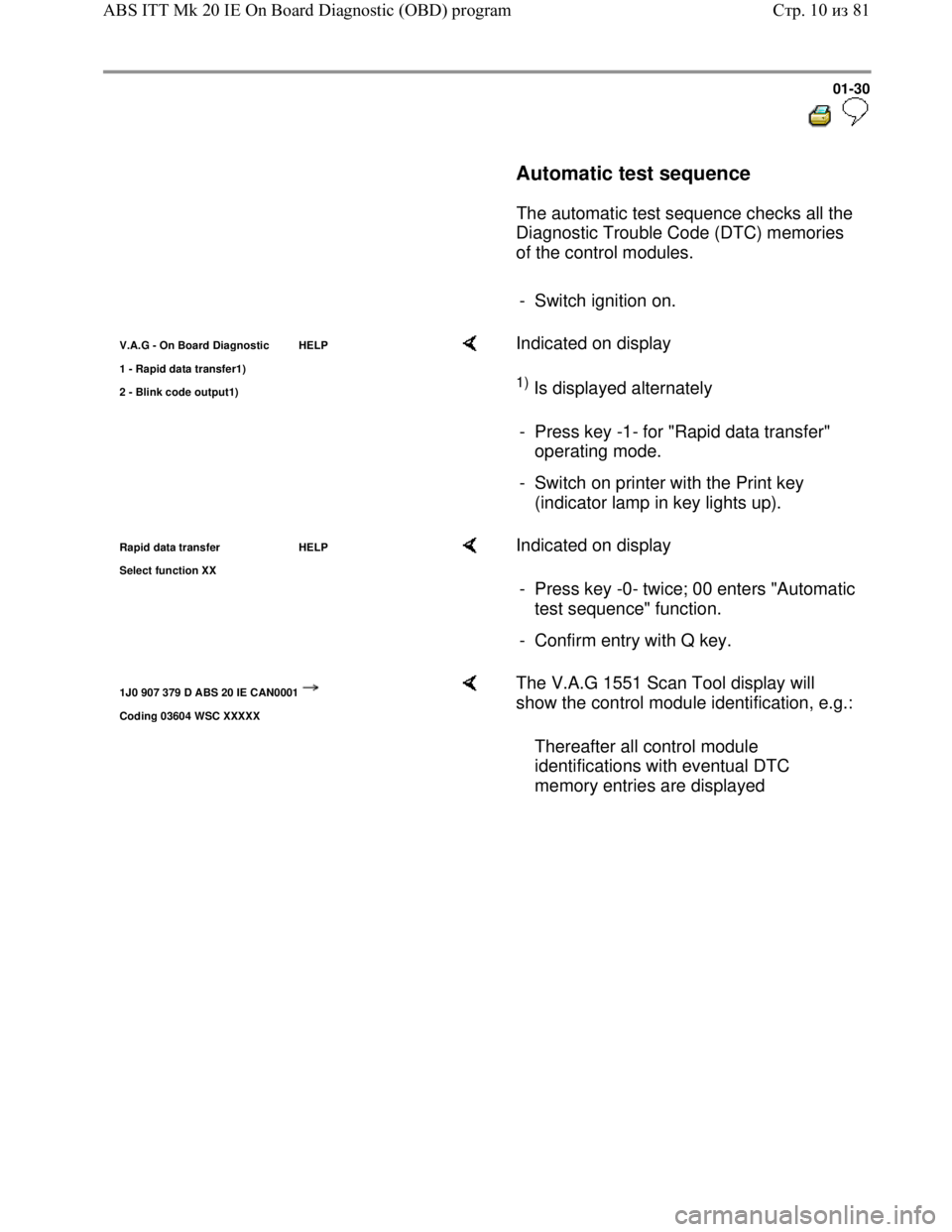
V.A.G - On Board Diagnostic HELP
1 - Ra
pid data transfer1)
2 - Blink code output1)
Indicated on display
1) Is displayed alternately
- Press key -1- for "Rapid data transfer"
operating mode.
- Switch on printer with the Print key
(indicator lamp in key lights up).
Rapid data transfer HELP
Select function XX Indicated on display
- Press key -0- twice; 00 enters "Automatic
test sequence" function.
- Confirm entry with Q key.
1J0 907 379 D ABS 20 IE CAN0001
Coding 03604 WSC XXXXX
The V.A.G 1551 Scan Tool display will
show the control module identification, e.g.:
Thereafter all control module
identifications with eventual DTC
memory entries are displayed
Стр. 10из 81 ABS ITT Mk 20 IE On Board Diagnostic (OBD) program
Page 35 of 339
Downloaded from www.Manualslib.com manuals search engine 01-32
Note:
The ABS function is switched off in the control
module during the On Board Diagnostic.
The DTC memory can be erased after
successful checking and repair.
Note:
Operating instructions for Vehicle Diagnosis,
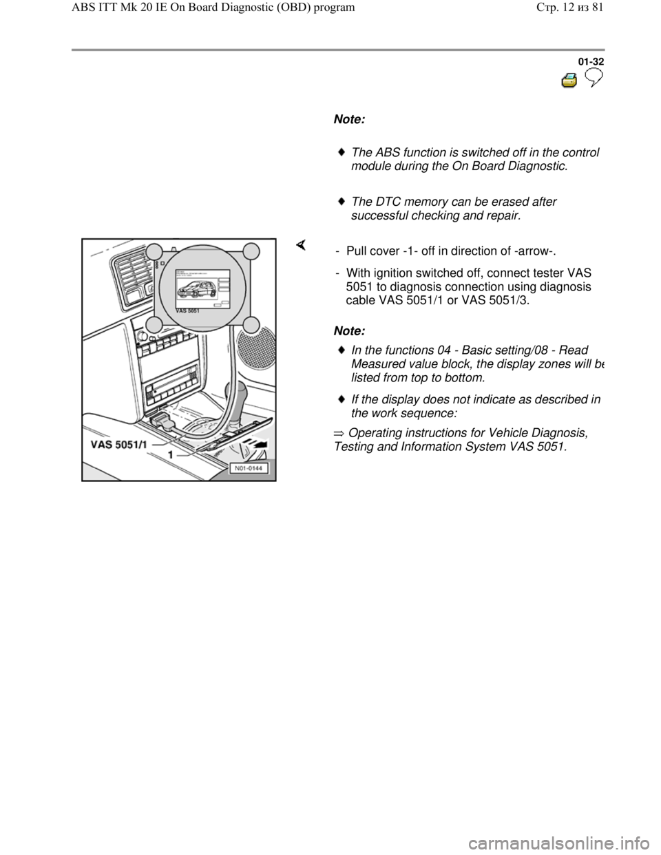
Testing and Information System VAS 5051. - Pull cover -1- off in direction of -arrow-.
- With ignition switched off, connect tester VAS
5051 to diagnosis connection using diagnosis
cable VAS 5051/1 or VAS 5051/3.
In the functions 04 - Basic setting/08 - Read
Measured value block, the display zones will b
e
listed from top to bottom.
If the display does not indicate as described in
the work sequence:
Стр. 12из 81 ABS ITT Mk 20 IE On Board Diagnostic (OBD) program
Page 36 of 339
Downloaded from www.Manualslib.com manuals search engine 01-33
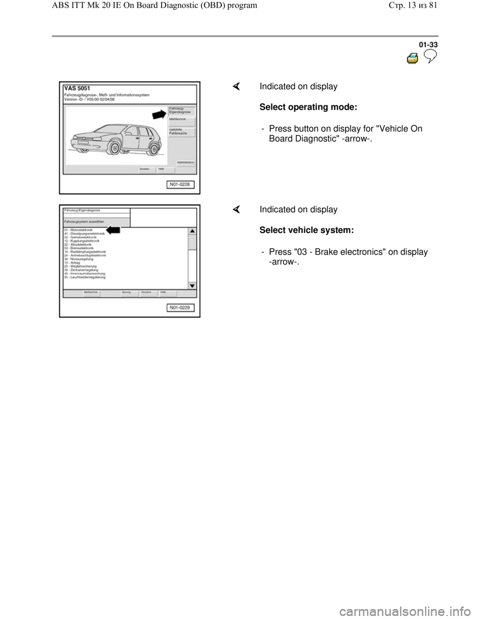
Indicated on display
Select operating mode:
- Press button on display for "Vehicle On
Board Diagnostic" -arrow-.
Indicated on display
Select vehicle system:
- Press "03 - Brake electronics" on display
-arrow-.
Стр. 13из 81 ABS ITT Mk 20 IE On Board Diagnostic (OBD) program
Page 37 of 339
Downloaded from www.Manualslib.com manuals search engine 01-34
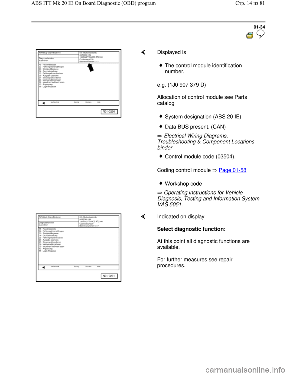
Displayed is
e.g. (1J0 907 379 D)
Allocation of control module see Parts
catalog
Electrical Wiring Diagrams,
Troubleshooting & Component Locations
binder
Coding control module Page 01
-58
Operating instructions for Vehicle
Diagnosis, Testing and Information System
VAS 5051.
The control module identification
number.
System designation (ABS 20 IE)
Data BUS present. (CAN)
Control module code (03504).
Workshop code
Indicated on display
Select diagnostic function:
At this point all diagnostic functions are
available.
For further measures see repair
procedures.
Стр. 14из 81 ABS ITT Mk 20 IE On Board Diagnostic (OBD) program
Page 39 of 339
Downloaded from www.Manualslib.com manuals search engine 01-36
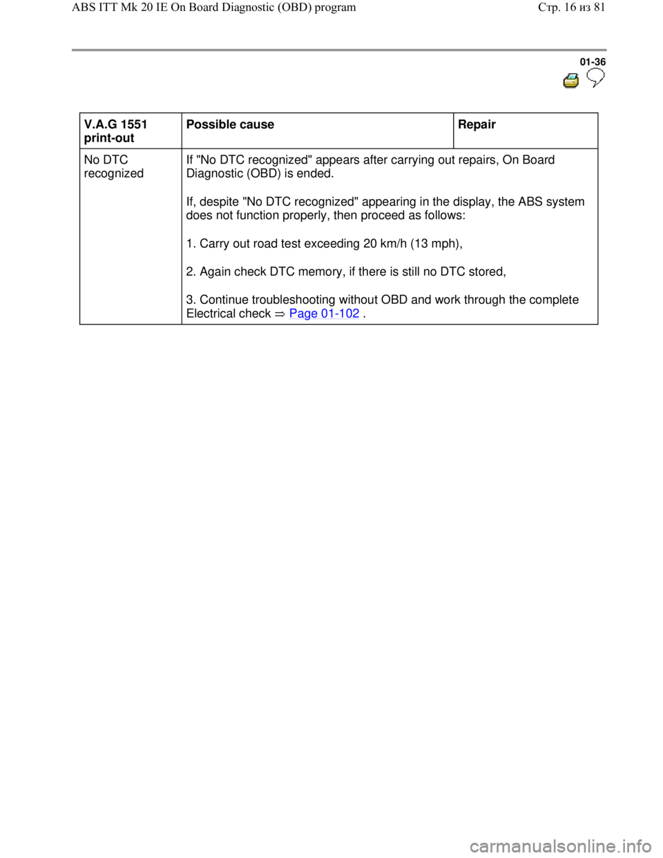
V.A.G 1551
print-out Possible cause
Repair
No DTC
recognized If "No DTC recognized" appears after carrying out repairs, On Board
Diagnostic (OBD) is ended.
If, despite "No DTC recognized" appearing in the display, the ABS system
does not function properly, then proceed as follows:
1. Carry out road test exceeding 20 km/h (13 mph),
2. Again check DTC memory, if there is still no DTC stored,
3. Continue troubleshooting without OBD and work through the complete
Electrical check Page 01
-102 .
Стр. 16из 81 ABS ITT Mk 20 IE On Board Diagnostic (OBD) program
Page 41 of 339
Downloaded from www.Manualslib.com manuals search engine 01-38
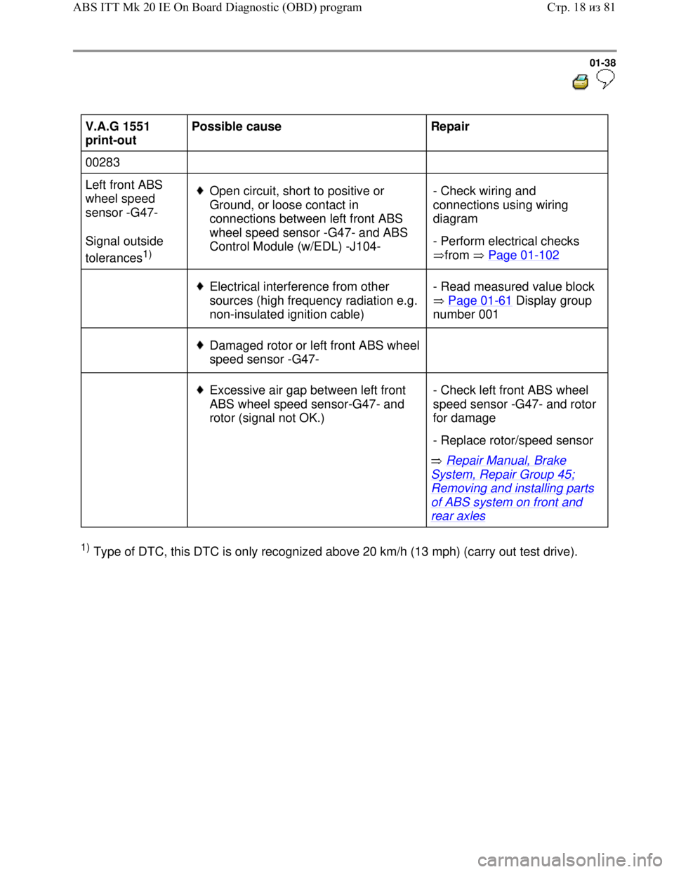
V.A.G 1551
print-out Possible cause
Repair
00283
Left front ABS
wheel speed
sensor -G47-
Signal outside
tolerances
1)
Open circuit, short to positive or
Ground, or loose contact in
connections between left front ABS
wheel speed sensor -G47- and ABS
Control Module (w/EDL) -J104- - Check wiring and
connections using wiring
diagram
- Perform electrical checks
from Page 01
-102
Electrical interference from other
sources (high frequency radiation e.g.
non-insulated ignition cable) - Read measured value block
Page 01
-61 Display group
number 001
Damaged rotor or left front ABS wheel
speed sensor -G47-
Excessive air gap between left front
ABS wheel speed sensor-G47- and
rotor (signal not OK.)
Repair Manual, Brake
System, Repair Group 45;
Removing and installing parts
of ABS system on front and
rear axles - Check left front ABS wheel
speed sensor -G47- and rotor
for damage
- Replace rotor/speed sensor
1) Type of DTC, this DTC is only recognized above 20 km/h (13 mph) (carry out test drive).
Стр. 18из 81 ABS ITT Mk 20 IE On Board Diagnostic (OBD) program
Page 42 of 339
Downloaded from www.Manualslib.com manuals search engine 01-39
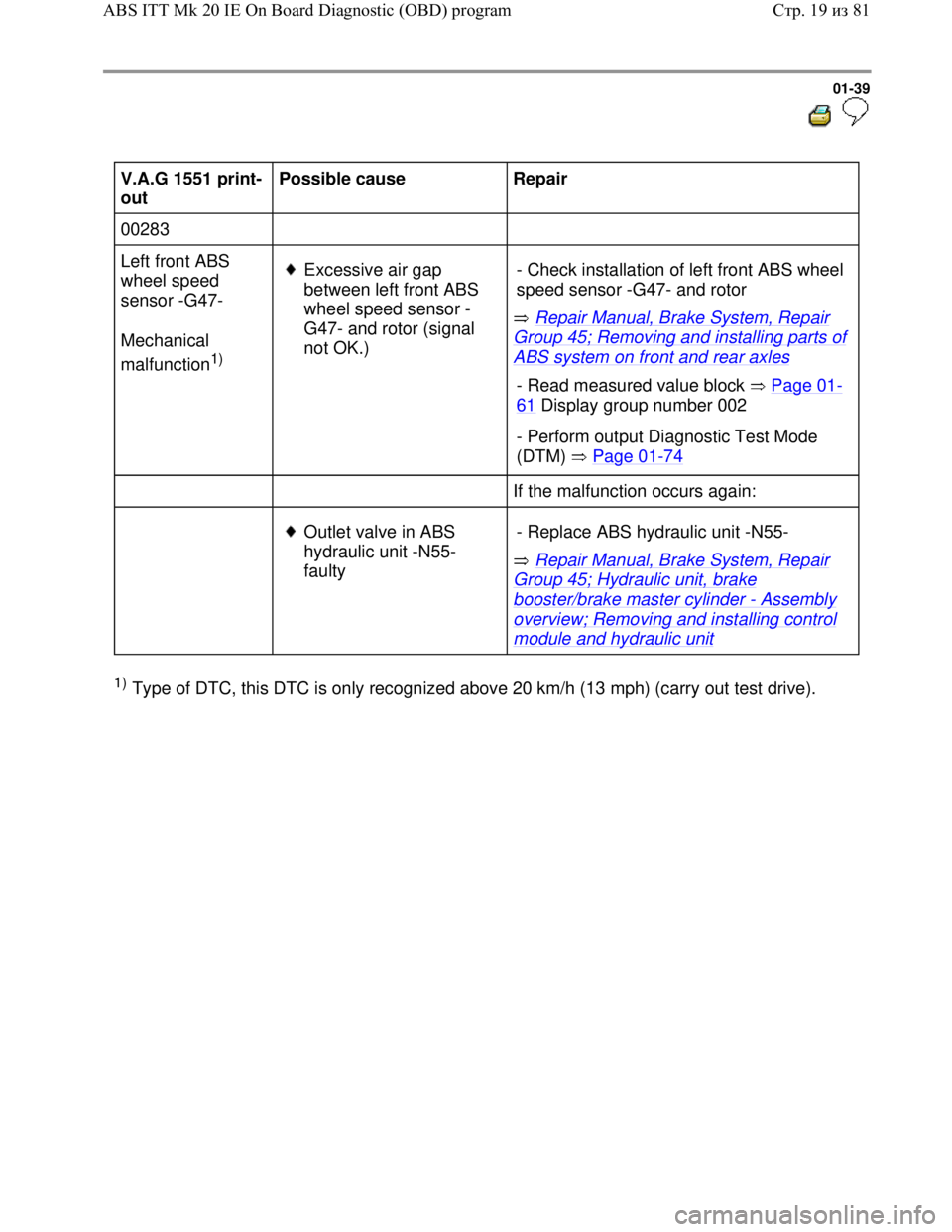
V.A.G 1551 print-
out Possible cause
Repair
00283
Left front ABS
wheel speed
sensor -G47-
Mechanical
malfunction
1)
Excessive air gap
between left front ABS
wheel speed sensor -
G47- and rotor (signal
not OK.) Repair Manual, Brake System, Repair
Group 45; Removing and installing parts of
ABS system on front and rear axles - Check installation of left front ABS wheel
speed sensor -G47- and rotor
- Read measured value block Page 01-
61 Display group number 002
- Perform output Diagnostic Test Mode
(DTM) Page 01
-74
If the malfunction occurs again:
Outlet valve in ABS
hydraulic unit -N55-
faulty Repair Manual, Brake System, Repair
Group 45; Hydraulic unit, brake
booster/brake master cylinder - Assembly
overview; Removing and installing control
module and hydraulic unit - Replace ABS hydraulic unit -N55-
1) Type of DTC, this DTC is only recognized above 20 km/h (13 mph) (carry out test drive).
Стр. 19из 81 ABS ITT Mk 20 IE On Board Diagnostic (OBD) program
Page 44 of 339
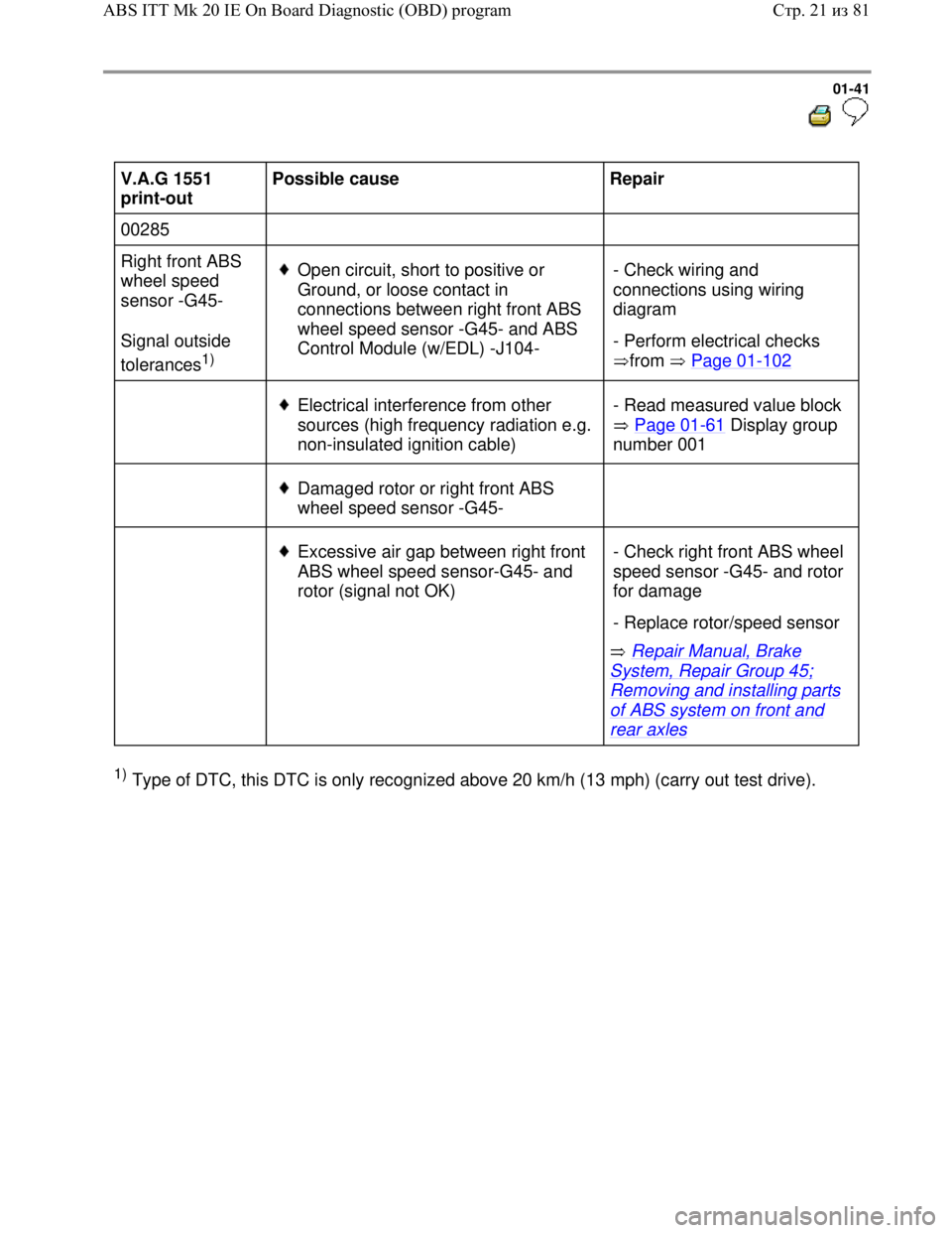
Downloaded from www.Manualslib.com manuals search engine 01-41
V.A.G 1551
print-out Possible cause
Repair
00285
Right front ABS
wheel speed
sensor -G45-
Signal outside
tolerances
1)
Open circuit, short to positive or
Ground, or loose contact in
connections between right front ABS
wheel speed sensor -G45- and ABS
Control Module (w/EDL) -J104- - Check wiring and
connections using wiring
diagram
- Perform electrical checks
from Page 01
-102
Electrical interference from other
sources (high frequency radiation e.g.
non-insulated ignition cable) - Read measured value block
Page 01
-61 Display group
number 001
Damaged rotor or right front ABS
wheel speed sensor -G45-
Excessive air gap between right front
ABS wheel speed sensor-G45- and
rotor (signal not OK)
Repair Manual, Brake
System, Repair Group 45;
Removing and installing parts
of ABS system on front and
rear axles - Check right front ABS wheel
speed sensor -G45- and rotor
for damage
- Replace rotor/speed sensor
1) Type of DTC, this DTC is only recognized above 20 km/h (13 mph) (carry out test drive).
Стр. 21из 81 ABS ITT Mk 20 IE On Board Diagnostic (OBD) program
Page 45 of 339
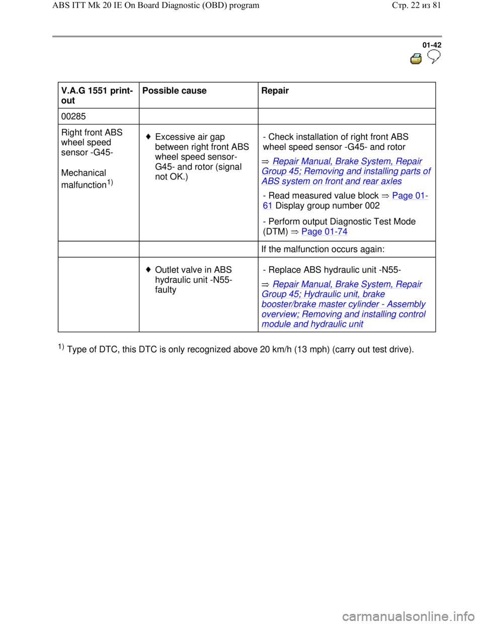
Downloaded from www.Manualslib.com manuals search engine 01-42
V.A.G 1551 print-
out Possible cause
Repair
00285
Right front ABS
wheel speed
sensor -G45-
Mechanical
malfunction
1)
Excessive air gap
between right front ABS
wheel speed sensor-
G45- and rotor (signal
not OK.) Repair Manual, Brake System, Repair
Group 45; Removing and installing parts of
ABS system on front and rear axles - Check installation of right front ABS
wheel speed sensor -G45- and rotor
- Read measured value block Page 01-
61 Display group number 002
- Perform output Diagnostic Test Mode
(DTM) Page 01
-74
If the malfunction occurs again:
Outlet valve in ABS
hydraulic unit -N55-
faulty Repair Manual, Brake System, Repair
Group 45; Hydraulic unit, brake
booster/brake master cylinder - Assembly
overview; Removing and installing control
module and hydraulic unit - Replace ABS hydraulic unit -N55-
1) Type of DTC, this DTC is only recognized above 20 km/h (13 mph) (carry out test drive).
Стр. 22из 81 ABS ITT Mk 20 IE On Board Diagnostic (OBD) program