battery VOLKSWAGEN JETTA 1998 Service Manual
[x] Cancel search | Manufacturer: VOLKSWAGEN, Model Year: 1998, Model line: JETTA, Model: VOLKSWAGEN JETTA 1998Pages: 339, PDF Size: 2.35 MB
Page 2 of 339
Downloaded from www.Manualslib.com manuals search engine 01-1
ABS ITT Mark 20 IE On Board
Diagnostic (OBD)
Function
Since the control modules are interconnected
with CAN-bus, always begin OBD by checking
the Diagnostic Trouble Code (DTC) memories
of all the control modules in the vehicle.
This occurs in the Automatic test sequence and
is activated with key function 00.
When doing this, check to see if there are
DTCs stored which may influence the ABS.
On Board Diagnostic (OBD) relates to the
electrical/electronic part of the ABS, i.e. only
malfunctions via the electrical connection to the
control module are recognized (e.g. speed
sensor open circuit).
The 25-pin ABS Control Module (w/EDL) -J104-
forms with the hydraulic unit a compact unit.
The unit is located on the left in the engine
compartment. The control module is equipped
with a DTC memory. The diagnostic connection
is located in the center console below the
heating/air conditioning controls.
The control module recognizes malfunctions
during vehicle operation and stores them in a
permanent memory, the contents of which
remain even during periods of no battery
voltage.
Стр. 1из 8 ABS ITT Mark 20 IE On Board Diagnostic (OBD)
Page 78 of 339
Downloaded from www.Manualslib.com manuals search engine 01-75
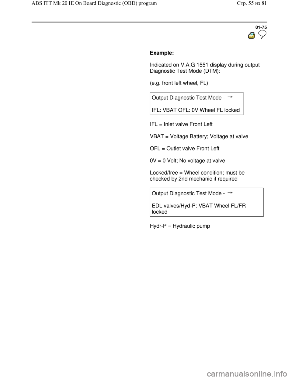
Example:
Indicated on V.A.G 1551 display during output
Diagnostic Test Mode (DTM):
(e.g. front left wheel, FL)
Output Diagnostic Test Mode -
IFL: VBAT OFL: 0V Wheel FL locked
IFL = Inlet valve Front Left
VBAT = Voltage Battery; Voltage at valve
OFL = Outlet valve Front Left
0V = 0 Volt; No voltage at valve
Locked/free = Wheel condition; must be
checked by 2nd mechanic if required
Output Diagnostic Test Mode -
EDL valves/Hyd-P: VBAT Wheel FL/FR
locked
Hydr-P = Hydraulic pump
Стр. 55из 81 ABS ITT Mk 20 IE On Board Diagnostic (OBD) program
Page 110 of 339
Downloaded from www.Manualslib.com manuals search engine
01-107
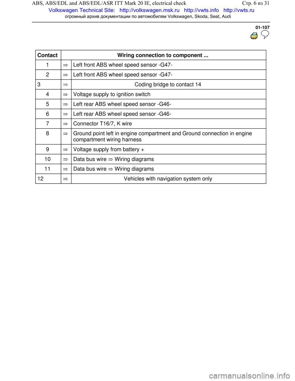
Contact
Wiring connection to component ...
1
Left front ABS wheel s peed sensor -G47-
2
Left front ABS wheel s peed sensor -G47-
3
Coding bridge to contact 14
4
Voltage supply to ignition switch
5
Left rear ABS wheel speed sensor -G46-
6
Left rear ABS wheel speed sensor -G46-
7
Connector T16/7, K wire
8
Ground point left in engi ne compartment and Ground connection in engine
compartment wiring harness
9
Voltage supply fr om battery +
10
Data bus wire Wiring diagrams
11 Data bus wire Wiring diagrams
12 Vehicles with navi gation system only
Стр. 6из 31
ABS, ABS/EDL and ABS/EDL/ASR I TT Mark 20 IE, electrical check
Volkswagen Technical Site: http://v olkswagen.msk.ru http://vwts.info http://vwts.ru
огромный архив документации по автомобилям Volkswagen, Skoda, Seat, Audi
Page 111 of 339
Downloaded from www.Manualslib.com manuals search engine 01-108
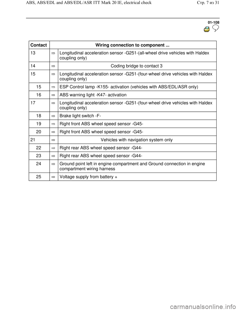
Contact
Wiring connection to component ...
13
Longitudinal acceleration sensor -G251-(all-wheel drive vehicles with Haldex
coupling only)
14
Coding bridge to contact 3
15
Longitudinal acceleration sensor -G251-(four-wheel drive vehicles with Haldex
coupling only)
15
ESP Control lamp -K155- activation (vehicles with ABS/EDL/ASR only)
16
ABS warning light -K47- activation
17
Longitudinal acceleration sensor -G251-(four-wheel drive vehicles with Haldex
coupling only)
18
Brake light switch -F-
19
Right front ABS wheel speed sensor -G45-
20
Right front ABS wheel speed sensor -G45-
21
Vehicles with navigation system only
22
Right rear ABS wheel speed sensor -G44-
23
Right rear ABS wheel speed sensor -G44-
24
Ground point left in engine compartment and Ground connection in engine
compartment wiring harness
25
Voltage supply from battery +
Стр. 7из 31 ABS, ABS/EDL and ABS/EDL/ASR ITT Mark 20 IE, electrical check
Page 116 of 339
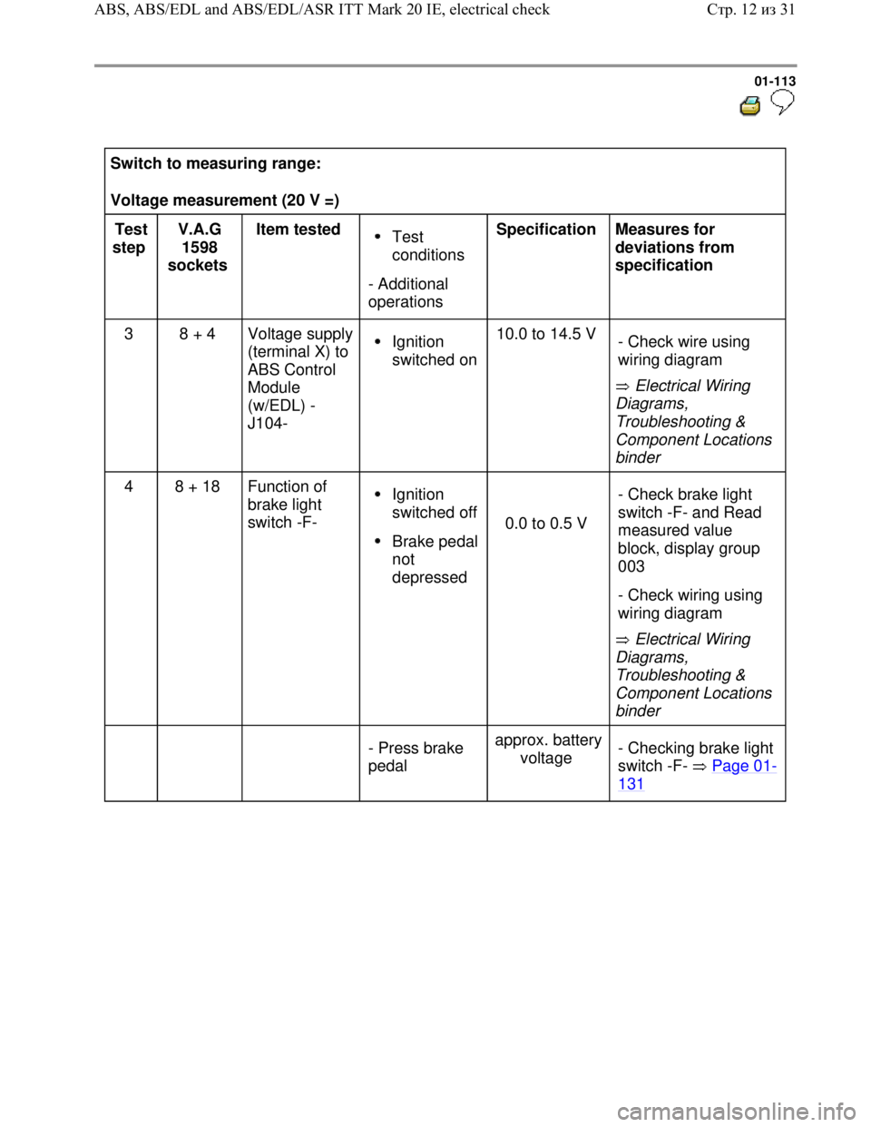
Downloaded from www.Manualslib.com manuals search engine 01-113
Switch to measuring range:
Voltage measurement (20 V =)
Test
step V.A.G
1598
sockets Item tested
Test
conditions
- Additional
operations Specification
Measures for
deviations from
specification
3 8 + 4 Voltage supply
(terminal X) to
ABS Control
Module
(w/EDL) -
J104-
Ignition
switched on10.0 to 14.5 V
Electrical Wiring
Diagrams,
Troubleshooting &
Component Locations
binder - Check wire using
wiring diagram
4 8 + 18 Function of
brake light
switch -F- Ignition
switched off
Brake pedal
not
depressed
0.0 to 0.5 V
Electrical Wiring
Diagrams,
Troubleshooting &
Component Locations
binder - Check brake light
switch -F- and Read
measured value
block, display group
003
- Check wiring using
wiring diagram
- Press brake
pedal approx. battery
voltage - Checking brake light
switch -F- Page 01
-
131
Стр. 12из 31 ABS, ABS/EDL and ABS/EDL/ASR ITT Mark 20 IE, electrical check
Page 128 of 339
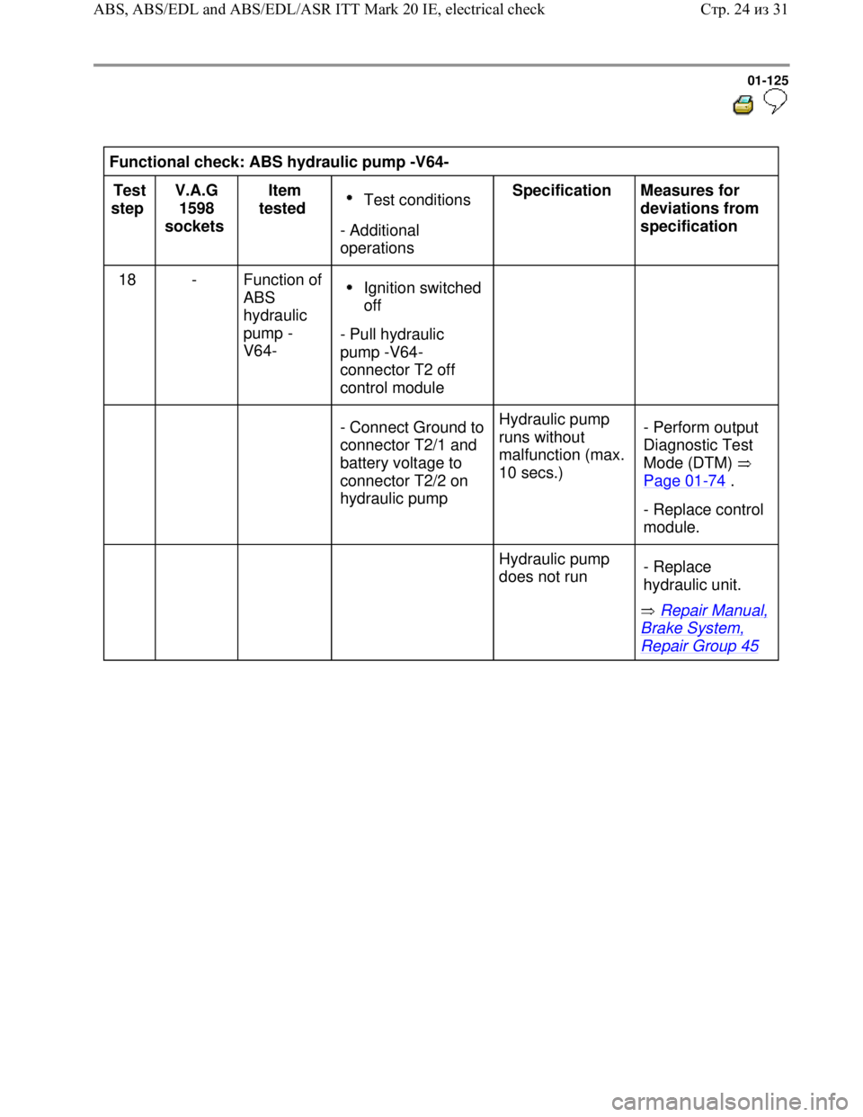
Downloaded from www.Manualslib.com manuals search engine 01-125
Functional check: ABS hydraulic pump -V64-
Test
step V.A.G
1598
sockets Item
tested
Test conditions
- Additional
operations Specification
Measures for
deviations from
specification
18 - Function of
ABS
hydraulic
pump -
V64-
Ignition switched
off
- Pull hydraulic
pump -V64-
connector T2 off
control module
- Connect Ground to
connector T2/1 and
battery voltage to
connector T2/2 on
hydraulic pump Hydraulic pump
runs without
malfunction (max.
10 secs.) - Perform output
Diagnostic Test
Mode (DTM)
Page 01
-74 .
- Replace control
module.
Hydraulic pump
does not run
Repair Manual,
Brake System,
Repair Group 45 - Replace
hydraulic unit.
Стр. 24из 31 ABS, ABS/EDL and ABS/EDL/ASR ITT Mark 20 IE, electrical check
Page 137 of 339
Downloaded from www.Manualslib.com manuals search engine 01-134
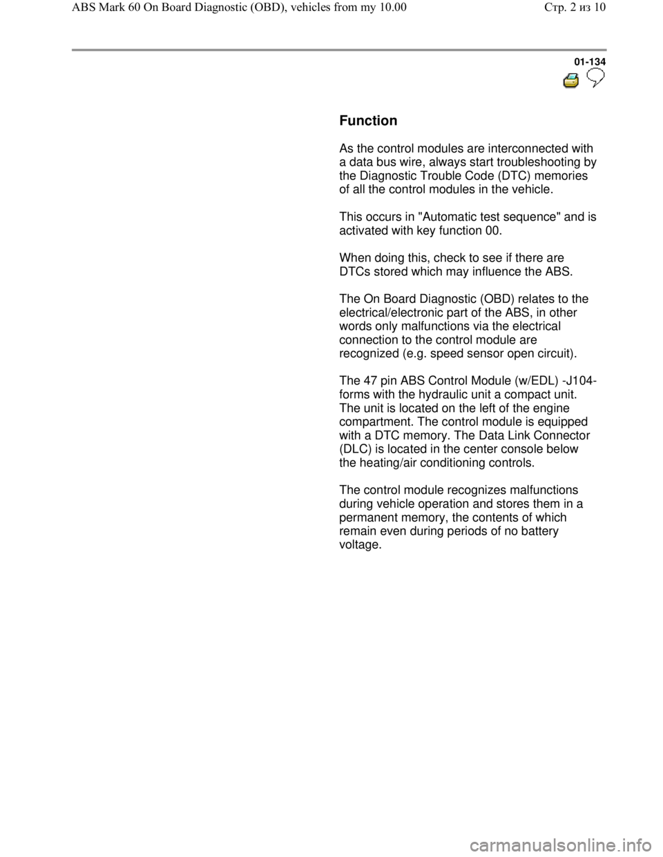
Function
As the control modules are interconnected with
a data bus wire, always start troubleshooting by
the Diagnostic Trouble Code (DTC) memories
of all the control modules in the vehicle.
This occurs in "Automatic test sequence" and is
activated with key function 00.
When doing this, check to see if there are
DTCs stored which may influence the ABS.
The On Board Diagnostic (OBD) relates to the
electrical/electronic part of the ABS, in other
words only malfunctions via the electrical
connection to the control module are
recognized (e.g. speed sensor open circuit).
The 47 pin ABS Control Module (w/EDL) -J104-
forms with the hydraulic unit a compact unit.
The unit is located on the left of the engine
compartment. The control module is equipped
with a DTC memory. The Data Link Connector
(DLC) is located in the center console below
the heating/air conditioning controls.
The control module recognizes malfunctions
during vehicle operation and stores them in a
permanent memory, the contents of which
remain even during periods of no battery
voltage.
Стр. 2из 10 ABS Mark 60 On Board Diagnostic (OBD), vehicles from my 10.00
Page 181 of 339
Downloaded from www.Manualslib.com manuals search engine 01-173
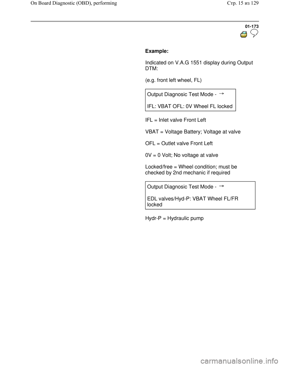
Example:
Indicated on V.A.G 1551 display during Output
DTM:
(e.g. front left wheel, FL)
Output Diagnosic Test Mode -
IFL: VBAT OFL: 0V Wheel FL locked
IFL = Inlet valve Front Left
VBAT = Voltage Battery; Voltage at valve
OFL = Outlet valve Front Left
0V = 0 Volt; No voltage at valve
Locked/free = Wheel condition; must be
checked by 2nd mechanic if required
Output Diagnosic Test Mode -
EDL valves/Hyd-P: VBAT Wheel FL/FR
locked
Hydr-P = Hydraulic pump
Стр. 15из 129 On Board Diagnostic (OBD), performing
Page 223 of 339
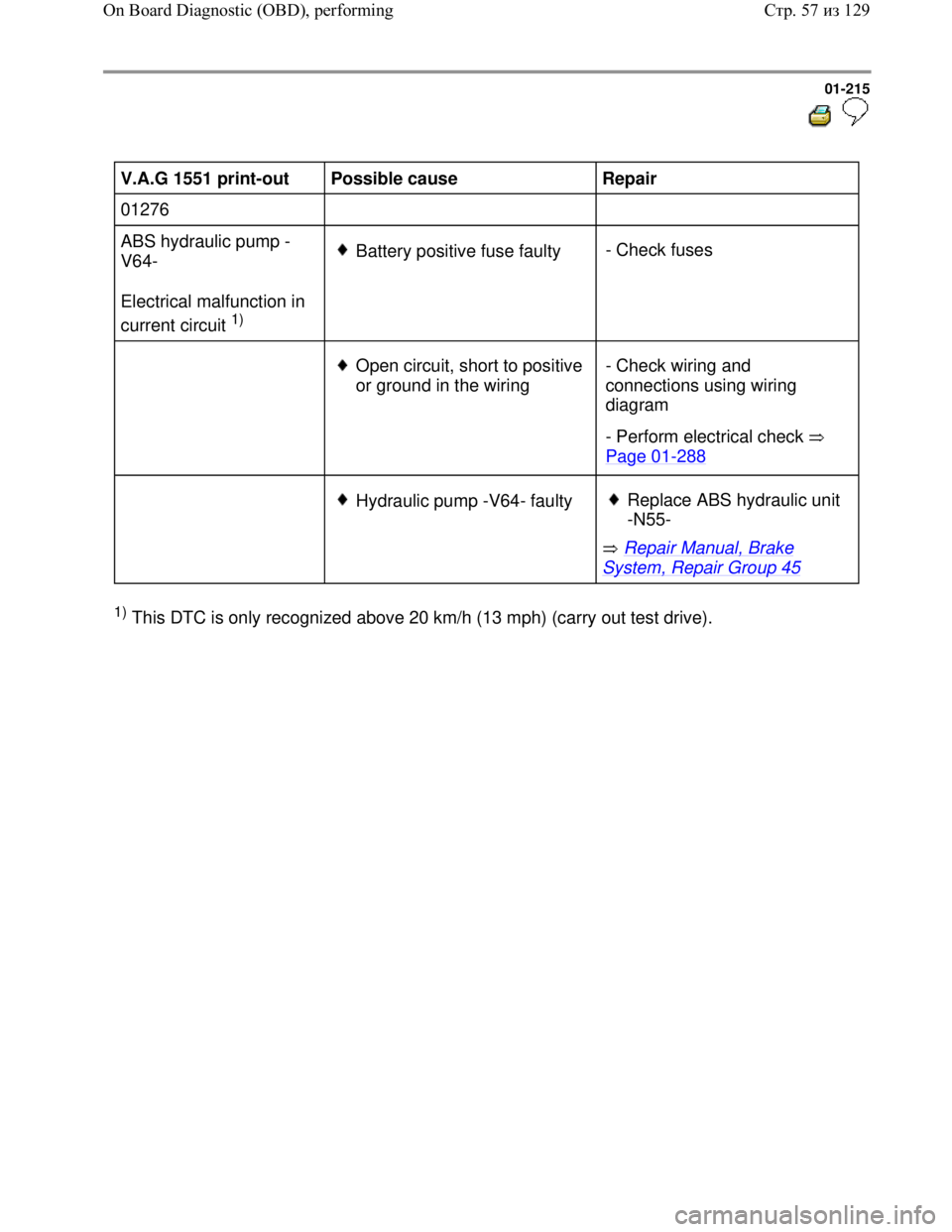
Downloaded from www.Manualslib.com manuals search engine 01-215
V.A.G 1551 print-out
Possible cause
Repair
01276
ABS hydraulic pump -
V64-
Electrical malfunction in
current circuit
1)
Battery positive fuse faulty- Check fuses
Open circuit, short to positive
or ground in the wiring - Check wiring and
connections using wiring
diagram
- Perform electrical check
Page 01
-288
Hydraulic pump -V64- faulty
Repair Manual, Brake
System, Repair Group 45
Replace ABS hydraulic unit
-N55-
1) This DTC is only recognized above 20 km/h (13 mph) (carry out test drive).
Стр. 57из 129 On Board Diagnostic (OBD), performing
Page 301 of 339
Downloaded from www.Manualslib.com manuals search engine
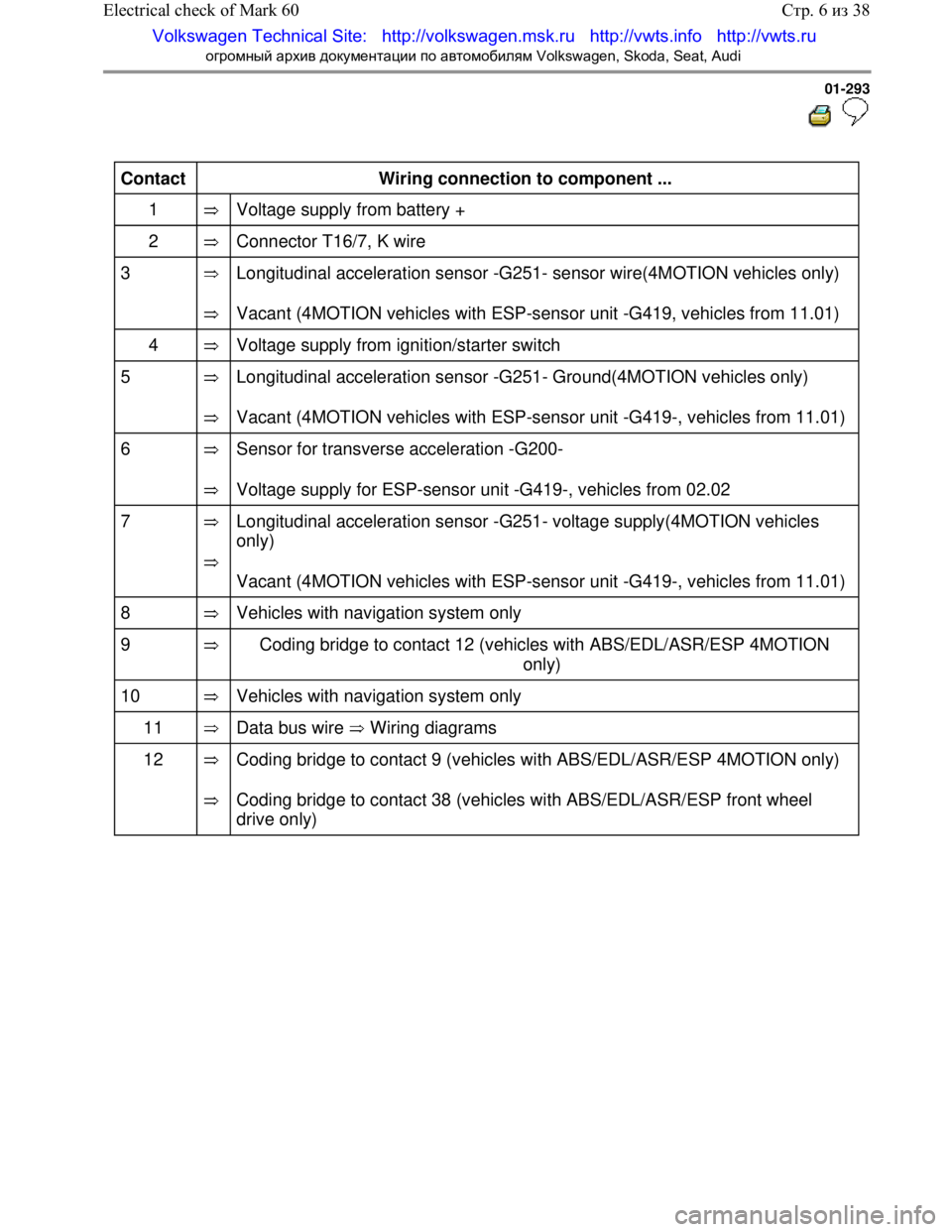
01-293
Contact
Wiring connection to component ...
1
Voltage supply fr om battery +
2
Connector T16/7, K wire
3
Longitudinal acceleration sens or -G251- sensor wire(4MOTION vehicles only)
Vacant (4MOTION vehicles with ESP-sensor unit -G419, vehicles from 11.01)
4
Voltage supply from igni tion/starter switch
5
Longitudinal acceleration se nsor -G251- Ground(4MOTION vehicles only)
Vacant (4MOTION vehicles with ESP-sensor unit -G419- , vehicles from 11.01)
6
Sensor for transverse acceleration -G200-
Voltage supply for ESP-sensor unit -G419-, vehicles from 02.02
7
Longitudinal acceleration se nsor -G251- voltage supply(4MOTION vehicles
only)
Vacant (4MOTION vehicles with ESP-sensor unit -G419- , vehicles from 11.01)
8
Vehicles with navi gation system only
9
Coding bridge to contact 12 (vehicle s with ABS/EDL/ASR/ESP 4MOTION
only)
10
Vehicles with navi gation system only
11
Data bus wire Wiring diagrams
12
Coding bridge to contact 9 (vehicles with ABS/EDL/ASR/ESP 4MOTION only)
Coding bridge to contact 38 (vehicles with ABS/EDL/ASR/ESP front wheel
drive only)
Стр. 6 из 38
Electrical check of Mark 60
Volkswagen Technical Site: http://v olkswagen.msk.ru http://vwts.info http://vwts.ru
огромный архив документации по автомобилям Volkswagen, Skoda, Seat, Audi