engine VOLKSWAGEN JETTA 1998 Service Manual
[x] Cancel search | Manufacturer: VOLKSWAGEN, Model Year: 1998, Model line: JETTA, Model: VOLKSWAGEN JETTA 1998Pages: 339, PDF Size: 2.35 MB
Page 291 of 339
Downloaded from www.Manualslib.com manuals search engine 01-283
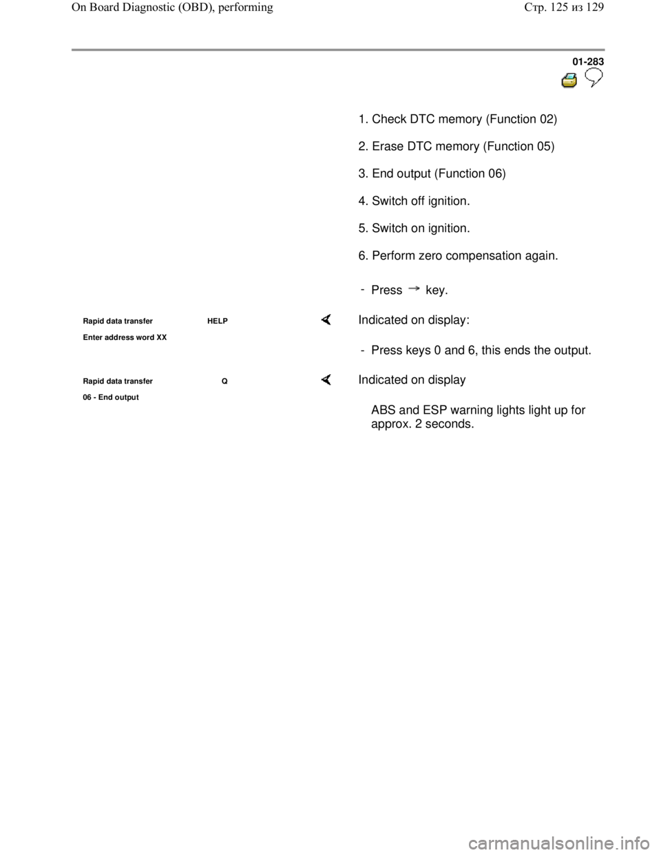
1. Check DTC memory (Function 02)
2. Erase DTC memory (Function 05)
3. End output (Function 06)
4. Switch off ignition.
5. Switch on ignition.
6. Perform zero compensation again.
-
Press key.
Rapid data transfer HELP
Enter address word XX Indicated on display:
- Press keys 0 and 6, this ends the output.
Rapid data transfer Q
06 - End output Indicated on display
ABS and ESP warning lights light up for
approx. 2 seconds.
Стр. 125из 129 On Board Diagnostic (OBD), performing
Page 292 of 339
Downloaded from www.Manualslib.com manuals search engine 01-284
Display group number 93: activation of ESP
driving test
The ESP driving test is used to check the
plausibility of the signals from sensor for
transverse acceleration -G200-, sender for
rotation rate -G202- and sender 1 for brake
booster -G201-.
The ESP driving test should be performed each
time parts of the ESP system are removed or
replaced.
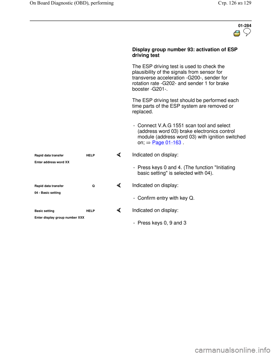
- Connect V.A.G 1551 scan tool and select
(address word 03) brake electronics control
module (address word 03) with ignition switched
on; Page 01
-163 .
Rapid data transfer HELP
Enter address word XX Indicated on display:
- Press keys 0 and 4. (The function "Initiating
basic setting" is selected with 04).
Rapid data transfer Q
04 - Basic settin
g
Indicated on display:
- Confirm entry with key Q.
Basic setting HELP
Enter displa
y group number XXX
Indicated on display:
- Press keys 0, 9 and 3
Стр. 126из 129 On Board Diagnostic (OBD), performing
Page 293 of 339
Downloaded from www.Manualslib.com manuals search engine 01-285
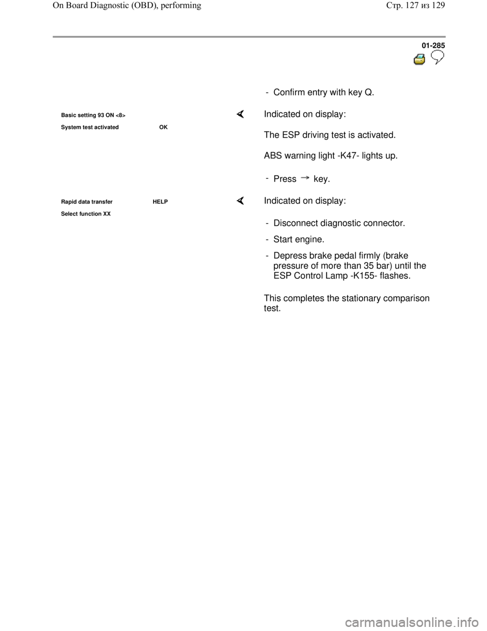
- Confirm entry with key Q.
Basic setting 93 ON <8>
S
ystem test activated OK
Indicated on display:
The ESP driving test is activated.
ABS warning light -K47- lights up.
-
Press key.
Rapid data transfer HELP
Select function XX Indicated on display:
This completes the stationary comparison
test. - Disconnect diagnostic connector.
- Start engine.
- Depress brake pedal firmly (brake
pressure of more than 35 bar) until the
ESP Control Lamp -K155- flashes.
Стр. 127из 129 On Board Diagnostic (OBD), performing
Page 294 of 339
Downloaded from www.Manualslib.com manuals search engine 01-286
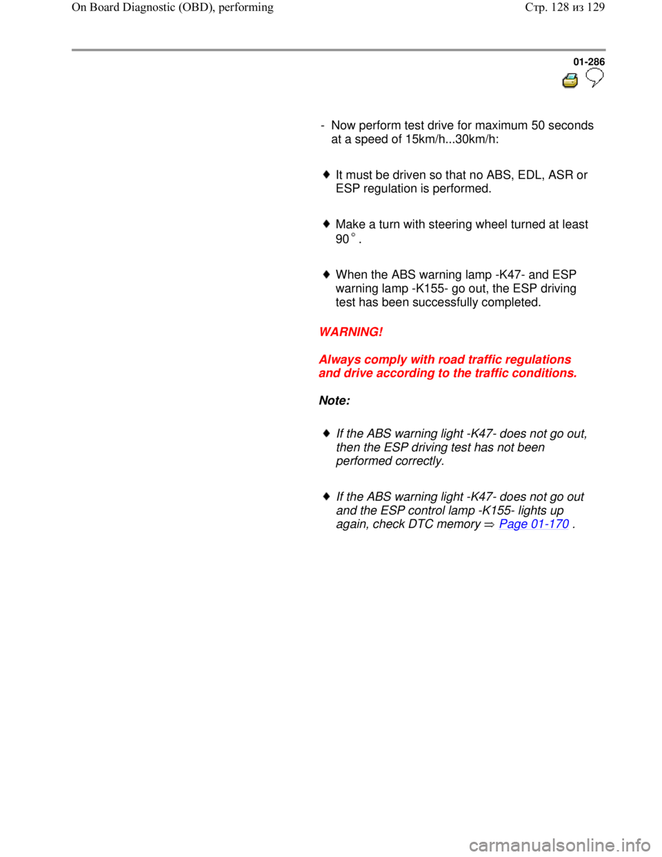
- Now perform test drive for maximum 50 seconds
at a speed of 15km/h...30km/h:
It must be driven so that no ABS, EDL, ASR or
ESP regulation is performed.
Make a turn with steering wheel turned at least
90 .
When the ABS warning lamp -K47- and ESP
warning lamp -K155- go out, the ESP driving
test has been successfully completed.
WARNING!
Always comply with road traffic regulations
and drive according to the traffic conditions.
Note:
If the ABS warning light -K47- does not go out,
then the ESP driving test has not been
performed correctly.
If the ABS warning light -K47- does not go out
and the ESP control lamp -K155- lights up
again, check DTC memory Page 01
-170 .
Стр. 128из 129 On Board Diagnostic (OBD), performing
Page 295 of 339
Downloaded from www.Manualslib.com manuals search engine 01-287
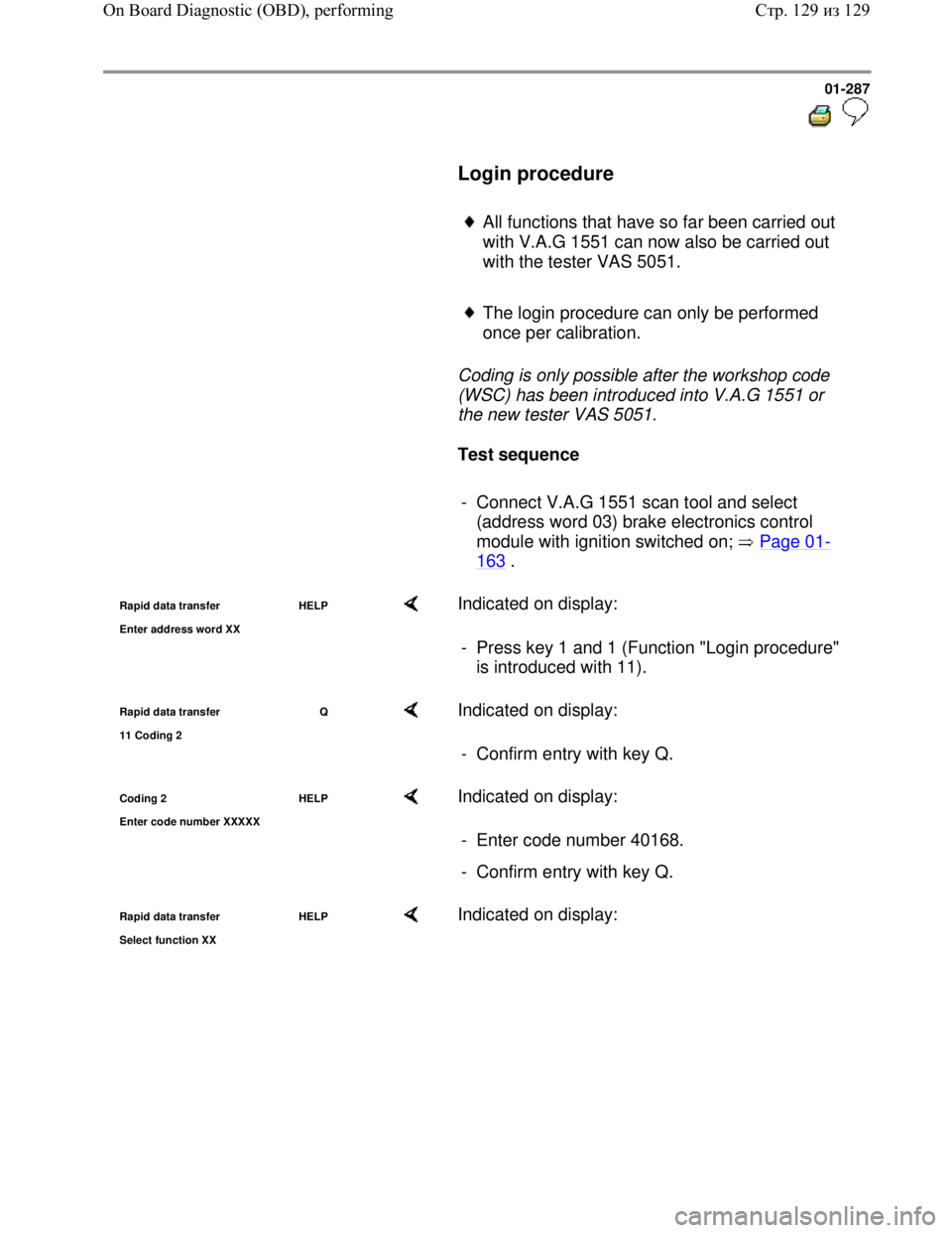
Login procedure
All functions that have so far been carried out
with V.A.G 1551 can now also be carried out
with the tester VAS 5051.
The login procedure can only be performed
once per calibration.
Coding is only possible after the workshop code
(WSC) has been introduced into V.A.G 1551 or
the new tester VAS 5051.
Test sequence
- Connect V.A.G 1551 scan tool and select
(address word 03) brake electronics control
module with ignition switched on; Page 01
-
163 .
Rapid data transfer HELP
Enter address word XX Indicated on display:
- Press key 1 and 1 (Function "Login procedure"
is introduced with 11).
Rapid data transfer Q
11 Codin
g 2
Indicated on display:
- Confirm entry with key Q.
Coding 2 HELP
Enter code number XXXXX Indicated on display:
- Enter code number 40168.
- Confirm entry with key Q.
Rapid data transfer HELP
Select function XX Indicated on display:
Стр. 129из 129 On Board Diagnostic (OBD), performing
Page 296 of 339
Downloaded from www.Manualslib.com manuals search engine 01-288
Electrical
check of
Mark 60
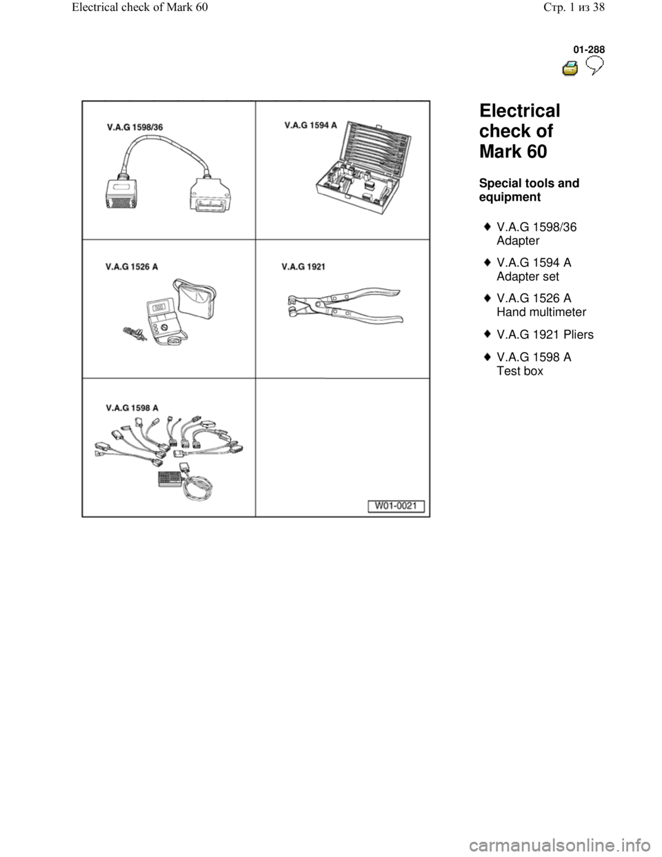
Special tools and
equipment
V.A.G 1598/36
Adapter
V.A.G 1594 A
Adapter set
V.A.G 1526 A
Hand multimeter
V.A.G 1921 Pliers
V.A.G 1598 A
Test box
Стр. 1из 38 Electrical check of Mark 60
Page 297 of 339
Downloaded from www.Manualslib.com manuals search engine 01-289
The test steps Page 01-297 apply only to
vehicles with ABS/EDL/ASR/ESP
For vehicles on which the On Board Diagnostic
(OBD) does not give any indication of the
source of the malfunction. Work through the
complete electrical check.
For vehicles on which the OBD provides a
direct indication of the source of the
malfunction. Only carry out the test steps
recommended in the DTC table (directed entry).
An overview of all the test steps in the electrical
check Page 01
-297 .
Стр. 2из 38 Electrical check of Mark 60
Page 298 of 339

Downloaded from www.Manualslib.com manuals search engine 01-290
Test prerequisites
Switch ignition and electrical
consumers off before commencing the
check (headlights, lighting, fans ...).
Fuses must be OK (remove fuses from
fuse holder to check).
Electrical Wiring Diagrams,
Troubleshooting & Component
Locationsbinder
- Pull fuse holder out of cable channel.
- Release ABS Control Module (w/EDL) -
J104- connector -arrow 1- and pull off -
arrow 2-.
Стр. 3из 38 Electrical check of Mark 60
Page 299 of 339
Downloaded from www.Manualslib.com manuals search engine 01-291
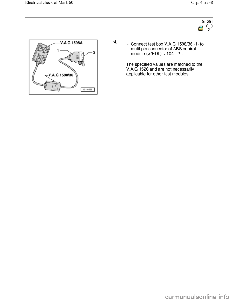
The specified values are matched to the
V.A.G 1526 and are not necessarily
applicable for other test modules. - Connect test box V.A.G 1598/36 -1- to
multi-pin connector of ABS control
module (w/EDL) -J104- -2-.
Стр. 4из 38 Electrical check of Mark 60
Page 300 of 339
Downloaded from www.Manualslib.com manuals search engine 01-292
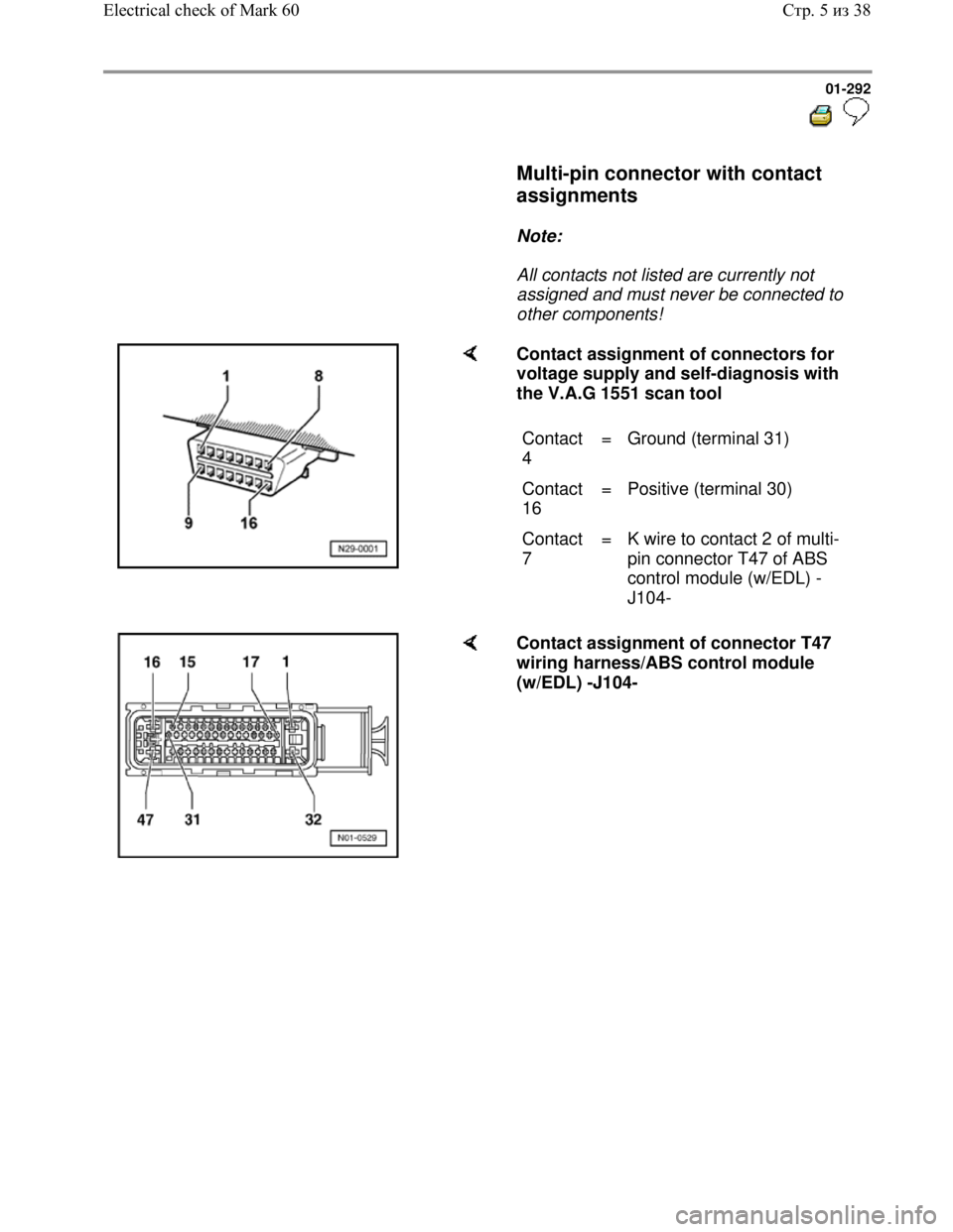
Multi-pin connector with contact
assignments
Note:
All contacts not listed are currently not
assigned and must never be connected to
other components!
Contact assignment of connectors for
voltage supply and self-diagnosis with
the V.A.G 1551 scan tool
Contact
4 = Ground (terminal 31)
Contact
16 = Positive (terminal 30)
Contact
7 = K wire to contact 2 of multi-
pin connector T47 of ABS
control module (w/EDL) -
J104-
Contact assignment of connector T47
wiring harness/ABS control module
(w/EDL) -J104-
Стр. 5из 38 Electrical check of Mark 60