check engine VOLKSWAGEN JETTA 1998 Workshop Manual
[x] Cancel search | Manufacturer: VOLKSWAGEN, Model Year: 1998, Model line: JETTA, Model: VOLKSWAGEN JETTA 1998Pages: 339, PDF Size: 2.35 MB
Page 72 of 339
Downloaded from www.Manualslib.com manuals search engine 01-69
Note:
For display group number 002 remember:
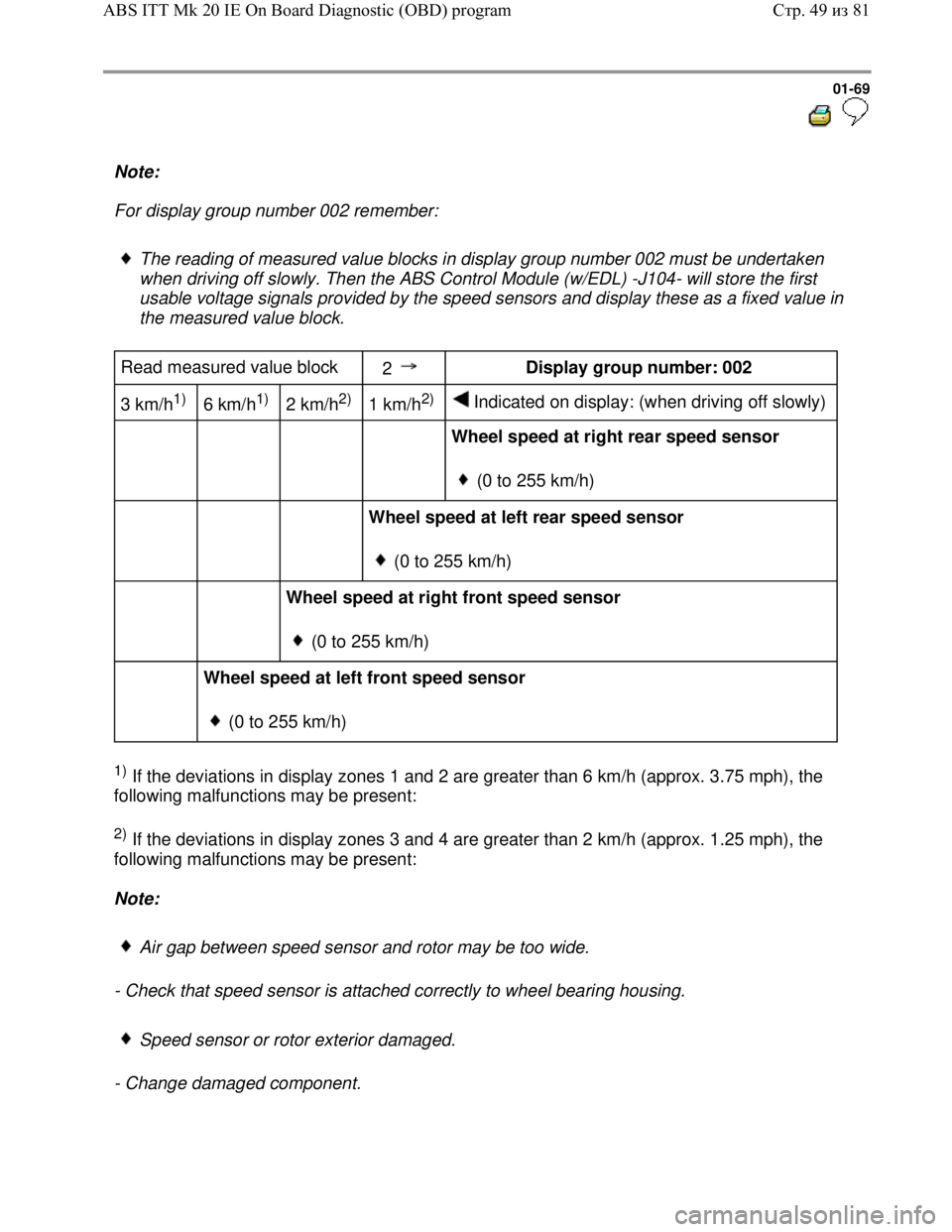
The reading of measured value blocks in display group number 002 must be undertaken
when driving off slowly. Then the ABS Control Module (w/EDL) -J104- will store the first
usable voltage signals provided by the speed sensors and display these as a fixed value in
the measured value block.
Read measured value block
2 Display group number: 002
3 km/h
1)
6 km/h1)
2 km/h2)
1 km/h2)
Indicated on display: (when driving off slowly)
Wheel speed at right rear speed sensor
(0 to 255 km/h)
Wheel speed at left rear speed sensor
(0 to 255 km/h)
Wheel speed at right front speed sensor
(0 to 255 km/h)
Wheel speed at left front speed sensor
(0 to 255 km/h)
1) If the deviations in display zones 1 and 2 are greater than 6 km/h (approx. 3.75 mph), the
following malfunctions may be present:
2) If the deviations in display zones 3 and 4 are greater than 2 km/h (approx. 1.25 mph), the
following malfunctions may be present:
Note:
Air gap between speed sensor and rotor may be too wide.
- Check that speed sensor is attached correctly to wheel bearing housing.
Speed sensor or rotor exterior damaged.
- Change damaged component.
Стр. 49из 81 ABS ITT Mk 20 IE On Board Diagnostic (OBD) program
Page 73 of 339
Downloaded from www.Manualslib.com manuals search engine 01-70
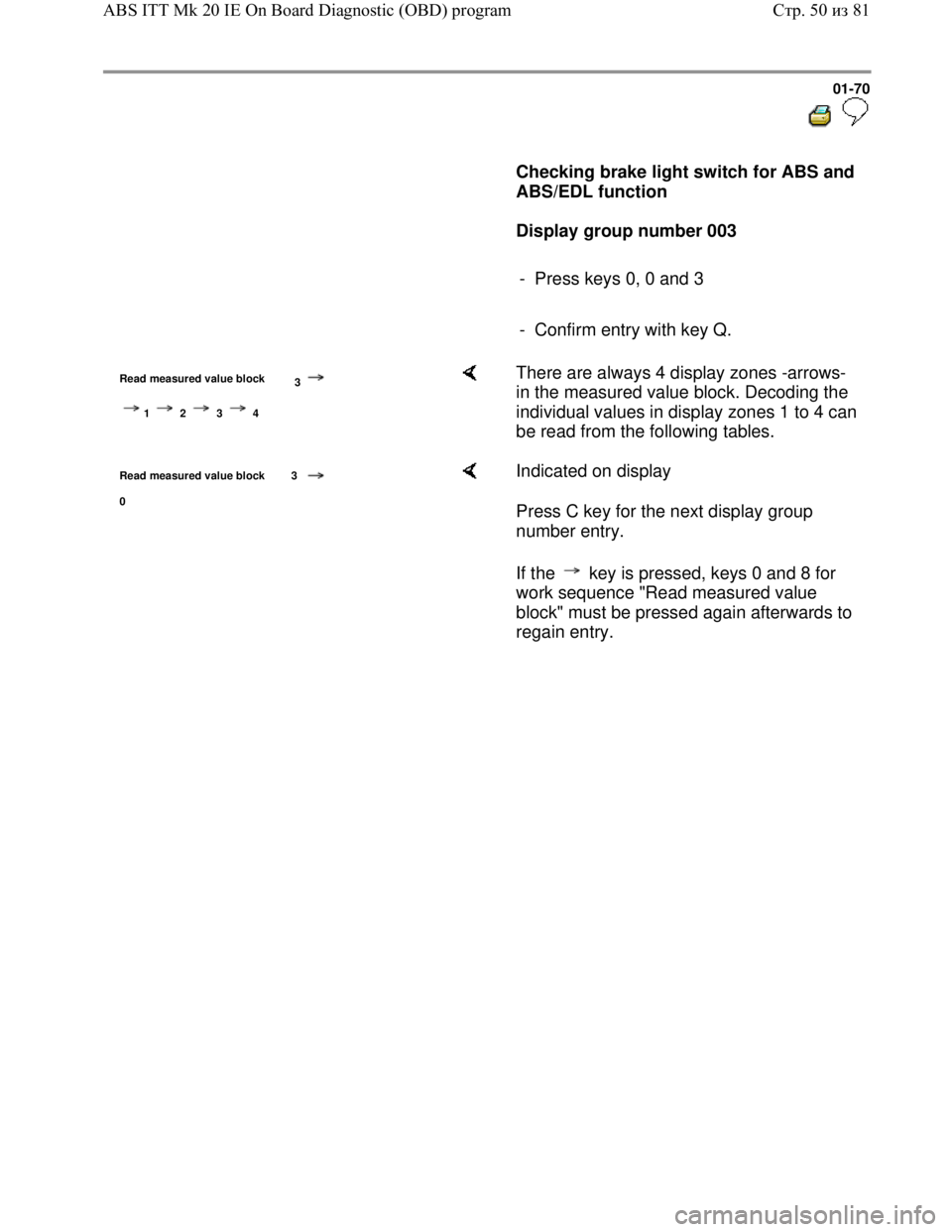
Checking brake light switch for ABS and
ABS/EDL function
Display group number 003
- Press keys 0, 0 and 3
- Confirm entry with key Q.
Read measured value block
3
1 2 3 4
There are always 4 display zones -arrows-
in the measured value block. Decoding the
individual values in display zones 1 to 4 can
be read from the following tables.
Read measured value block 3
0
Indicated on display
Press C key for the next display group
number entry.
If the key is pressed, keys 0 and 8 for
work sequence "Read measured value
block" must be pressed again afterwards to
regain entry.
Стр. 50из 81 ABS ITT Mk 20 IE On Board Diagnostic (OBD) program
Page 74 of 339
Downloaded from www.Manualslib.com manuals search engine 01-71
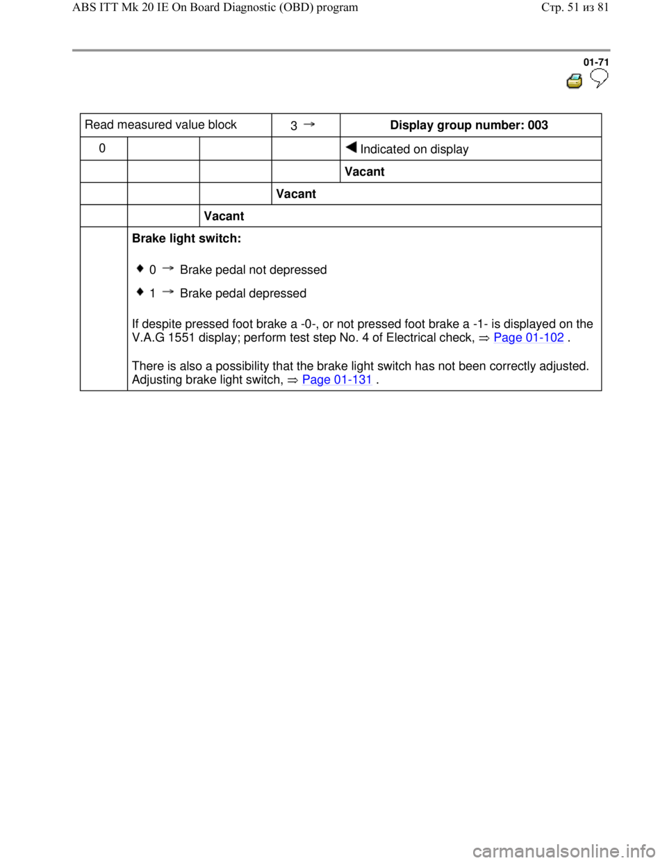
Read measured value block
3 Display group number: 003
0
Indicated on display
Vacant
Vacant
Vacant
Brake light switch:
If despite pressed foot brake a -0-, or not pressed foot brake a -1- is displayed on the
V.A.G 1551 display; perform test step No. 4 of Electrical check, Page 01
-102 .
There is also a possibility that the brake light switch has not been correctly adjusted.
Adjusting brake light switch, Page 01
-131 .
0 Brake pedal not depressed
1 Brake pedal depressed
Стр. 51из 81 ABS ITT Mk 20 IE On Board Diagnostic (OBD) program
Page 75 of 339
Downloaded from www.Manualslib.com manuals search engine 01-72
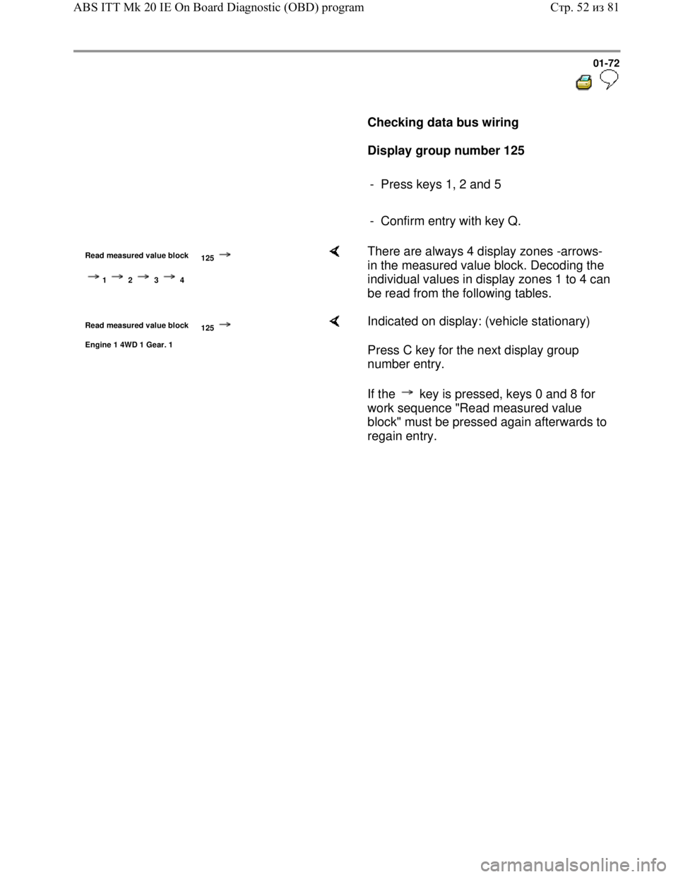
Checking data bus wiring
Display group number 125
- Press keys 1, 2 and 5
- Confirm entry with key Q.
Read measured value block
125
1 2 3 4
There are always 4 display zones -arrows-
in the measured value block. Decoding the
individual values in display zones 1 to 4 can
be read from the following tables.
Read measured value block
125
Engine 1 4WD 1 Gear. 1
Indicated on display: (vehicle stationary)
Press C key for the next display group
number entry.
If the key is pressed, keys 0 and 8 for
work sequence "Read measured value
block" must be pressed again afterwards to
regain entry.
Стр. 52из 81 ABS ITT Mk 20 IE On Board Diagnostic (OBD) program
Page 77 of 339
Downloaded from www.Manualslib.com manuals search engine 01-74
Output Diagnostic Test Mode (DTM)
Note:
All functions which could previously be
performed with V.A.G 1551 can also be
performed with the tester VAS 5051.
The pump motor and the correct functioning of
the hydraulic circuits (allocation of brake lines to
wheel cylinders and function of valves) can be
checked via the output DTM for interchange or
leaks.
The vehicle must be raised until all wheels are
free to turn. (2nd mechanic required to rotate
wheels)
The -C- key can be used to exit the test
sequence at any time.
After depressing the brake pedal several times
the vacuum in the brake booster will be
exhausted. Therefore more pressure must be
applied to the brake pedal in order to attain the
same fluid pressure in brake system, as that
attained with vacuum.
When vacuum in brake booster is exhausted
wheels may not lock; start engine and build-up
vacuum in brake booster.
Стр. 54из 81 ABS ITT Mk 20 IE On Board Diagnostic (OBD) program
Page 78 of 339
Downloaded from www.Manualslib.com manuals search engine 01-75
Example:
Indicated on V.A.G 1551 display during output
Diagnostic Test Mode (DTM):
(e.g. front left wheel, FL)
Output Diagnostic Test Mode -
IFL: VBAT OFL: 0V Wheel FL locked
IFL = Inlet valve Front Left
VBAT = Voltage Battery; Voltage at valve
OFL = Outlet valve Front Left
0V = 0 Volt; No voltage at valve
Locked/free = Wheel condition; must be
checked by 2nd mechanic if required
Output Diagnostic Test Mode -
EDL valves/Hyd-P: VBAT Wheel FL/FR
locked
Hydr-P = Hydraulic pump
Стр. 55из 81 ABS ITT Mk 20 IE On Board Diagnostic (OBD) program
Page 93 of 339
Downloaded from www.Manualslib.com manuals search engine 01-90
-
Press key.
The ABS warning light -K47- goes out.
Function is unknown or
cannot be carried out at the moment
Indicated on display
The Output Diagnostic Test Mode (DTM) is
completed
-
Press key.
Rapid data transfer HELP
Select function XX Indicated on display
Note:
There is a malfunction in the system if
the ABS warning light -K47- does not go
out.
Adhere exactly to test sequence: First
check Diagnostic Trouble Code (DTC)
memory, then erase.
- End output (Function 06) Page 01
-56 .
Стр. 70из 81 ABS ITT Mk 20 IE On Board Diagnostic (OBD) program
Page 105 of 339

Downloaded from www.Manualslib.com manuals search engine 01-102
ABS,
ABS/EDL and
ABS/EDL/ASR
ITT Mark 20
IE, electrical
check
Special tools and
equipment
V.A.G 1598/21
Adapter
V.A.G 1594 A
Adapter set
V.A.G 1526 A
Multimeter
V.A.G 1921 Pliers
Стр. 1из 31 ABS, ABS/EDL and ABS/EDL/ASR ITT Mark 20 IE, electrical check
Page 106 of 339
Downloaded from www.Manualslib.com manuals search engine 01-103
The test steps from Page 01-111 are valid
for:
For vehicles on which the On Board Diagnostic
(OBD) does not give any indication of the
source of the malfunction, work through the
complete electrical check.
For vehicles on which the OBD provides a
direct indication of the source of the
malfunction, only carry out the test steps
recommended in the Diagnostic Trouble Code
(DTC) table (directed entry).
An overview of all the test steps in the electrical
check can be found on Page 01
-109 .
Стр. 2из 31 ABS, ABS/EDL and ABS/EDL/ASR ITT Mark 20 IE, electrical check
Page 107 of 339
Downloaded from www.Manualslib.com manuals search engine 01-104
Test requirements
Switch ignition and electrical
consumers off before beginning the
check (headlights, lighting, fan ...).
Fuses S9, S13, S178 and S179 must
be OK (remove fuses from fuse holder
to check).
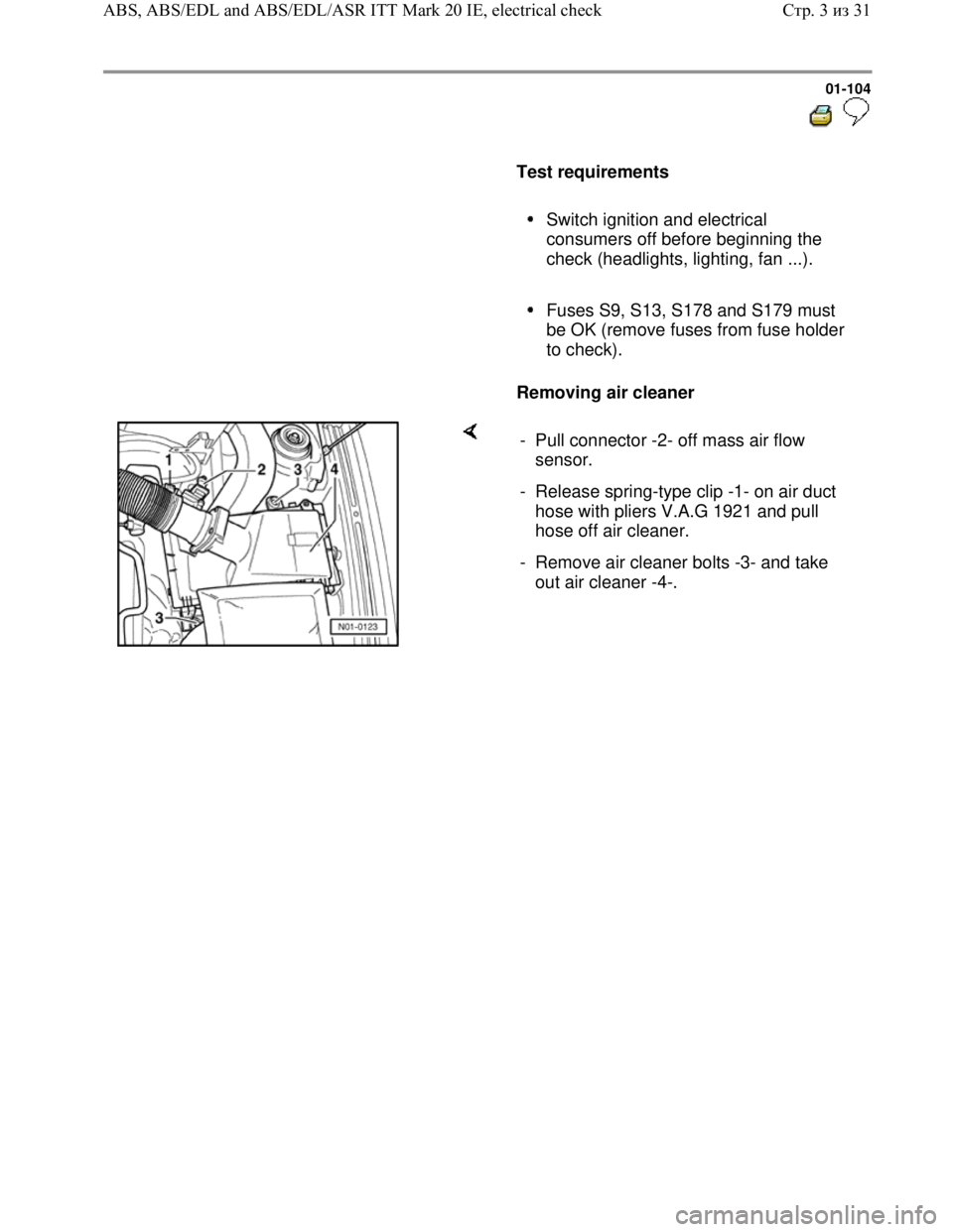
Removing air cleaner
- Pull connector -2- off mass air flow
sensor.
- Release spring-type clip -1- on air duct
hose with pliers V.A.G 1921 and pull
hose off air cleaner.
- Remove air cleaner bolts -3- and take
out air cleaner -4-.
Стр. 3из 31 ABS, ABS/EDL and ABS/EDL/ASR ITT Mark 20 IE, electrical check