display VOLKSWAGEN PASSAT 1995 B3, B4 / 3.G Service Workshop Manual
[x] Cancel search | Manufacturer: VOLKSWAGEN, Model Year: 1995, Model line: PASSAT, Model: VOLKSWAGEN PASSAT 1995 B3, B4 / 3.GPages: 369, PDF Size: 12.33 MB
Page 138 of 369
Downloaded from www.Manualslib.com manuals search engine 42-42
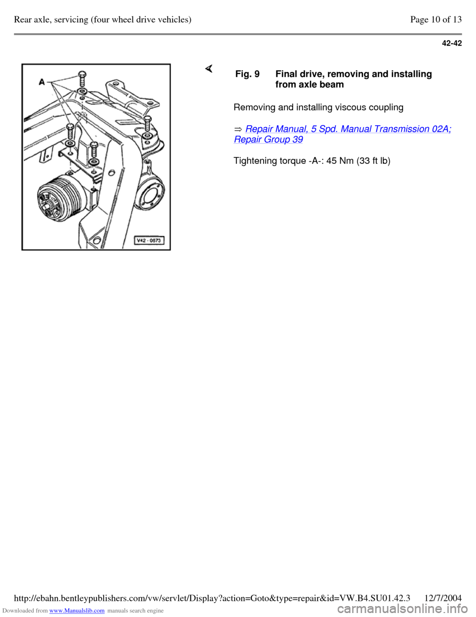
Removing and installing viscous coupling
Repair Manual, 5 Spd. Manual Transmission 02A; Repair Group 39
Tightening torque -A-: 45 Nm (33 ft lb) Fig. 9 Final drive, removing and installing
from axle beam Page 10 of 13Rear axle, servicing (four wheel drive vehicles)12/7/2004http://ebahn.bentleypublishers.com/vw/servlet/Display?action=Goto&type=repair&id=VW.B4.SU01.42.3
Page 139 of 369
Downloaded from www.Manualslib.com manuals search engine 42-43
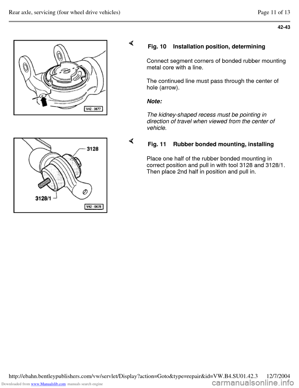
Connect segment corners of bonded rubber mounting
metal core with a line.
The continued line must pass through the center of
hole (arrow).
Note:
The kidney-shaped recess must be pointing in
direction of travel when viewed from the center of
vehicle. Fig. 10 Installation position, determining Place one half of the rubber bonded mounting in
correct position and pull in with tool 3128 and 3128/1.
Then place 2nd half in position and pull in. Fig. 11 Rubber bonded mounting, installing Page 11 of 13Rear axle, servicing (four wheel drive vehicles)12/7/2004http://ebahn.bentleypublishers.com/vw/servlet/Display?action=Goto&type=repair&id=VW.B4.SU01.42.3
Page 140 of 369
Downloaded from www.Manualslib.com manuals search engine 42-44
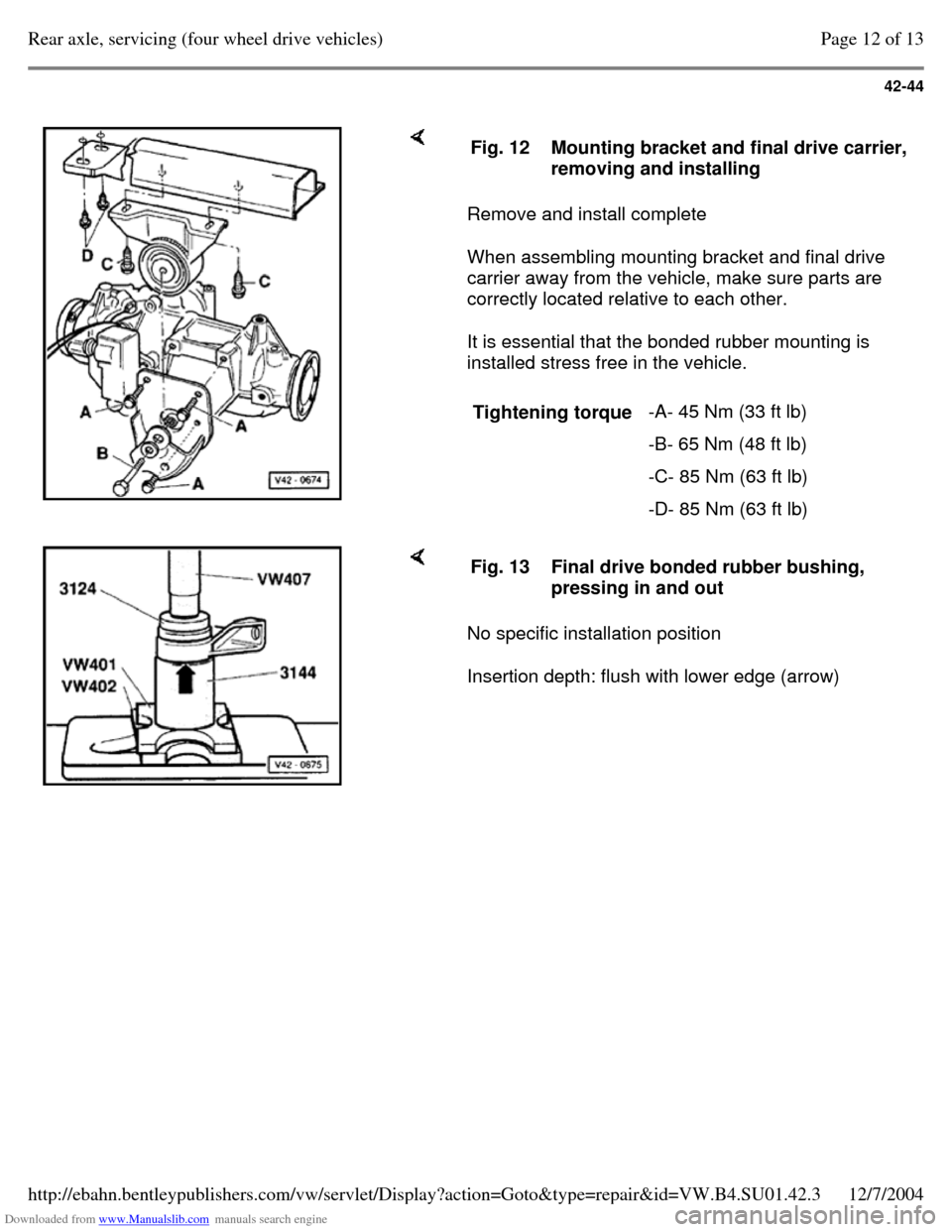
Remove and install complete
When assembling mounting bracket and final drive
carrier away from the vehicle, make sure parts are
correctly located relative to each other.
It is essential that the bonded rubber mounting is
installed stress free in the vehicle. Fig. 12 Mounting bracket and final drive carrier, removing and installing
Tightening torque -A- 45 Nm (33 ft lb)
-B- 65 Nm (48 ft lb)
-C- 85 Nm (63 ft lb)
-D- 85 Nm (63 ft lb) No specific installation position
Insertion depth: flush with lower edge (arrow) Fig. 13 Final drive bonded rubber bushing,
pressing in and out Page 12 of 13Rear axle, servicing (four wheel drive vehicles)12/7/2004http://ebahn.bentleypublishers.com/vw/servlet/Display?action=Goto&type=repair&id=VW.B4.SU01.42.3
Page 141 of 369
Downloaded from www.Manualslib.com manuals search engine 42-45
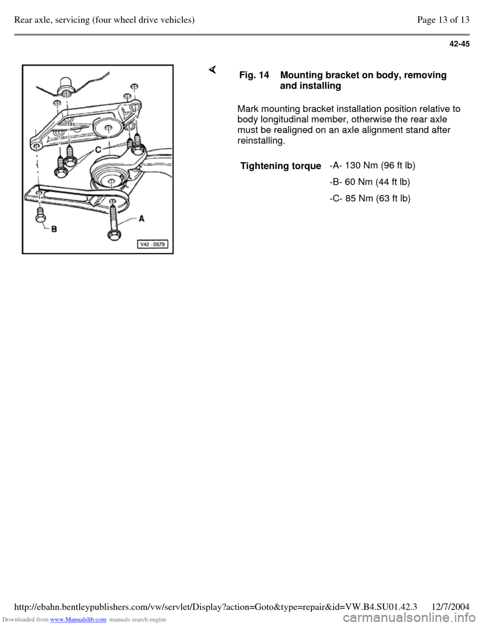
Mark mounting bracket installation position relative to
body longitudinal member, otherwise the rear axle
must be realigned on an axle alignment stand after
reinstalling. Fig. 14 Mounting bracket on body, removing
and installing
Tightening torque -A- 130 Nm (96 ft lb)
-B- 60 Nm (44 ft lb)
-C- 85 Nm (63 ft lb) Page 13 of 13Rear axle, servicing (four wheel drive vehicles)12/7/2004http://ebahn.bentleypublishers.com/vw/servlet/Display?action=Goto&type=repair&id=VW.B4.SU01.42.3
Page 142 of 369
Downloaded from www.Manualslib.com manuals search engine 42-46
Rear drive shafts, servicing
Removing and installing drive shafts Page 42-37
Note:
Grease quantity:
- - outer constant velocity joint 80 g G-6.3
- - inner constant velocity joint 80 9 G-6.3 Greasing outer joint: press half of the grease
into the joint, and the other half evenly into the
boot.
Greasing inner joint: press half of the grease
into the inner joint from both sides, the other
half evenly into the boot.
When replacing the boot, regrease joint if
required. Page 1 of 7Rear drive shafts, servicing12/7/2004http://ebahn.bentleypublishers.com/vw/servlet/Display?action=Goto&type=repair&id=VW.B4.SU01.42.4
Page 143 of 369
Downloaded from www.Manualslib.com manuals search engine 42-47
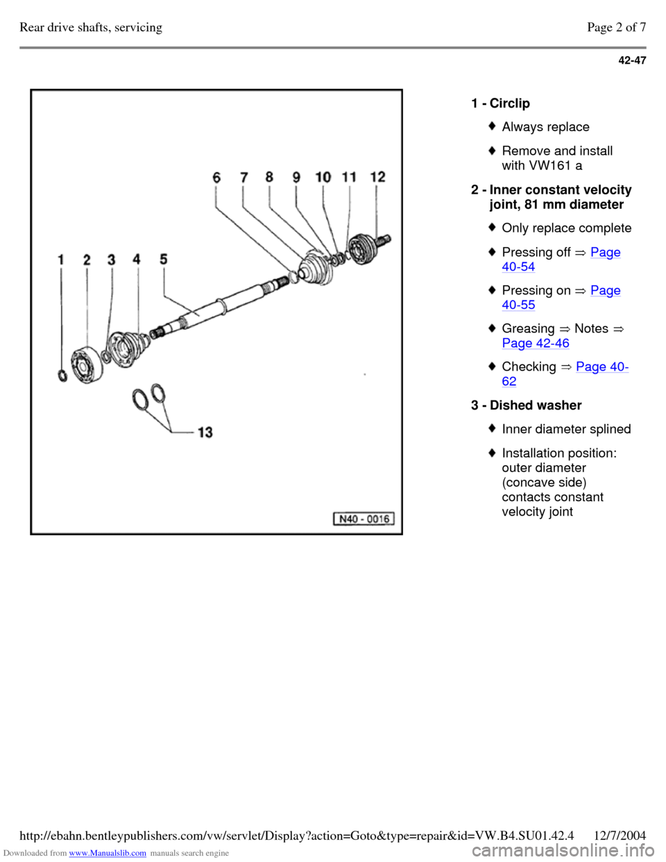
1 - Circlip Always replace Remove and install
with VW161 a
2 - Inner constant velocity
joint, 81 mm diameter Only replace complete Pressing off Page 40-54 Pressing on Page 40-55 Greasing Notes
Page 42-46 Checking Page 40-62 3 - Dished washer Inner diameter splined Installation position:
outer diameter
(concave side)
contacts constant
velocity joint Page 2 of 7Rear drive shafts, servicing12/7/2004http://ebahn.bentleypublishers.com/vw/servlet/Display?action=Goto&type=repair&id=VW.B4.SU01.42.4
Page 144 of 369
Downloaded from www.Manualslib.com manuals search engine 42-48
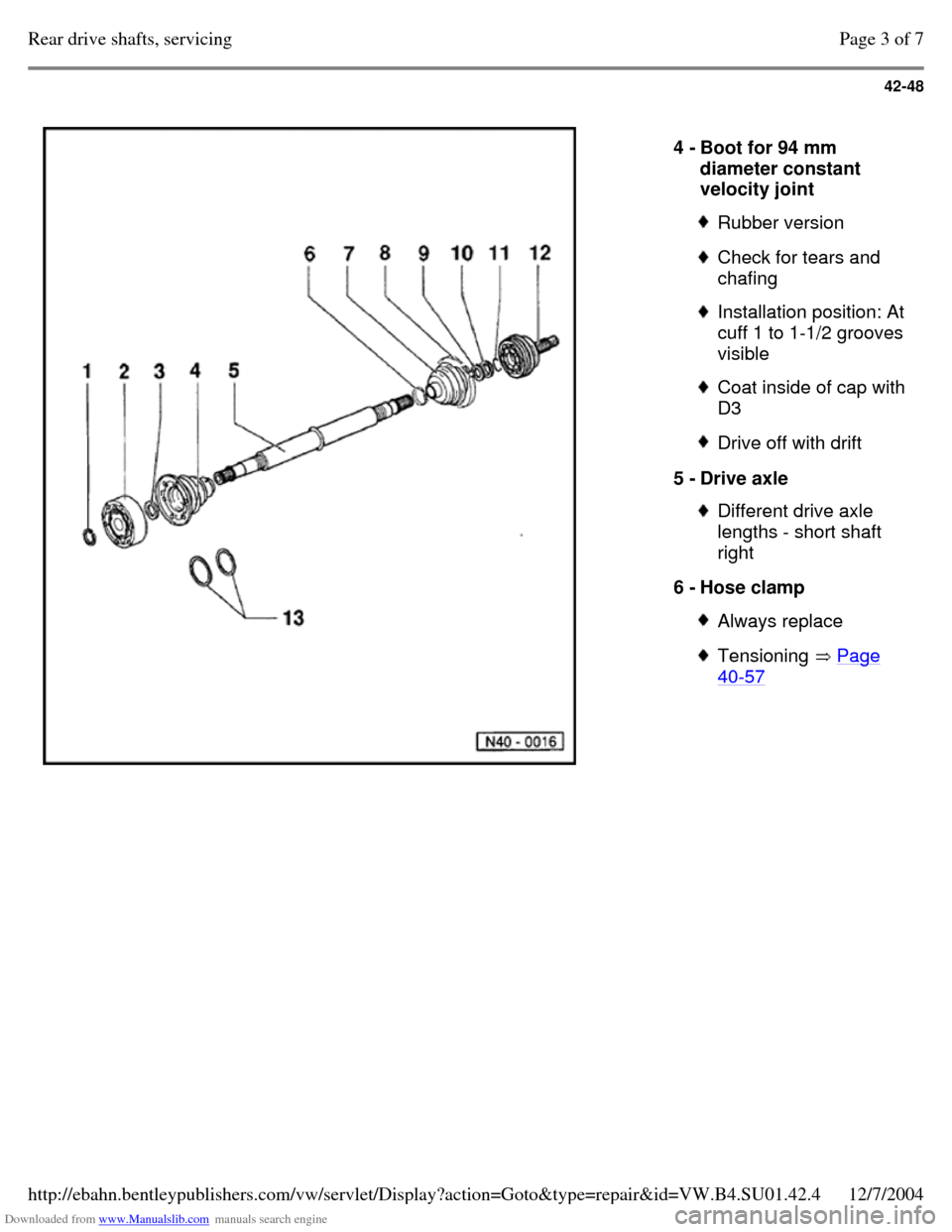
4 - Boot for 94 mm
diameter constant
velocity joint Rubber version Check for tears and
chafing Installation position: At
cuff 1 to 1-1/2 grooves
visible Coat inside of cap with D3 Drive off with drift 5 - Drive axle Different drive axle
lengths - short shaft
right
6 - Hose clamp Always replace Tensioning Page 40-57 Page 3 of 7Rear drive shafts, servicing12/7/2004http://ebahn.bentleypublishers.com/vw/servlet/Display?action=Goto&type=repair&id=VW.B4.SU01.42.4
Page 145 of 369
Downloaded from www.Manualslib.com manuals search engine 42-49
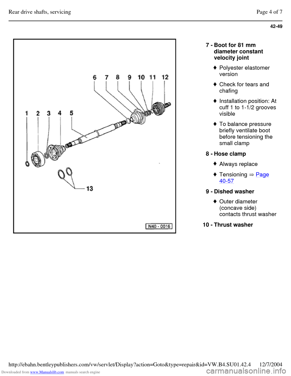
7 - Boot for 81 mm
diameter constant
velocity joint Polyester elastomer
version Check for tears and
chafing Installation position: At
cuff 1 to 1-1/2 grooves
visible To balance pressure
briefly ventilate boot
before tensioning the
small clamp
8 - Hose clamp Always replace Tensioning Page 40-57 9 - Dished washer Outer diameter
(concave side)
contacts thrust washer
10 - Thrust washer Page 4 of 7Rear drive shafts, servicing12/7/2004http://ebahn.bentleypublishers.com/vw/servlet/Display?action=Goto&type=repair&id=VW.B4.SU01.42.4
Page 146 of 369
Downloaded from www.Manualslib.com manuals search engine 42-50
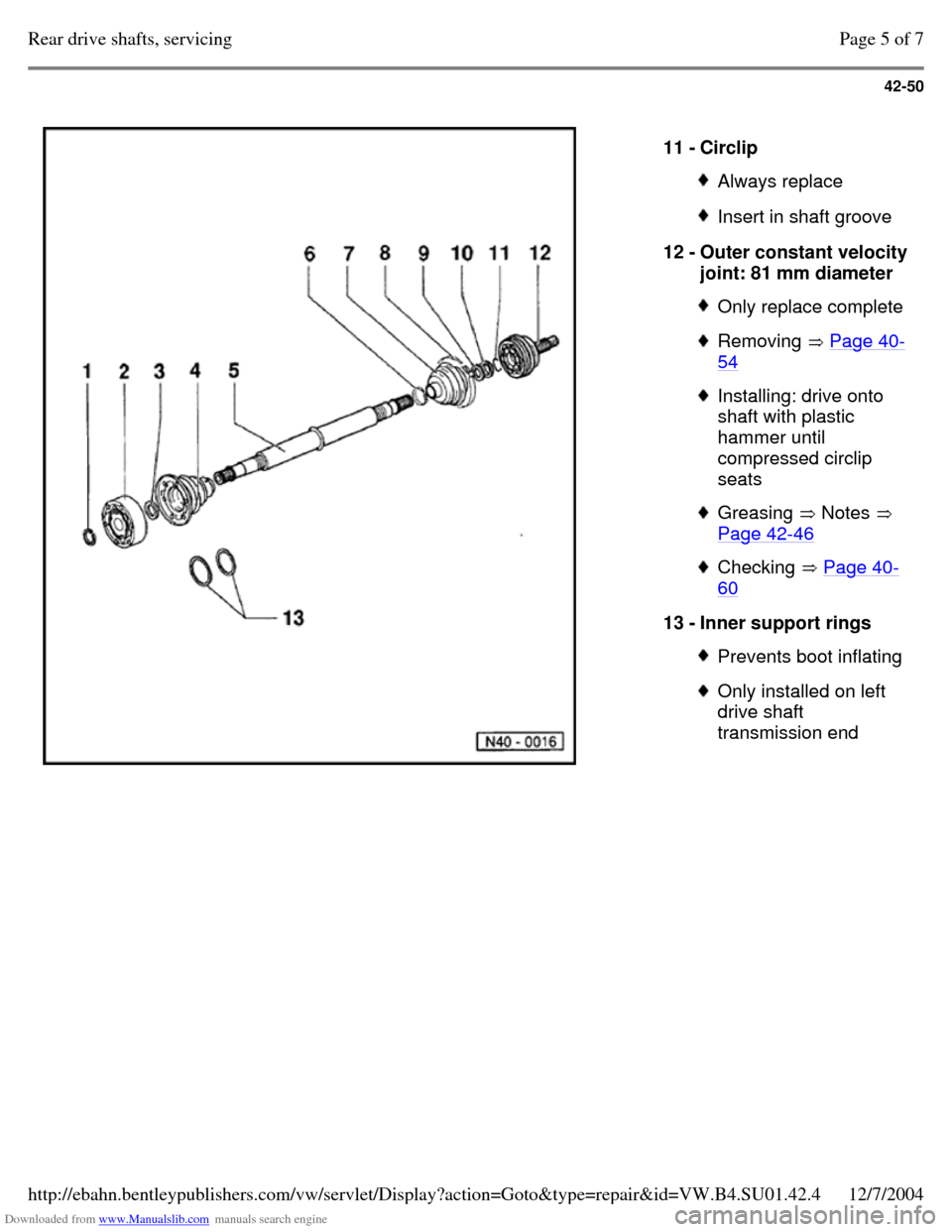
11 - Circlip Always replace Insert in shaft groove 12 - Outer constant velocity joint: 81 mm diameter Only replace complete Removing Page 40-54 Installing: drive onto
shaft with plastic
hammer until
compressed circlip
seats Greasing Notes
Page 42-46 Checking Page 40-60 13 - Inner support rings Prevents boot inflating Only installed on left
drive shaft
transmission end Page 5 of 7Rear drive shafts, servicing12/7/2004http://ebahn.bentleypublishers.com/vw/servlet/Display?action=Goto&type=repair&id=VW.B4.SU01.42.4
Page 147 of 369
Downloaded from www.Manualslib.com manuals search engine 42-51
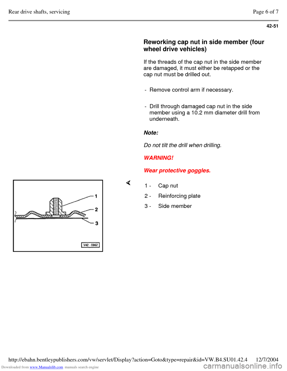
Reworking cap nut in side member (four
wheel drive vehicles)
If the threads of the cap nut in the side member
are damaged, it must either be retapped or the
cap nut must be drilled out.
- Remove control arm if necessary.
- Drill through damaged cap nut in the side
member using a 10.2 mm diameter drill from
underneath.
Note:
Do not tilt the drill when drilling.
WARNING!
Wear protective goggles. 1 - Cap nut 2 - Reinforcing plate 3 - Side member Page 6 of 7Rear drive shafts, servicing12/7/2004http://ebahn.bentleypublishers.com/vw/servlet/Display?action=Goto&type=repair&id=VW.B4.SU01.42.4