display VOLKSWAGEN PASSAT 1995 B3, B4 / 3.G Service Owners Manual
[x] Cancel search | Manufacturer: VOLKSWAGEN, Model Year: 1995, Model line: PASSAT, Model: VOLKSWAGEN PASSAT 1995 B3, B4 / 3.GPages: 369, PDF Size: 12.33 MB
Page 97 of 369
Downloaded from www.Manualslib.com manuals search engine 42-1
Rear Wheel
Suspension, Shafts
and Axle
Rear axle, servicing
(vehicles with front wheel
drive)
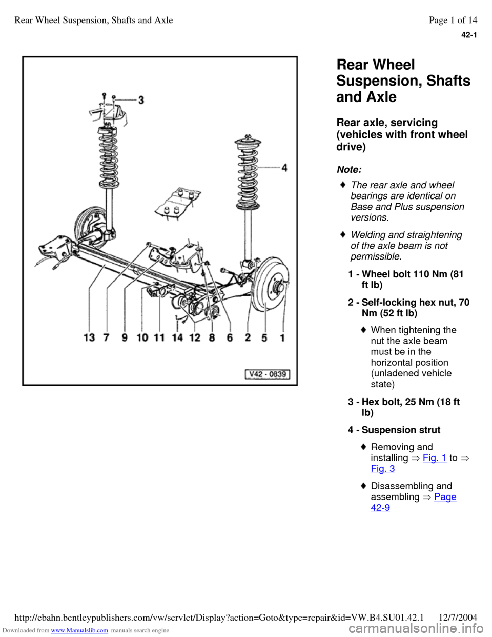
Note: The rear axle and wheel
bearings are identical on
Base and Plus suspension
versions. Welding and straightening
of the axle beam is not
permissible.
1 - Wheel bolt 110 Nm (81
ft lb)
2 - Self-locking hex nut, 70 Nm (52 ft lb) When tightening the
nut the axle beam
must be in the
horizontal position
(unladened vehicle
state)
3 - Hex bolt, 25 Nm (18 ft
lb)
4 - Suspension strut Removing and
installing Fig. 1 to Fig. 3 Disassembling and
assembling Page 42-9 Page 1 of 14Rear Wheel Suspension, Shafts and Axle12/7/2004http://ebahn.bentleypublishers.com/vw/servlet/Display?action=Goto&type=repair&id=VW.B4.SU01.42.1
Page 98 of 369
Downloaded from www.Manualslib.com manuals search engine 42-2
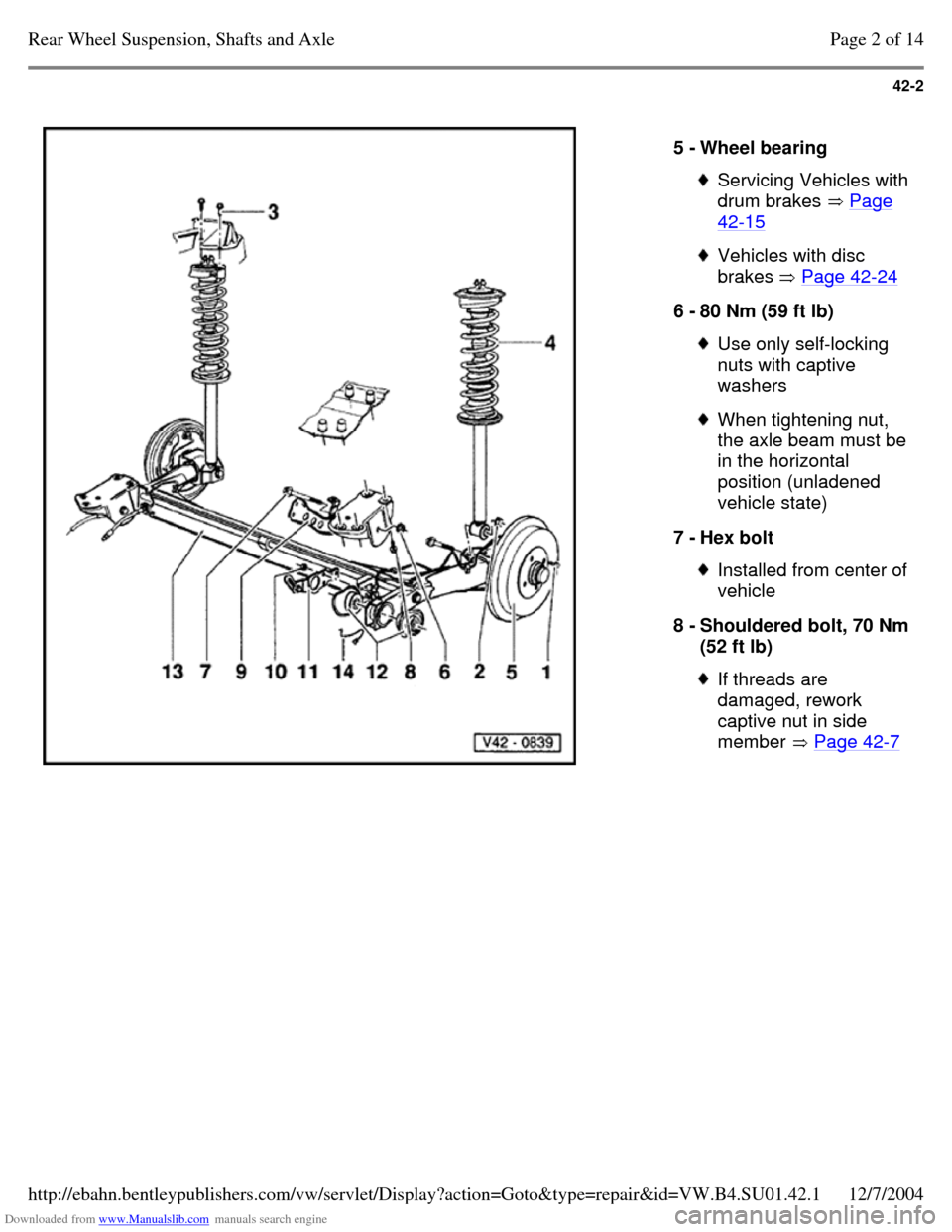
5 - Wheel bearing Servicing Vehicles with drum brakes Page 42-15 Vehicles with disc
brakes Page 42-24 6 - 80 Nm (59 ft lb) Use only self-locking
nuts with captive
washers When tightening nut, the axle beam must be in the horizontal
position (unladened
vehicle state)
7 - Hex bolt Installed from center of vehicle
8 - Shouldered bolt, 70 Nm (52 ft lb) If threads are
damaged, rework
captive nut in side
member Page 42-7 Page 2 of 14Rear Wheel Suspension, Shafts and Axle12/7/2004http://ebahn.bentleypublishers.com/vw/servlet/Display?action=Goto&type=repair&id=VW.B4.SU01.42.1
Page 99 of 369
Downloaded from www.Manualslib.com manuals search engine 42-3
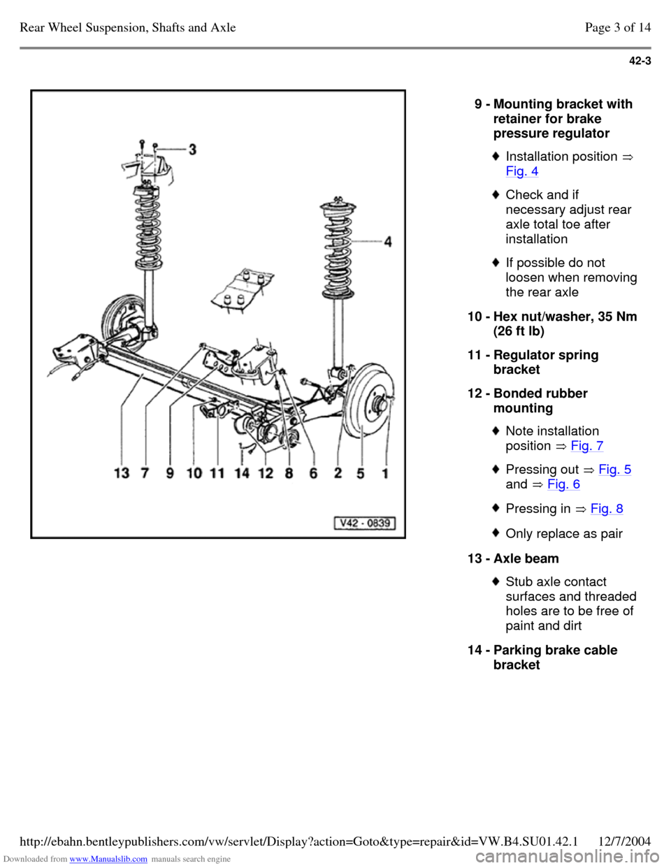
9 - Mounting bracket with
retainer for brake
pressure regulator Installation position
Fig. 4 Check and if
necessary adjust rear
axle total toe after
installation If possible do not
loosen when removing
the rear axle
10 - Hex nut/washer, 35 Nm
(26 ft lb)
11 - Regulator spring
bracket
12 - Bonded rubber
mounting Note installation
position Fig. 7 Pressing out Fig. 5
and Fig. 6 Pressing in Fig. 8 Only replace as pair 13 - Axle beam Stub axle contact
surfaces and threaded
holes are to be free of
paint and dirt
14 - Parking brake cable
bracket Page 3 of 14Rear Wheel Suspension, Shafts and Axle12/7/2004http://ebahn.bentleypublishers.com/vw/servlet/Display?action=Goto&type=repair&id=VW.B4.SU01.42.1
Page 100 of 369
Downloaded from www.Manualslib.com manuals search engine 42-4
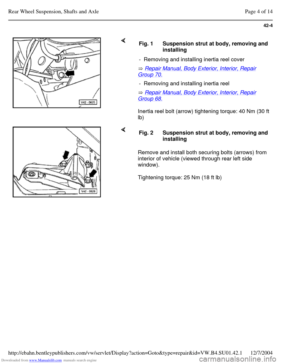
Repair Manual, Body Exterior, Interior, Repair Group 70.
Repair Manual, Body Exterior, Interior, Repair Group 68.
Inertia reel bolt (arrow) tightening torque: 40 Nm (30 ft
lb) Fig. 1 Suspension strut at body, removing and installing
- Removing and installing inertia reel cover - Removing and installing inertia reel Remove and install both securing bolts (arrows) from
interior of vehicle (viewed through rear left side
window).
Tightening torque: 25 Nm (18 ft lb) Fig. 2 Suspension strut at body, removing and installing Page 4 of 14Rear Wheel Suspension, Shafts and Axle12/7/2004http://ebahn.bentleypublishers.com/vw/servlet/Display?action=Goto&type=repair&id=VW.B4.SU01.42.1
Page 101 of 369
Downloaded from www.Manualslib.com manuals search engine 42-5
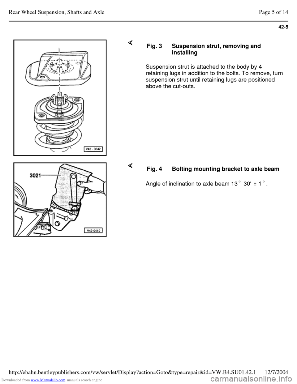
Suspension strut is attached to the body by 4
retaining lugs in addition to the bolts. To remove, turn
suspension strut until retaining lugs are positioned
above the cut-outs. Fig. 3 Suspension strut, removing and
installing Angle of inclination to axle beam 13 30' 1. Fig. 4 Bolting mounting bracket to axle beam Page 5 of 14Rear Wheel Suspension, Shafts and Axle12/7/2004http://ebahn.bentleypublishers.com/vw/servlet/Display?action=Goto&type=repair&id=VW.B4.SU01.42.1
Page 102 of 369
Downloaded from www.Manualslib.com manuals search engine 42-6
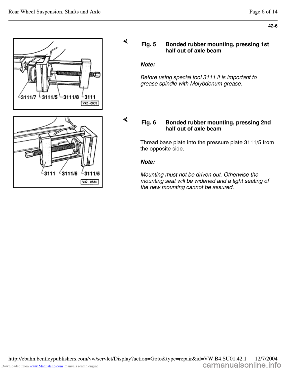
Note:
Before using special tool 3111 it is important to
grease spindle with Molybdenum grease. Fig. 5 Bonded rubber mounting, pressing 1st
half out of axle beam Thread base plate into the pressure plate 3111/5 from
the opposite side.
Note:
Mounting must not be driven out. Otherwise the
mounting seat will be widened and a tight seating of
the new mounting cannot be assured. Fig. 6 Bonded rubber mounting, pressing 2nd
half out of axle beam Page 6 of 14Rear Wheel Suspension, Shafts and Axle12/7/2004http://ebahn.bentleypublishers.com/vw/servlet/Display?action=Goto&type=repair&id=VW.B4.SU01.42.1
Page 103 of 369
Downloaded from www.Manualslib.com manuals search engine 42-7
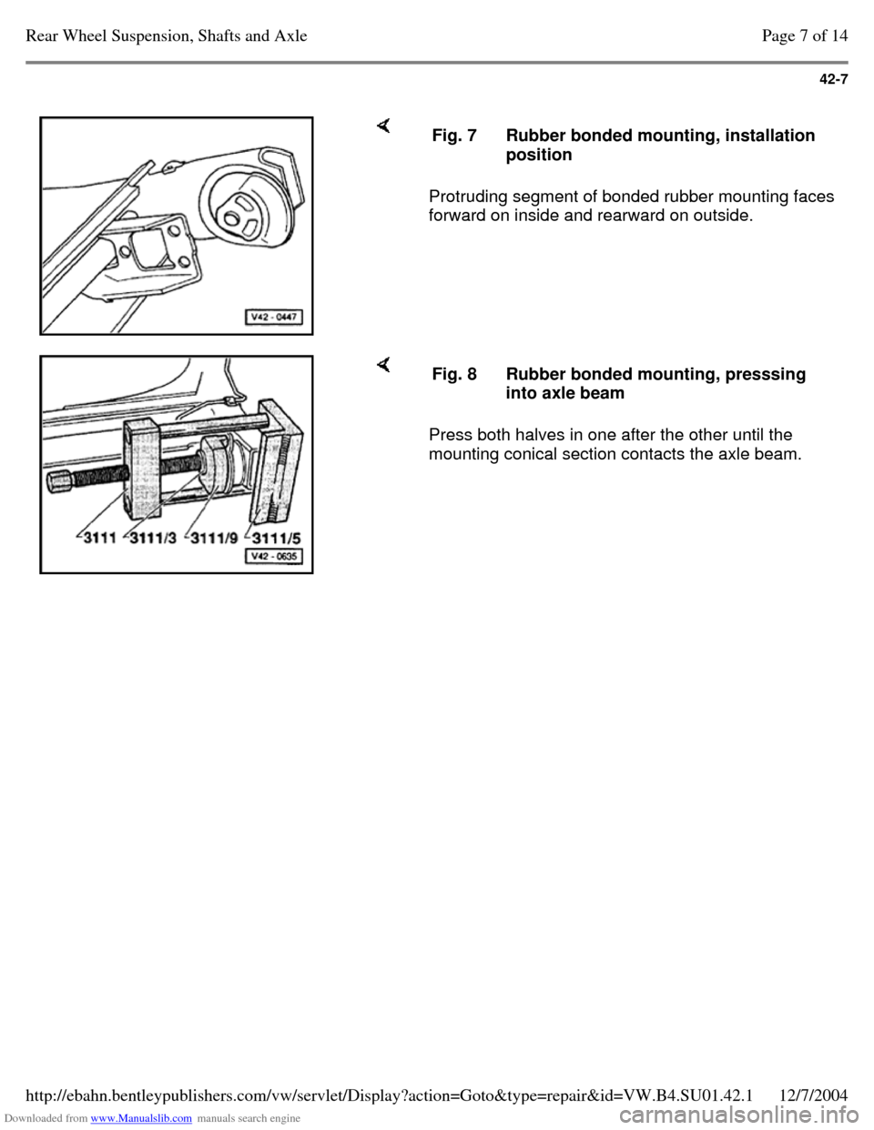
Protruding segment of bonded rubber mounting faces
forward on inside and rearward on outside. Fig. 7 Rubber bonded mounting, installation
position Press both halves in one after the other until the
mounting conical section contacts the axle beam. Fig. 8 Rubber bonded mounting, presssing
into axle beam Page 7 of 14Rear Wheel Suspension, Shafts and Axle12/7/2004http://ebahn.bentleypublishers.com/vw/servlet/Display?action=Goto&type=repair&id=VW.B4.SU01.42.1
Page 104 of 369
Downloaded from www.Manualslib.com manuals search engine 42-8
Reworking cap nut in side member
(front wheel drive vehicles)
If the threads of the cap nut in the side member
are damaged, it must either be retapped or the
cap nut must be drilled out. When drilling out
proceed as follows:
- Remove rear axle.
- Drill through damaged cap nut in the side
member using a 10.2 mm diameter drill from
underneath.
Note:
Do not tilt the drill when drilling.
WARNING!
Wear protective goggles.
- Cut new thread in the cap nut, M 12 x 1.5.
- Use new bolts, Part No. N 010.127.4 (M 12 x 1.5 x 30), and washer, Part No. N 011.531.7, to
secure the rear axle.
Tightening torque: 70 Nm (52 ft lb)
Note:
The procedure described here must only be
performed on one cap nut on each side of the
vehicle. Page 8 of 14Rear Wheel Suspension, Shafts and Axle12/7/2004http://ebahn.bentleypublishers.com/vw/servlet/Display?action=Goto&type=repair&id=VW.B4.SU01.42.1
Page 105 of 369
Downloaded from www.Manualslib.com manuals search engine 42-9
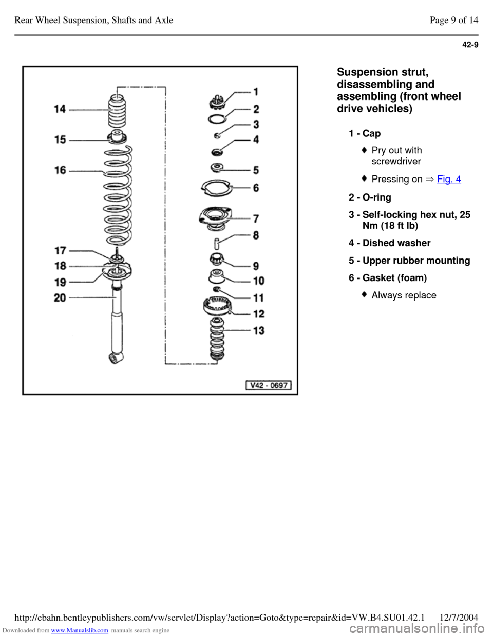
Suspension strut,
disassembling and
assembling (front wheel
drive vehicles)
1 - Cap Pry out with
screwdriver Pressing on Fig. 4 2 - O-ring
3 - Self-locking hex nut, 25 Nm (18 ft lb)
4 - Dished washer
5 - Upper rubber mounting 6 - Gasket (foam) Always replace Page 9 of 14Rear Wheel Suspension, Shafts and Axle12/7/2004http://ebahn.bentleypublishers.com/vw/servlet/Display?action=Goto&type=repair&id=VW.B4.SU01.42.1
Page 106 of 369
Downloaded from www.Manualslib.com manuals search engine 42-10
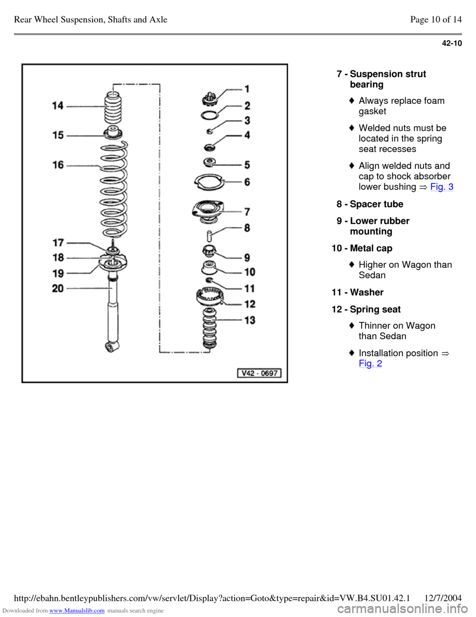
7 - Suspension strut
bearing Always replace foam
gasket Welded nuts must be
located in the spring
seat recesses Align welded nuts and
cap to shock absorber
lower bushing Fig. 3 8 - Spacer tube
9 - Lower rubber
mounting
10 - Metal cap Higher on Wagon than
Sedan
11 - Washer
12 - Spring seat Thinner on Wagon
than Sedan Installation position
Fig. 2 Page 10 of 14Rear Wheel Suspension, Shafts and Axle12/7/2004http://ebahn.bentleypublishers.com/vw/servlet/Display?action=Goto&type=repair&id=VW.B4.SU01.42.1