lock VOLKSWAGEN PASSAT 1995 B3, B4 / 3.G Service Repair Manual
[x] Cancel search | Manufacturer: VOLKSWAGEN, Model Year: 1995, Model line: PASSAT, Model: VOLKSWAGEN PASSAT 1995 B3, B4 / 3.GPages: 369, PDF Size: 12.33 MB
Page 256 of 369
Downloaded from www.Manualslib.com manuals search engine 47-15
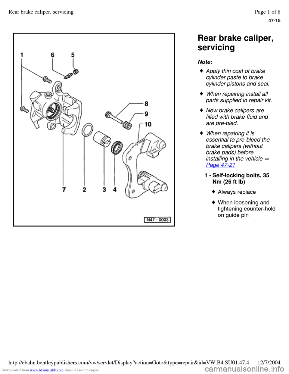
Rear brake caliper,
servicing
Note: Apply thin coat of brake
cylinder paste to brake
cylinder pistons and seal. When repairing install all
parts supplied in repair kit. New brake calipers are
filled with brake fluid and
are pre-bled. When repairing it is
essential to pre-bleed the
brake calipers (without
brake pads) before
installing in the vehicle
Page 47-21 1 - Self-locking bolts, 35
Nm (26 ft lb) Always replace When loosening and
tightening counter-hold on guide pin Page 1 of 8Rear brake caliper, servicing12/7/2004http://ebahn.bentleypublishers.com/vw/servlet/Display?action=Goto&type=repair&id=VW.B4.SU01.47.4
Page 260 of 369
Downloaded from www.Manualslib.com manuals search engine 47-19
Rear brake caliper piston, removing and
installing
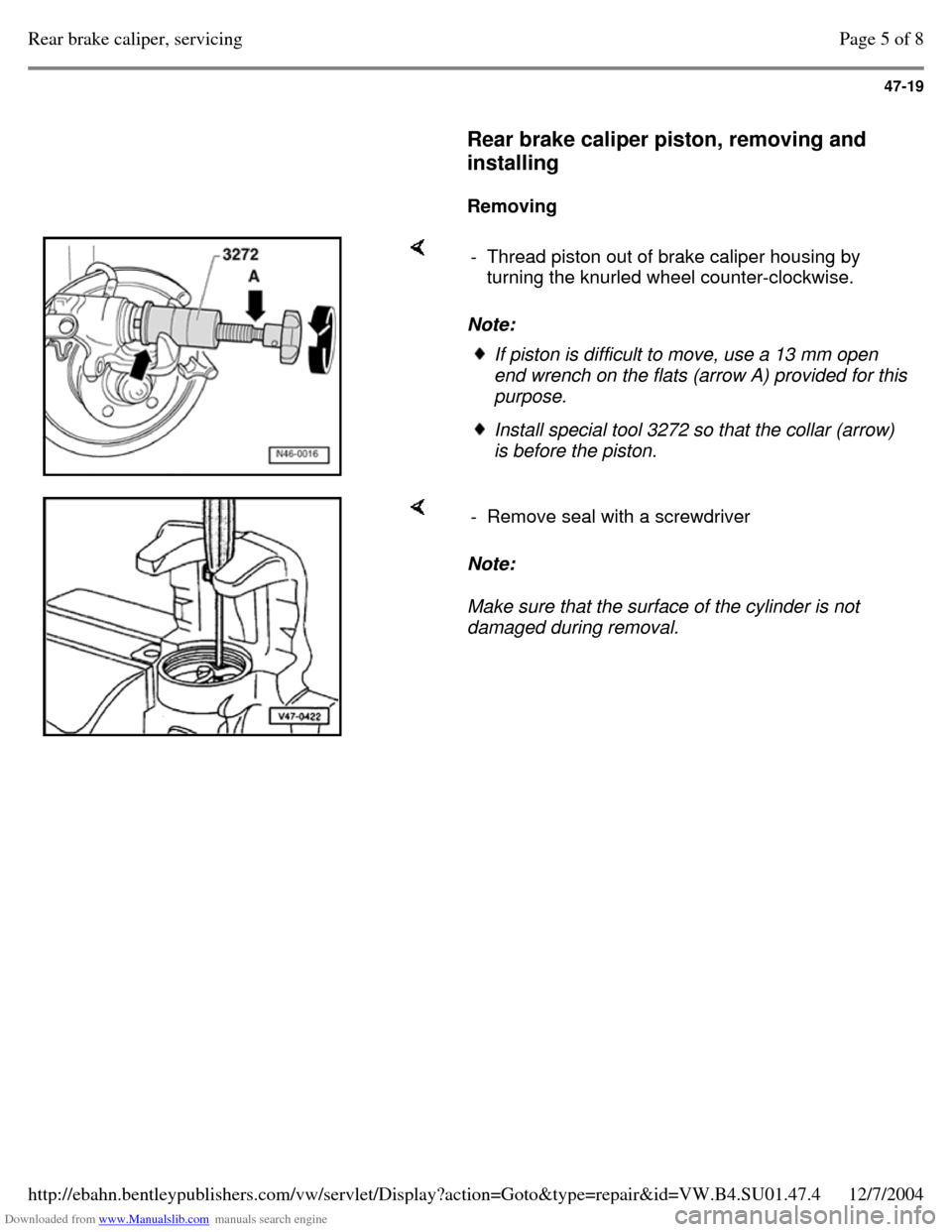
Removing Note: - Thread piston out of brake caliper housing by
turning the knurled wheel counter-clockwise. If piston is difficult to move, use a 13 mm open
end wrench on the flats (arrow A) provided for this
purpose. Install special tool 3272 so that the collar (arrow)
is before the piston. Note:
Make sure that the surface of the cylinder is not
damaged during removal. - Remove seal with a screwdriver Page 5 of 8Rear brake caliper, servicing12/7/2004http://ebahn.bentleypublishers.com/vw/servlet/Display?action=Goto&type=repair&id=VW.B4.SU01.47.4
Page 262 of 369
Downloaded from www.Manualslib.com manuals search engine 47-21
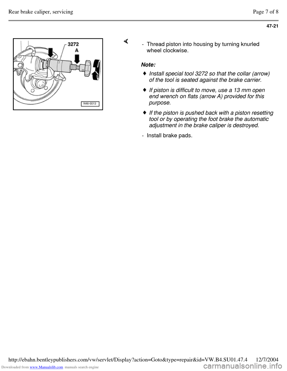
Note: - Thread piston into housing by turning knurled
wheel clockwise. Install special tool 3272 so that the collar (arrow)
of the tool is seated against the brake carrier. If piston is difficult to move, use a 13 mm open
end wrench on flats (arrow A) provided for this
purpose. If the piston is pushed back with a piston resetting
tool or by operating the foot brake the automatic
adjustment in the brake caliper is destroyed.
- Install brake pads. Page 7 of 8Rear brake caliper, servicing12/7/2004http://ebahn.bentleypublishers.com/vw/servlet/Display?action=Goto&type=repair&id=VW.B4.SU01.47.4
Page 271 of 369
Downloaded from www.Manualslib.com manuals search engine 48-1
Steering
Assembly overview: steering column,
column tube, steering wheel and airbag
steering wheel
Airbag system functional check and
interrogating Diagnostic Trouble Code (DTC)
Memory.
Repair Manual, Body Exterior, Interior, Repair Group 68; General body repairs
Safety precautions when working on airbag
Repair Manual, Body Exterior, Interior, Repair Group 68, General body repairs
Note:
All parts marked with a "1)
" can be pre-
assembled outside of the vehicle
Pre-assembling steering column Page 48-6 Always replace self-locking nuts and bolts. Welding and straightening work on steering
components is not permitted. Page 1 of 99Steering12/7/2004http://ebahn.bentleypublishers.com/vw/servlet/Display?action=Goto&type=repair&id=VW.B4.SU01.48.1
Page 273 of 369
Downloaded from www.Manualslib.com manuals search engine 48-3
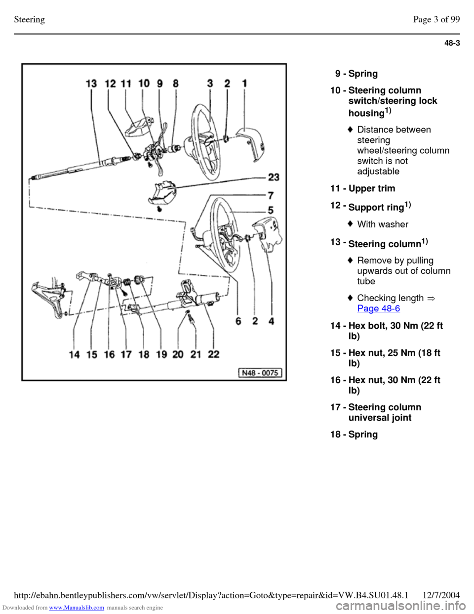
9 - Spring
10 - Steering column
switch/steering lock
housing1)
Distance between
steering
wheel/steering column
switch is not
adjustable
11 - Upper trim
12 - Support ring1)
With washer 13 - Steering column1)
Remove by pulling upwards out of column tube Checking length
Page 48-6 14 - Hex bolt, 30 Nm (22 ft
lb)
15 - Hex nut, 25 Nm (18 ft
lb)
16 - Hex nut, 30 Nm (22 ft
lb)
17 - Steering column
universal joint
18 - Spring Page 3 of 99Steering12/7/2004http://ebahn.bentleypublishers.com/vw/servlet/Display?action=Goto&type=repair&id=VW.B4.SU01.48.1
Page 278 of 369
Downloaded from www.Manualslib.com manuals search engine 48-8
Airbag steering wheel, removing and
installing
Removing
- Remove airbag unit. Page 48-7
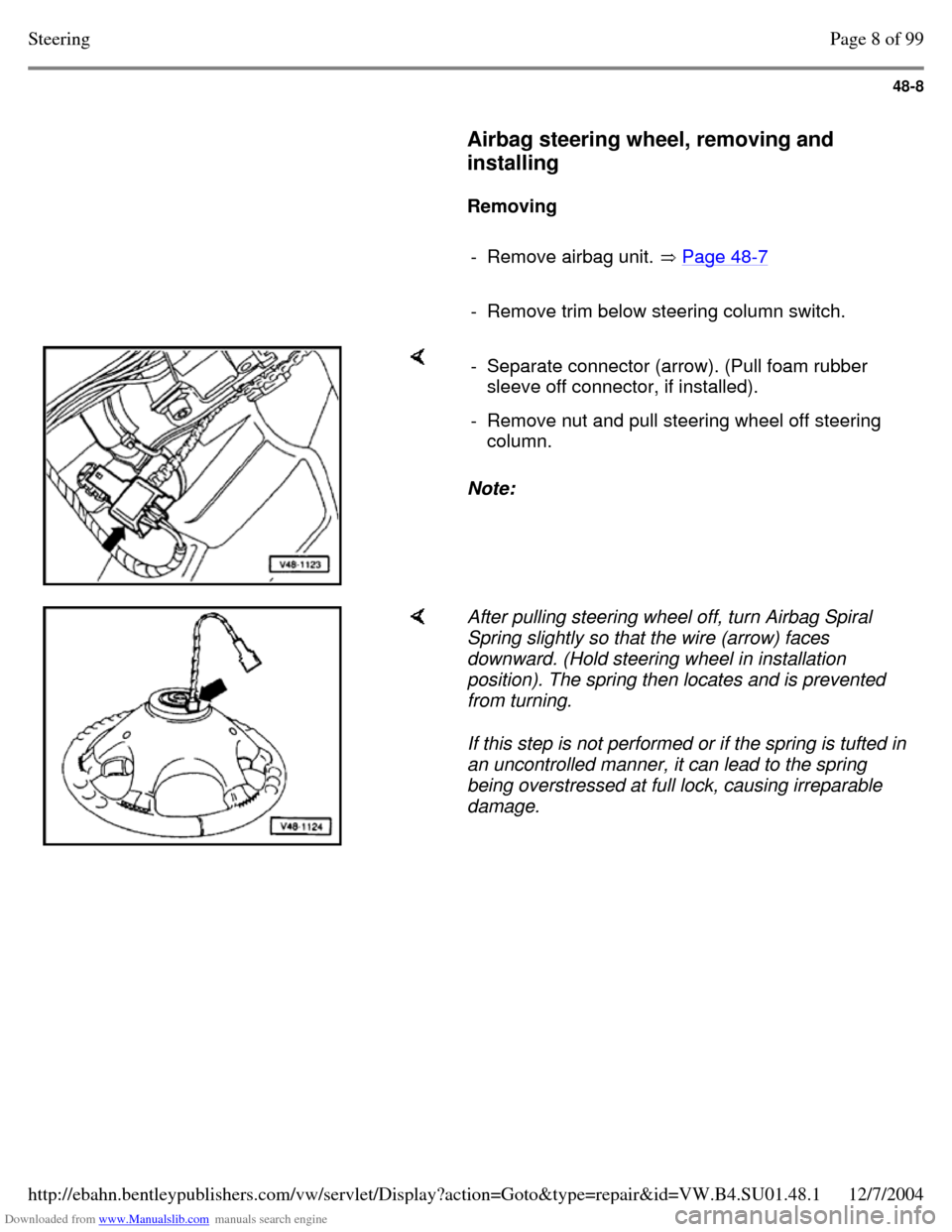
- Remove trim below steering column switch. Note: - Separate connector (arrow). (Pull foam rubber
sleeve off connector, if installed).
- Remove nut and pull steering wheel off steering
column. After pulling steering wheel off, turn Airbag Spiral
Spring slightly so that the wire (arrow) faces
downward. (Hold steering wheel in installation
position). The spring then locates and is prevented
from turning.
If this step is not performed or if the spring is tufted in
an uncontrolled manner, it can lead to the spring
being overstressed at full lock, causing irreparable
damage. Page 8 of 99Steering12/7/2004http://ebahn.bentleypublishers.com/vw/servlet/Display?action=Goto&type=repair&id=VW.B4.SU01.48.1
Page 282 of 369
Downloaded from www.Manualslib.com manuals search engine 48-12
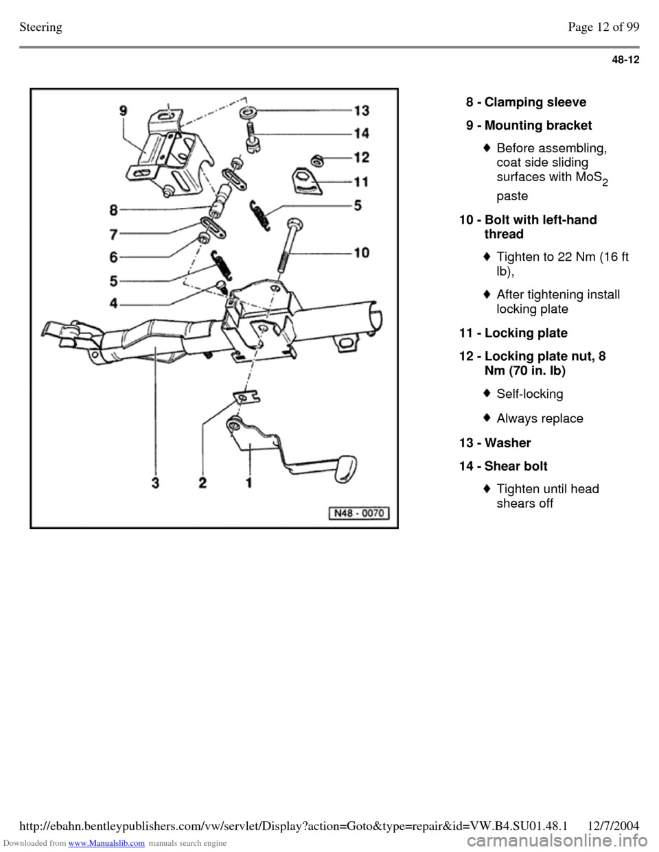
8 - Clamping sleeve
9 - Mounting bracket Before assembling,
coat side sliding
surfaces with MoS
2
paste
10 - Bolt with left-hand
thread Tighten to 22 Nm (16 ft lb), After tightening install
locking plate
11 - Locking plate
12 - Locking plate nut, 8
Nm (70 in. Ib) Self-locking Always replace 13 - Washer
14 - Shear bolt Tighten until head
shears off Page 12 of 99Steering12/7/2004http://ebahn.bentleypublishers.com/vw/servlet/Display?action=Goto&type=repair&id=VW.B4.SU01.48.1
Page 289 of 369
Downloaded from www.Manualslib.com manuals search engine 48-19
Assembly overview: power assisted
steering box (TRW)
Determine cause of any malfunctions using
pressure and leak testing, Page 48-13 .
Note:
Always replace self-locking nuts and bolts. Welding and straightening work on steering
components is not permitted.
To grease the rack only use steering gear
grease, Part No. AOF 063 000 04.
Type of oil: Hydraulic oil G 002 000 Oil system capacity: 0.7 - 0.9 ltr. (0.74 - 0.95
qt)
Supply and pressure line routing from Page 48-85 . Page 19 of 99Steering12/7/2004http://ebahn.bentleypublishers.com/vw/servlet/Display?action=Goto&type=repair&id=VW.B4.SU01.48.1
Page 290 of 369
Downloaded from www.Manualslib.com manuals search engine 48-20
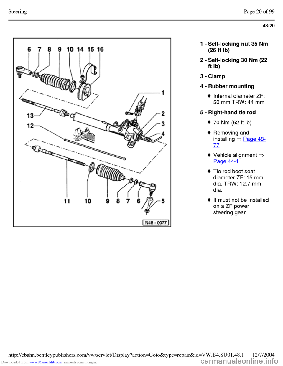
1 - Self-locking nut 35 Nm
(26 ft lb)
2 - Self-locking 30 Nm (22
ft lb)
3 - Clamp
4 - Rubber mounting Internal diameter ZF:
50 mm TRW: 44 mm
5 - Right-hand tie rod 70 Nm (52 ft lb) Removing and
installing Page 48-77 Vehicle alignment
Page 44-1 Tie rod boot seat
diameter ZF: 15 mm
dia. TRW: 12.7 mm
dia. It must not be installed
on a ZF power
steering gear Page 20 of 99Steering12/7/2004http://ebahn.bentleypublishers.com/vw/servlet/Display?action=Goto&type=repair&id=VW.B4.SU01.48.1
Page 294 of 369
Downloaded from www.Manualslib.com manuals search engine 48-24
Power steering gear, adjusting (TRW)
Note:
Two Mechanics are required when adjusting.
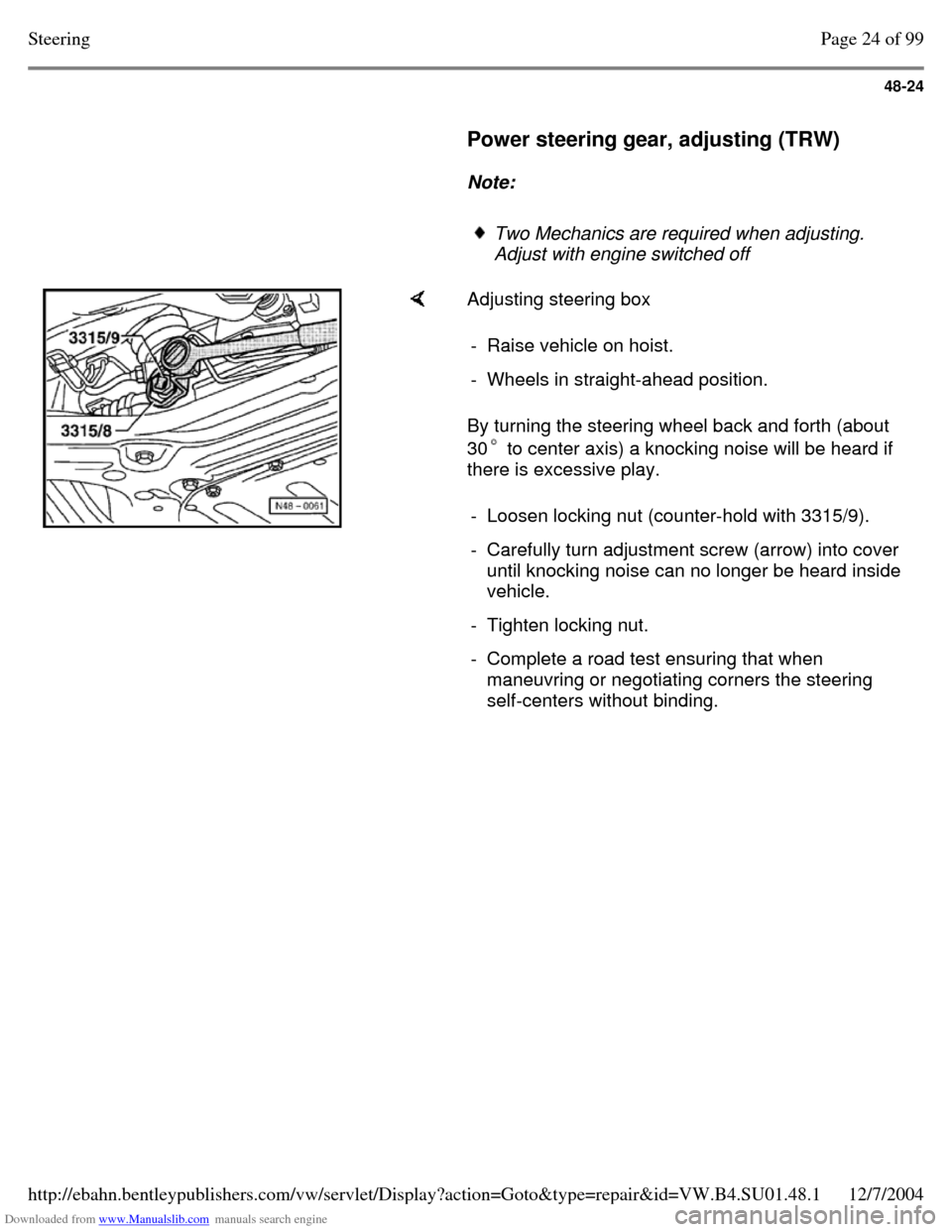
Adjust with engine switched off Adjusting steering box
By turning the steering wheel back and forth (about
30 to center axis) a knocking noise will be heard if
there is excessive play. - Raise vehicle on hoist. - Wheels in straight-ahead position. - Loosen locking nut (counter-hold with 3315/9). - Carefully turn adjustment screw (arrow) into cover
until knocking noise can no longer be heard inside
vehicle.
- Tighten locking nut. - Complete a road test ensuring that when
maneuvring or negotiating corners the steering
self-centers without binding. Page 24 of 99Steering12/7/2004http://ebahn.bentleypublishers.com/vw/servlet/Display?action=Goto&type=repair&id=VW.B4.SU01.48.1