lock VOLKSWAGEN PASSAT 1995 B3, B4 / 3.G Service Owner's Manual
[x] Cancel search | Manufacturer: VOLKSWAGEN, Model Year: 1995, Model line: PASSAT, Model: VOLKSWAGEN PASSAT 1995 B3, B4 / 3.GPages: 369, PDF Size: 12.33 MB
Page 60 of 369
Downloaded from www.Manualslib.com manuals search engine 40-46
Drive shaft, repairing
Drive shafts on vehicles with Plus suspension
have shorter and finer splines on the outer joint.
The wheel bearing is secured by a 12-point nut.
The splines of the outer joint and the hub on Plus
suspensions are secured with locking fluid D 185
400 A2.
Drive shaft, removing and installing
Vehicles with Base suspension Page 40-14 Vehicles with Plus suspension Page 40-43
Note:
Grease quantity:
- - Outer constant velocity joint 100 g of G-6.3
grease
- - Inner constant velocity joint 110 g of G-6.3
grease
Greasing outer joint: press half of the grease
into the joint, and the other half evenly into the
boot.
Greasing inner joint: press half of the grease
into the inner joint from both sides, the other
half evenly into the boot.
When replacing the boot grease joint as
required. Page 46 of 82Front Wheel Suspension, Shafts and Axle12/7/2004http://ebahn.bentleypublishers.com/vw/servlet/Display?action=Goto&type=repair&id=VW.B4.SU01.40.1
Page 86 of 369
Downloaded from www.Manualslib.com manuals search engine 40-72
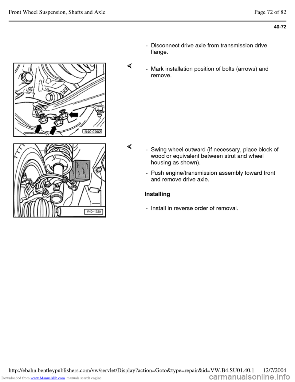
- Disconnect drive axle from transmission drive
flange. - Mark installation position of bolts (arrows) and
remove. Installing - Swing wheel outward (if necessary, place block of
wood or equivalent between strut and wheel
housing as shown).
- Push engine/transmission assembly toward front
and remove drive axle.
- Install in reverse order of removal. Page 72 of 82Front Wheel Suspension, Shafts and Axle12/7/2004http://ebahn.bentleypublishers.com/vw/servlet/Display?action=Goto&type=repair&id=VW.B4.SU01.40.1
Page 97 of 369
Downloaded from www.Manualslib.com manuals search engine 42-1
Rear Wheel
Suspension, Shafts
and Axle
Rear axle, servicing
(vehicles with front wheel
drive)
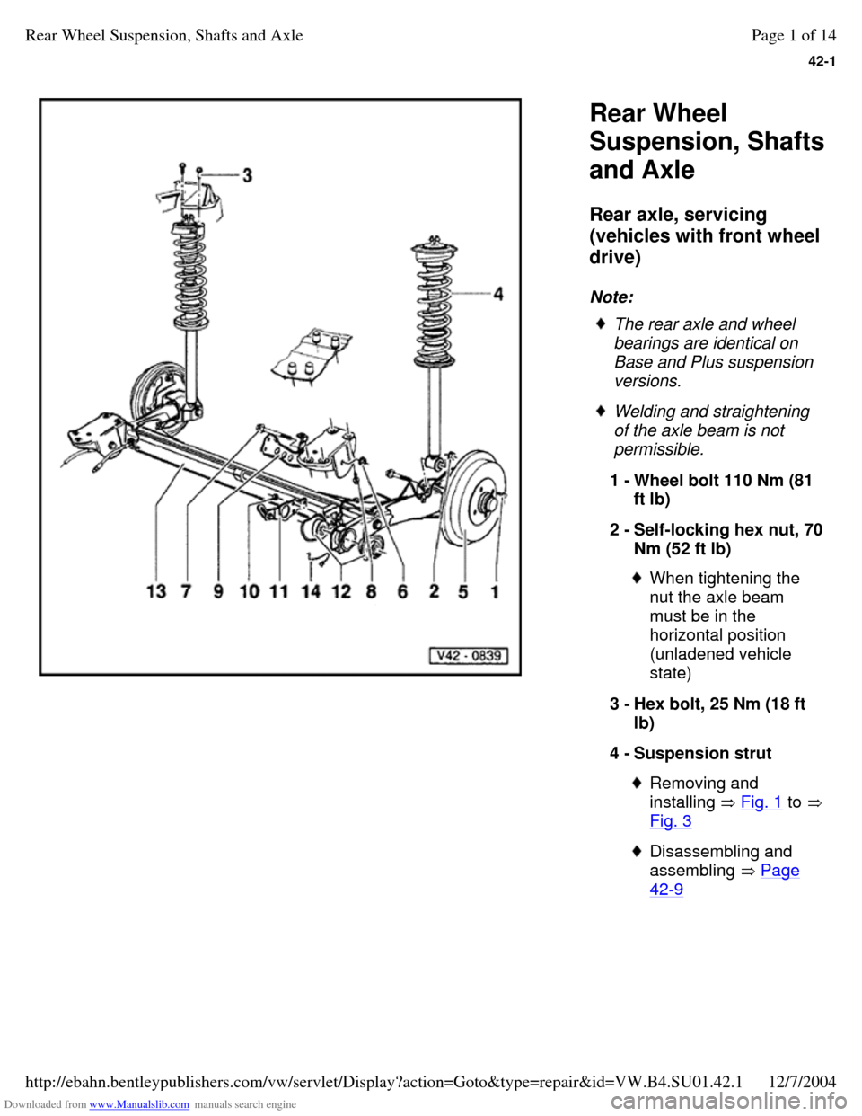
Note: The rear axle and wheel
bearings are identical on
Base and Plus suspension
versions. Welding and straightening
of the axle beam is not
permissible.
1 - Wheel bolt 110 Nm (81
ft lb)
2 - Self-locking hex nut, 70 Nm (52 ft lb) When tightening the
nut the axle beam
must be in the
horizontal position
(unladened vehicle
state)
3 - Hex bolt, 25 Nm (18 ft
lb)
4 - Suspension strut Removing and
installing Fig. 1 to Fig. 3 Disassembling and
assembling Page 42-9 Page 1 of 14Rear Wheel Suspension, Shafts and Axle12/7/2004http://ebahn.bentleypublishers.com/vw/servlet/Display?action=Goto&type=repair&id=VW.B4.SU01.42.1
Page 98 of 369
Downloaded from www.Manualslib.com manuals search engine 42-2
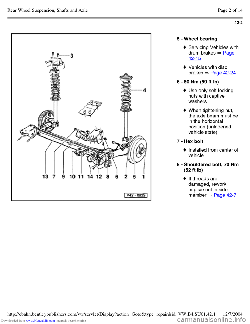
5 - Wheel bearing Servicing Vehicles with drum brakes Page 42-15 Vehicles with disc
brakes Page 42-24 6 - 80 Nm (59 ft lb) Use only self-locking
nuts with captive
washers When tightening nut, the axle beam must be in the horizontal
position (unladened
vehicle state)
7 - Hex bolt Installed from center of vehicle
8 - Shouldered bolt, 70 Nm (52 ft lb) If threads are
damaged, rework
captive nut in side
member Page 42-7 Page 2 of 14Rear Wheel Suspension, Shafts and Axle12/7/2004http://ebahn.bentleypublishers.com/vw/servlet/Display?action=Goto&type=repair&id=VW.B4.SU01.42.1
Page 105 of 369
Downloaded from www.Manualslib.com manuals search engine 42-9
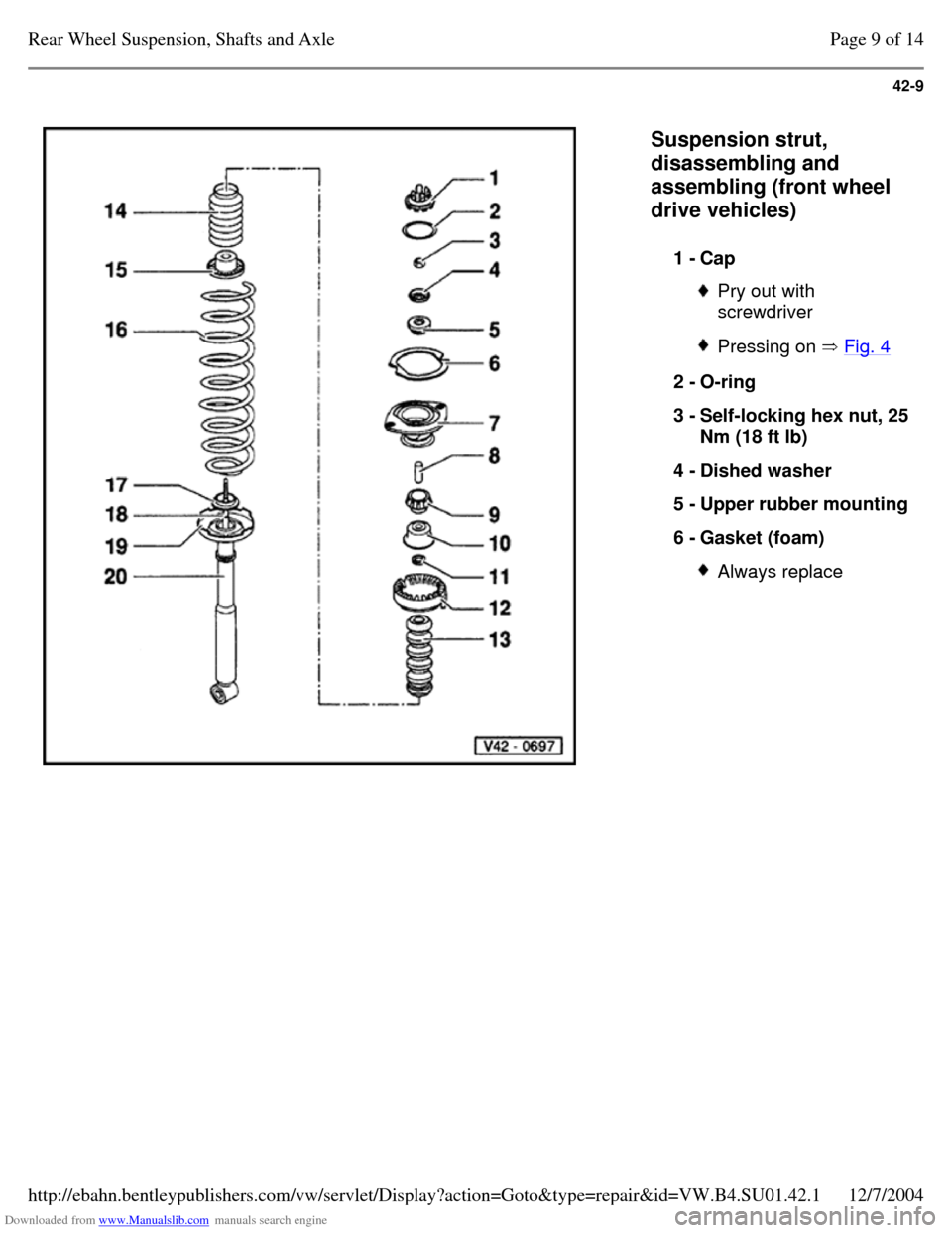
Suspension strut,
disassembling and
assembling (front wheel
drive vehicles)
1 - Cap Pry out with
screwdriver Pressing on Fig. 4 2 - O-ring
3 - Self-locking hex nut, 25 Nm (18 ft lb)
4 - Dished washer
5 - Upper rubber mounting 6 - Gasket (foam) Always replace Page 9 of 14Rear Wheel Suspension, Shafts and Axle12/7/2004http://ebahn.bentleypublishers.com/vw/servlet/Display?action=Goto&type=repair&id=VW.B4.SU01.42.1
Page 112 of 369
Downloaded from www.Manualslib.com manuals search engine 42-16
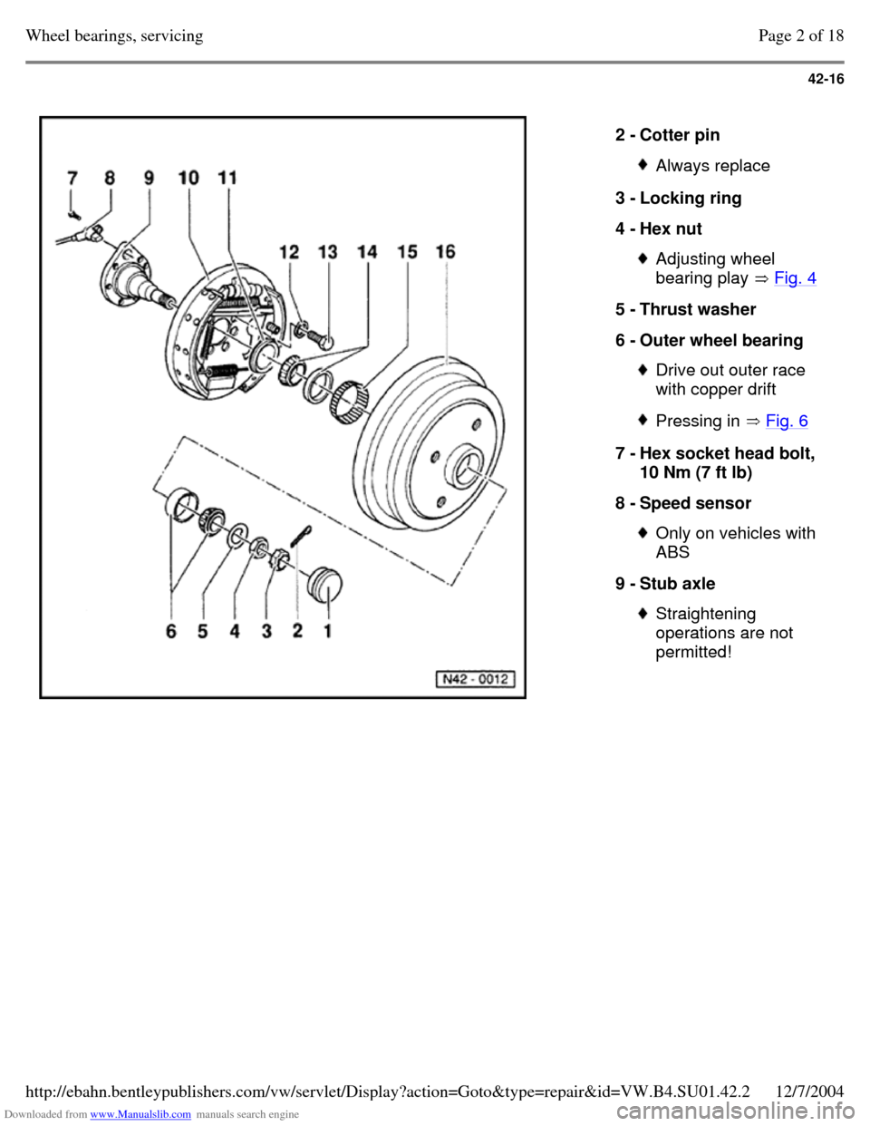
2 - Cotter pin Always replace 3 - Locking ring
4 - Hex nut Adjusting wheel
bearing play Fig. 4 5 - Thrust washer
6 - Outer wheel bearing Drive out outer race
with copper drift Pressing in Fig. 6 7 - Hex socket head bolt,
10 Nm (7 ft lb)
8 - Speed sensor Only on vehicles with
ABS
9 - Stub axle Straightening
operations are not
permitted! Page 2 of 18Wheel bearings, servicing12/7/2004http://ebahn.bentleypublishers.com/vw/servlet/Display?action=Goto&type=repair&id=VW.B4.SU01.42.2
Page 116 of 369
Downloaded from www.Manualslib.com manuals search engine 42-20
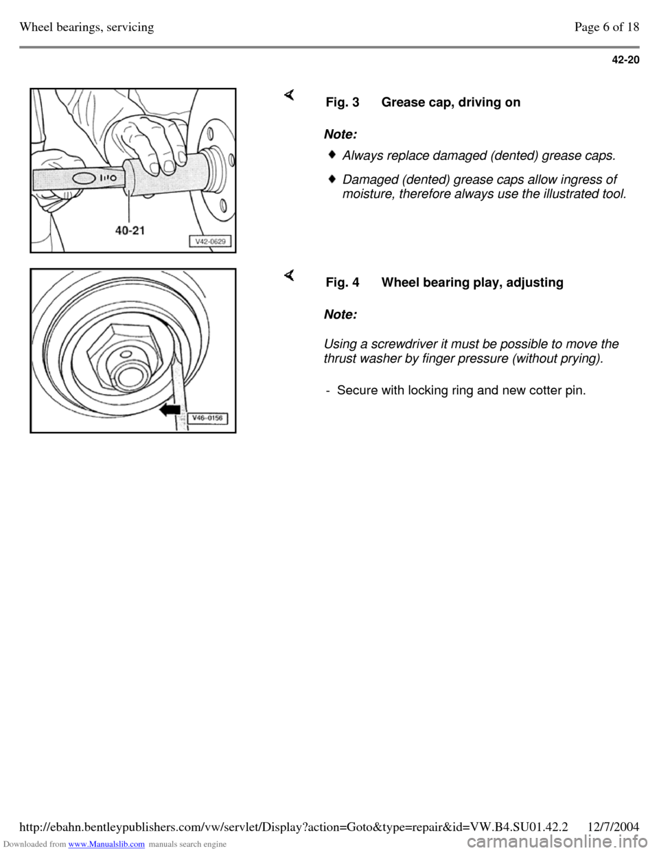
Note: Fig. 3 Grease cap, driving on Always replace damaged (dented) grease caps. Damaged (dented) grease caps allow ingress of
moisture, therefore always use the illustrated tool. Note:
Using a screwdriver it must be possible to move the
thrust washer by finger pressure (without prying). Fig. 4 Wheel bearing play, adjusting - Secure with locking ring and new cotter pin. Page 6 of 18Wheel bearings, servicing12/7/2004http://ebahn.bentleypublishers.com/vw/servlet/Display?action=Goto&type=repair&id=VW.B4.SU01.42.2
Page 121 of 369
Downloaded from www.Manualslib.com manuals search engine 42-25
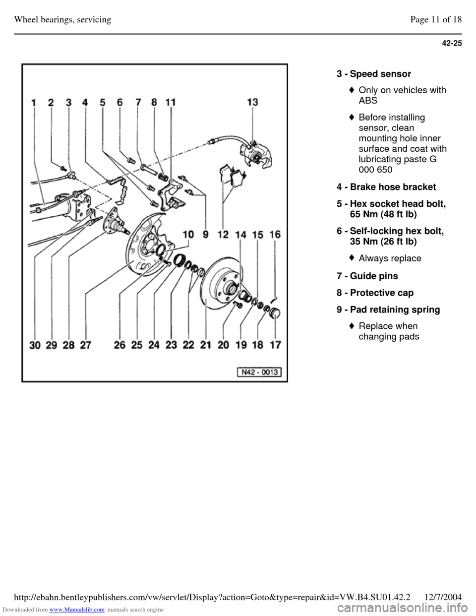
3 - Speed sensor Only on vehicles with
ABS Before installing
sensor, clean
mounting hole inner
surface and coat with
lubricating paste G
000 650
4 - Brake hose bracket
5 - Hex socket head bolt,
65 Nm (48 ft lb)
6 - Self-locking hex bolt,
35 Nm (26 ft lb) Always replace 7 - Guide pins
8 - Protective cap
9 - Pad retaining spring Replace when
changing pads Page 11 of 18Wheel bearings, servicing12/7/2004http://ebahn.bentleypublishers.com/vw/servlet/Display?action=Goto&type=repair&id=VW.B4.SU01.42.2
Page 123 of 369
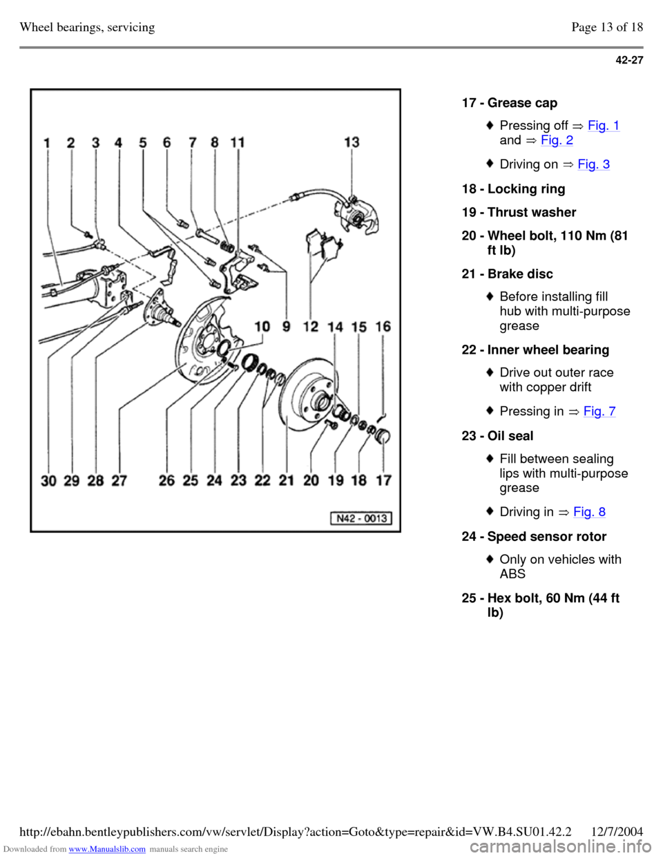
Downloaded from www.Manualslib.com manuals search engine 42-27
17 - Grease cap Pressing off Fig. 1
and Fig. 2 Driving on Fig. 3 18 - Locking ring
19 - Thrust washer
20 - Wheel bolt, 110 Nm (81
ft lb)
21 - Brake disc Before installing fill
hub with multi-purpose grease
22 - Inner wheel bearing Drive out outer race
with copper drift Pressing in Fig. 7 23 - Oil seal Fill between sealing
lips with multi-purpose
grease Driving in Fig. 8 24 - Speed sensor rotor Only on vehicles with
ABS
25 - Hex bolt, 60 Nm (44 ft
lb) Page 13 of 18Wheel bearings, servicing12/7/2004http://ebahn.bentleypublishers.com/vw/servlet/Display?action=Goto&type=repair&id=VW.B4.SU01.42.2
Page 126 of 369

Downloaded from www.Manualslib.com manuals search engine 42-30
Note: Fig. 3 Grease cap, driving on Always replace damaged (dented) grease caps. Damaged (dented) grease caps allow ingress of
moisture, therefore always use the illustrated tool. Note:
Using a screwdriver it must be possible to move the
thrust washer by finger pressure (without prying). Fig. 4 Wheel bearing play, adjusting - Secure with locking ring and new cotter pin. Page 16 of 18Wheel bearings, servicing12/7/2004http://ebahn.bentleypublishers.com/vw/servlet/Display?action=Goto&type=repair&id=VW.B4.SU01.42.2