brake sensor VOLKSWAGEN PASSAT 1996 B3, B4 / 3.G Service Workshop Manual
[x] Cancel search | Manufacturer: VOLKSWAGEN, Model Year: 1996, Model line: PASSAT, Model: VOLKSWAGEN PASSAT 1996 B3, B4 / 3.GPages: 369, PDF Size: 12.33 MB
Page 4 of 369

Downloaded from www.Manualslib.com manuals search engine Rear axle, servicing (four wheel drive vehicles)
Rear drive shafts, servicing
Reworking cap nut in side member (four wheel drive vehicles)
Suspension strut, disassembling and assembling (four wheel drive
vehicles)
Wheel bearings, servicing - disc brakes (four wheel drive vehicles)
44 - Wheels, Tires, Wheel alignment
Vehicle alignment
Test requirements:
Vehicle alignment specifications (front wheel drive vehicles)
Vehicle alignment specifications (four wheel drive vehicles)
Front wheel camber, adjusting
Calculating the direction of travel:
45 - Anti-lock brake system
Anti-locking Brake System (ABS) and Anti-locking Brake System with
Electronic Differential Lock (ABS/EDL) Teves 04
Notes for repair work on ABS, ABS/EDL
Control module, removing and installing
Wheel speed sensor and rotor for speed sensor, removing and installing
Anti-lock Brake System (ABS) and ABS with Electronic Differential Lock
(ABS/EDL), Teves 20 GI
Safety precautions
ABS, ABS/EDL hydraulic unit, vacuum brake booster and brake master
cylinder (Teves 20 GI), servicing
ABS hydraulic unit and ABS control module (Teves 20 GI), removing and
installing
Brake hydraulic system, bleeding and filling
Assembly overview - hydraulic unit, brake servo/brake master cylinder
Hydraulic unit, removing and installing
Brake Pedal Position Sensor, removing and installing
46 - Brakes - Mechanical components
Front brakes, servicing (Girling caliper)
Brake pads, removing and installing
Page 51 of 369
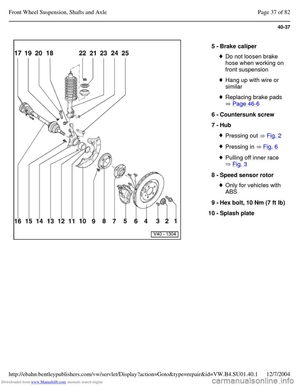
Downloaded from www.Manualslib.com manuals search engine 40-37
5 - Brake caliper Do not loosen brake
hose when working on
front suspension Hang up with wire or
similar Replacing brake pads
Page 46-6 6 - Countersunk screw
7 - Hub Pressing out Fig. 2 Pressing in Fig. 6 Pulling off inner race
Fig. 3 8 - Speed sensor rotor Only for vehicles with
ABS
9 - Hex bolt, 10 Nm (7 ft lb) 10 - Splash plate Page 37 of 82Front Wheel Suspension, Shafts and Axle12/7/2004http://ebahn.bentleypublishers.com/vw/servlet/Display?action=Goto&type=repair&id=VW.B4.SU01.40.1
Page 113 of 369
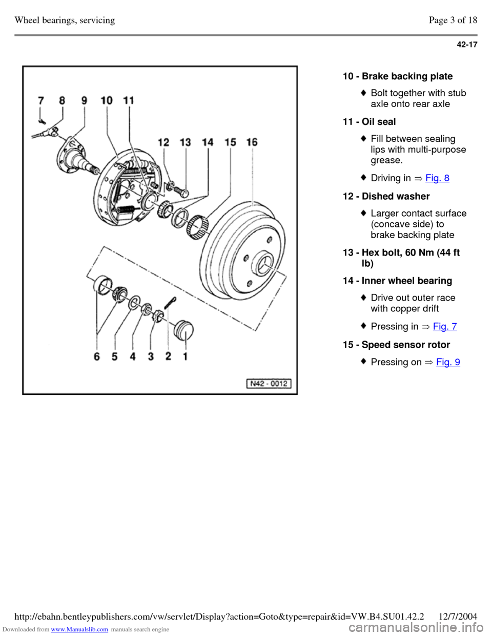
Downloaded from www.Manualslib.com manuals search engine 42-17
10 - Brake backing plate Bolt together with stub
axle onto rear axle
11 - Oil seal Fill between sealing
lips with multi-purpose
grease. Driving in Fig. 8 12 - Dished washer Larger contact surface
(concave side) to
brake backing plate
13 - Hex bolt, 60 Nm (44 ft
lb)
14 - Inner wheel bearing Drive out outer race
with copper drift Pressing in Fig. 7 15 - Speed sensor rotor Pressing on Fig. 9 Page 3 of 18Wheel bearings, servicing12/7/2004http://ebahn.bentleypublishers.com/vw/servlet/Display?action=Goto&type=repair&id=VW.B4.SU01.42.2
Page 121 of 369
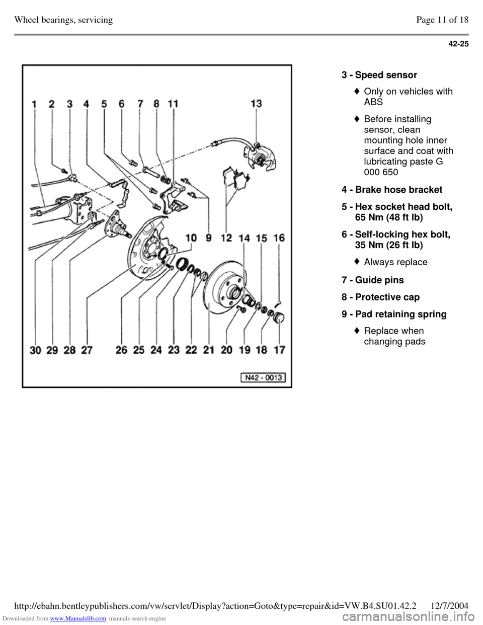
Downloaded from www.Manualslib.com manuals search engine 42-25
3 - Speed sensor Only on vehicles with
ABS Before installing
sensor, clean
mounting hole inner
surface and coat with
lubricating paste G
000 650
4 - Brake hose bracket
5 - Hex socket head bolt,
65 Nm (48 ft lb)
6 - Self-locking hex bolt,
35 Nm (26 ft lb) Always replace 7 - Guide pins
8 - Protective cap
9 - Pad retaining spring Replace when
changing pads Page 11 of 18Wheel bearings, servicing12/7/2004http://ebahn.bentleypublishers.com/vw/servlet/Display?action=Goto&type=repair&id=VW.B4.SU01.42.2
Page 123 of 369
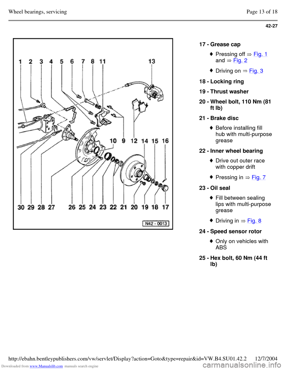
Downloaded from www.Manualslib.com manuals search engine 42-27
17 - Grease cap Pressing off Fig. 1
and Fig. 2 Driving on Fig. 3 18 - Locking ring
19 - Thrust washer
20 - Wheel bolt, 110 Nm (81
ft lb)
21 - Brake disc Before installing fill
hub with multi-purpose grease
22 - Inner wheel bearing Drive out outer race
with copper drift Pressing in Fig. 7 23 - Oil seal Fill between sealing
lips with multi-purpose
grease Driving in Fig. 8 24 - Speed sensor rotor Only on vehicles with
ABS
25 - Hex bolt, 60 Nm (44 ft
lb) Page 13 of 18Wheel bearings, servicing12/7/2004http://ebahn.bentleypublishers.com/vw/servlet/Display?action=Goto&type=repair&id=VW.B4.SU01.42.2
Page 158 of 369
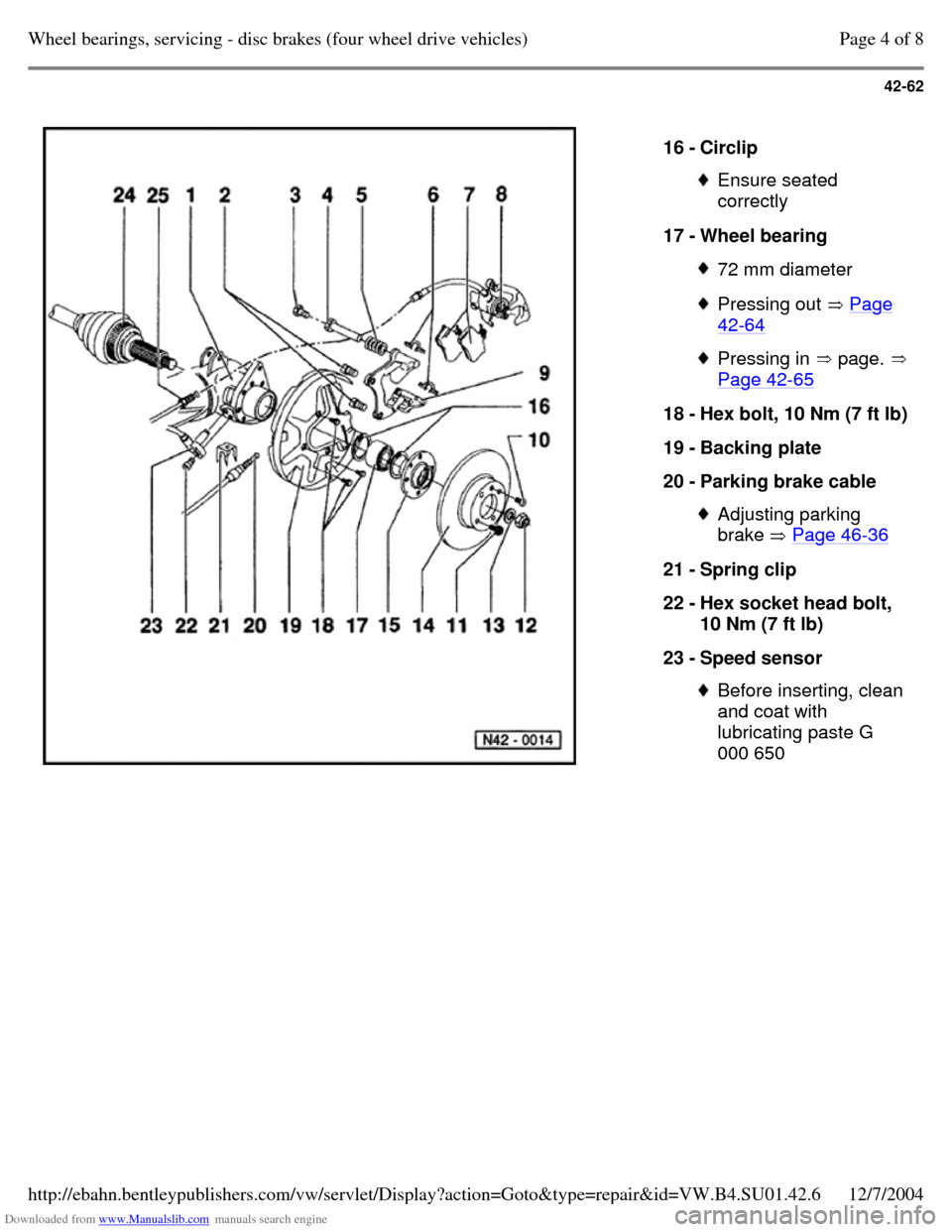
Downloaded from www.Manualslib.com manuals search engine 42-62
16 - Circlip Ensure seated
correctly
17 - Wheel bearing 72 mm diameter Pressing out Page 42-64 Pressing in page. Page 42-65 18 - Hex bolt, 10 Nm (7 ft lb) 19 - Backing plate
20 - Parking brake cable Adjusting parking
brake Page 46-36 21 - Spring clip
22 - Hex socket head bolt,
10 Nm (7 ft lb)
23 - Speed sensor Before inserting, clean
and coat with
lubricating paste G
000 650 Page 4 of 8Wheel bearings, servicing - disc brakes (four wheel drive vehicles)12/7/2004http://ebahn.bentleypublishers.com/vw/servlet/Display?action=Goto&type=repair&id=VW.B4.SU01.42.6
Page 159 of 369
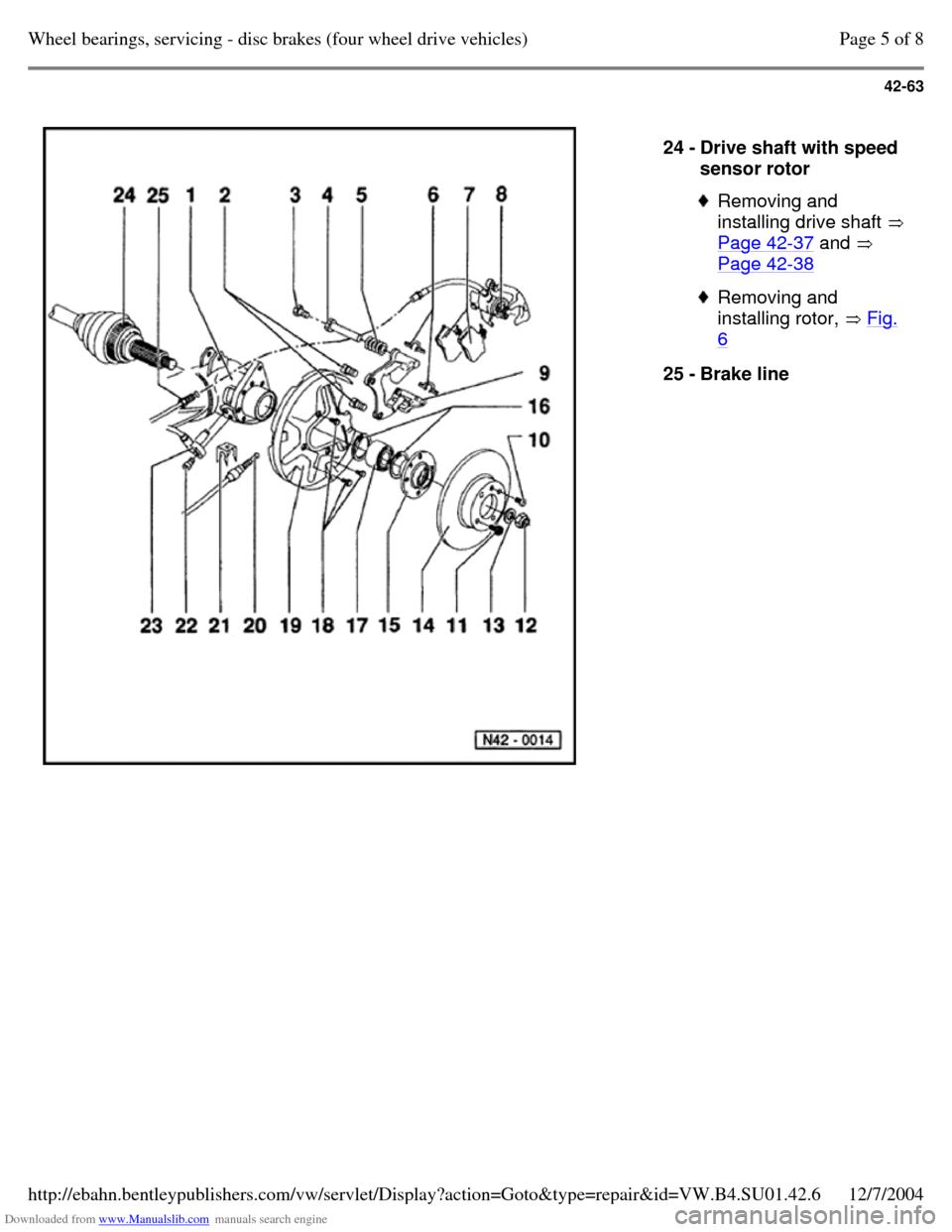
Downloaded from www.Manualslib.com manuals search engine 42-63
24 - Drive shaft with speed
sensor rotor Removing and
installing drive shaft
Page 42-37 and
Page 42-38 Removing and
installing rotor, Fig. 6 25 - Brake line Page 5 of 8Wheel bearings, servicing - disc brakes (four wheel drive vehicles)12/7/2004http://ebahn.bentleypublishers.com/vw/servlet/Display?action=Goto&type=repair&id=VW.B4.SU01.42.6
Page 162 of 369
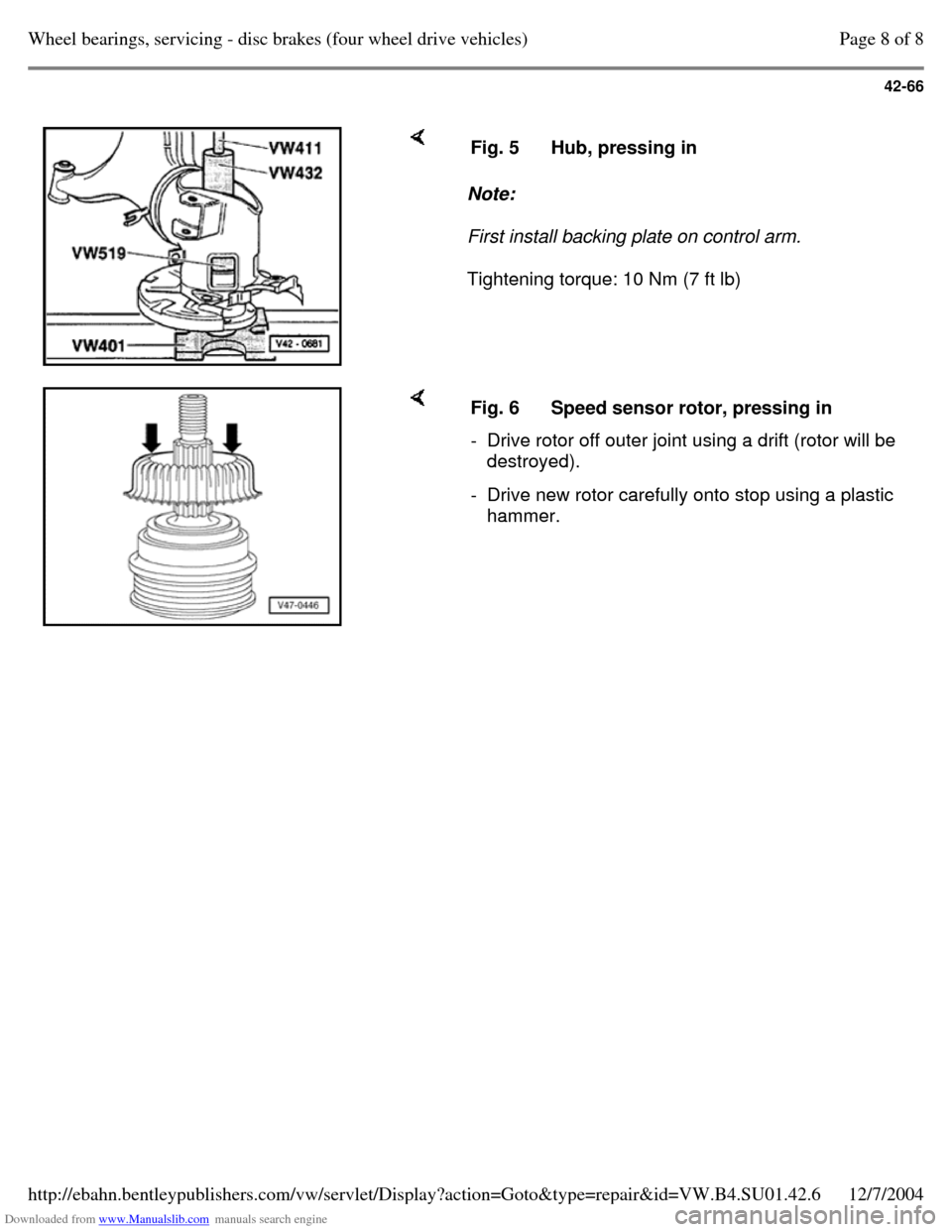
Downloaded from www.Manualslib.com manuals search engine 42-66
Note:
First install backing plate on control arm.
Tightening torque: 10 Nm (7 ft lb) Fig. 5 Hub, pressing in Fig. 6 Speed sensor rotor, pressing in - Drive rotor off outer joint using a drift (rotor will be
destroyed).
- Drive new rotor carefully onto stop using a plastic
hammer. Page 8 of 8Wheel bearings, servicing - disc brakes (four wheel drive vehicles)12/7/2004http://ebahn.bentleypublishers.com/vw/servlet/Display?action=Goto&type=repair&id=VW.B4.SU01.42.6
Page 174 of 369
Downloaded from www.Manualslib.com manuals search engine 45-5
Wheel speed sensor and rotor for speed
sensor, removing and installing
Speed sensor
When installing speed sensor ensure wiring is
not twisted.
Before installing speed sensor, clean mounting
hole and coat with lubricating paste, G 000 650.
Rotors
Before installing check that rotor is clean and
undamaged.
Front axle
Vehicles with base suspension Page 40-14 . Vehicles with plus suspension Page 40-23 .
Rear axle
Vehicles with rear drum brakes Page 42-15 . Vehicles with rear disc brakes (front and four
wheel drive Page 42-24 . Page 5 of 5Anti-locking Brake System (ABS) and Anti-locking Brake System with Electronic Differential Lock (A...12/7/2004http://ebahn.bentleypublishers.com/vw/servlet/Display?action=Goto&type=repair&id=VW.B4.SU01.45.1
Page 187 of 369
Downloaded from www.Manualslib.com manuals search engine 45-18
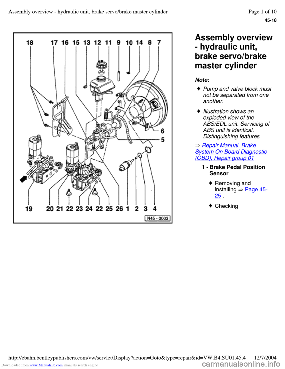
Assembly overview
- hydraulic unit,
brake servo/brake
master cylinder
Note:
Repair Manual, Brake System On Board Diagnostic (OBD), Repair group 01 Pump and valve block must
not be separated from one
another. Illustration shows an
exploded view of the
ABS/EDL unit. Servicing of
ABS unit is identical.
Distinguishing features 1 - Brake Pedal Position
Sensor Removing and
installing Page 45-25 . Checking Page 1 of 10Assembly overview - hydraulic unit, brake servo/brake master cylinder12/7/2004http://ebahn.bentleypublishers.com/vw/servlet/Display?action=Goto&type=repair&id=VW.B4.SU01.45.4